Sign In
Upload
Manuals
Brands
Valtra Manuals
Tractor
VALMET 6300
Valtra VALMET 6300 Tractor Manuals
Manuals and User Guides for Valtra VALMET 6300 Tractor. We have
3
Valtra VALMET 6300 Tractor manuals available for free PDF download: Workshop Manual, Service Manual
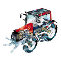
Valtra VALMET 6300 Workshop Manual (1362 pages)
Brand:
Valtra
| Category:
Tractor
| Size: 41.74 MB
Table of Contents
Electrical System
2
General
4
Layout
10
Division into Groups
10
Division into Components or Sub ---Groups
10
Code Designation
11
Page Numbers
11
Date
11
General Instructions for Repairs
14
Outer Oil Seals
14
Sealing Compound and Glue
14
Tightening Torques and Setting Values
14
Handling of Heavy Components
15
Cleanliness
15
Assembly
15
Lubrication
15
Bushes and Press Fits
16
Cables and Wires
16
Locking Devices
16
Fitting Bolts in Blind Holes
16
Tightening Torques, Metric Standard Thread (ISO)
17
Conversion Table for Common Units
18
General Instructions Concerning Oil Checks and Oil Filling
20
Greasing Lubricating Points Fitted with Grease Nipples
20
Lubrication and Maintenance Schedule
20
Maintenance Schedule
21
Daily/Every 10 Hours
21
Weekly/Every 50 Hours
21
Every 250 Hours
21
Every 500 Hours
22
Every 1000 Hours/Yearly
22
Every 2000 Hours/Every Other Year
22
Every 4000 Hours
22
Recommended Fuel and Lubricants
23
Oil Quality and Capacity in Fluid Couplings
23
Engine
24
Table of Contents
26
Specifications
28
Valves, Rockers and Tappets
30
Connecting Rod
32
Special Tools
37
Engine, Description
39
Cylinder Block
39
Flywheel Housing
39
Crank Mechanism
40
Cylinder Head
40
Valve Mechanism
40
Timing Gears
41
Lubricating System
42
Induction and Exhaust System
43
Repair Instructions
48
Checking Cylinder Block
48
Removing Cylinder Liner
48
Cylinder Block and Flywheel Housing (Op no 211)
48
Measuring Cylinder Liner Wear
48
Changing Camshaft Bushing
48
Oversize Bushings for Camshaft
49
Fitting Pipe for Oil Dipstick
51
Fitting Cylinder Liners
51
Fitting Flywheel Housing
53
Changing Crankshaft Rear Oil Seal
53
Changing Flywheel Starter Gear
54
Fitting Flywheel
54
Removing Cylinder Head
56
Removing Valves
56
Checking Cylinder Head
56
Cylinder Head and Valve Mechanism (Op no 212)
56
Changing Valve Guides
57
Machining Valve Seat
57
Changing Valve Seat Inserts
58
Grinding Valves
58
Fitting Valves
58
Fitting Cylinder Head
59
Reconditioning Rocker Arm Mechanism
60
Changing Camshaft/Camshaft Gear
60
Valve Mechanism
60
Adjusting Valves
61
Removing Crankshaft
62
Changing Crankshaft Gears
62
Crank Mechanism (Op. no 213)
62
Fitting Crankshaft
63
Changing Crankshaft Ring Gear (420
63
Connecting Rods and Pistons
64
Removing Piston Together with Connecting Rod
64
Changing Connecting Rod Bearings
64
Connecting Rods, Weight Classes
65
Changing Piston Rings
66
Checking Piston
67
Fitting Piston Together with Connecting Rod
67
Balancer Unit, 420
68
Removing and Dismantling Balancer Unit
68
Reconditioning Balancer Unit
68
Fitting Balancer Unit
69
Removing Timing Gear Casing
70
Reconditioning Idler Gear
70
Fitting Timing Gear Casing
71
Reconditioning of Oil Relief Valve for Lubricating Oil Pressure
74
Removing and Dismantling Lubricating Oil Pump
74
Assembling and Fitting Lubricating Oil Pump
75
Fitting Oil Sump Gasket
75
Lubricating Oil Quality Requirements
76
Cooling Nozzles for Pistons
77
Latest Lubricating Oil Pressure Relief Valve
77
Inlet and Exhaust System, Turbocharger (Op. No. 216)
80
Checking Inlet and Exhaust System
80
Checking Turbocharger
80
Reconditioning Turbocharger
82
Cleaning Parts of the Turbocharger
83
Checking Parts of the Turbocharger
83
Assembling the Turbocharger
83
Bearing Housing
83
Fitting Turbocharger
84
Adjusting by -Pass Turbo (S1BG)
84
Intercooler on 6800 Tractor
85
Exhaust Pipe on 6800 Tractor
86
Crankshaft Seals
88
Pistons and Connecting Rods
88
Lubricating Oil Pump
88
Working Orders (Op. No. 219)
88
Camshaft
89
Specifications
91
Special Tools
92
Fuel System, Description
93
Fuel Filter
93
Fuel Tank
93
Injectors
93
Fuel Injection Pump
94
Two-Hole Pump Element (Maximum Feed)
95
Delivery Valve
95
Checking Electric Stop Solenoid
96
Fuel Injection Pump (Bosch P-- Pump) on 8950 Tractor
96
Governor
98
Fuel Injection Pump Type Plate
98
Table of the Fuel Metering 6000-6800
99
Specifications with Stanadyne Distributor Pump
103
Stanadyne Distributor Pump
103
Fuel System with Distributor Pump
104
Maintenance
104
Construction
105
Possible Equipment on Stanadyne Distributor Pump
106
Electric Advancing of the Injection
107
Bleeding Fuel System
112
Bleeding Thermostart System
112
Measuring Fuel Feed Pressure
112
Repair Instructions
112
Checking Overflow Valve
113
Changing Fuel Feed Pump Valves
113
Checking Fuel Injection Timing
114
Adjusting Injection Timing
114
Removing Injection Pump
115
Fitting Injection Pump
115
Checking/Changing Delivery Valve
116
Adjusting Low Idling Speed
117
Removing Injectors
118
Inspecting Injectors
118
Opening Pressure
118
Chattering Sound Properties
118
Reconditioning Injectors
119
Tightness of Nozzle
119
Fitting Injector in Engine
120
Fitting Delivery Pipes
120
Adjusting Injection Timing on 6800, 8750 and 8950 Tractors
121
Manifold Pressure Compensator
122
Cold Start Solenoid
122
Boost Control
122
Removing Distributor Pump
123
Fitting Pump and Adjusting Injection Timing
123
Stanadyne Distributor Pump
123
Fuel Feed Pump
124
Bleeding Fuel System
124
Injectors
125
Adjusting Low Idling Speed
125
Delivery Pipes
125
Cooling System
128
Specifications
129
Special Tools
130
Freezing Point of Coolant
131
Expansion Tank
132
Emptying the System in Connection with Repairs
132
Viscous Fan
133
Temperature Sensor, Engine Coolant Temperature
134
Coolant Pump
135
Repair Instructions (Op no 231)
136
Thermostat
136
Reconditioning Coolant Pump (320
136
Reconditioning Coolant Pump (620
136
Coolant Pump on 8000, 8100, 8200 and 8400
137
Quality Requirements of Engine Coolant
138
Coolant Pump and Thermostat Housing
139
Electrical System
144
Tractor Electrical System
146
Safety Precautions for the Electrical System
146
Battery Checks and Maintenance
146
Fuses and Relays
147
Circuit Card, Fuse Box
147
Headlight Adjustment
148
Standard Trailer Socket
148
Electrical Equipment for Engine
149
Alternator Iskra AAK 5118 14 V 95 a
150
Alternator Bosch NC 14 V 70---120 a
150
Starter Motor Iskra AZJ3234 12 V 3,1 Kw
151
Starter Motor Iskra AZJ3247 12 V 3,6 Kw
151
Speed Radar
152
Radar Fastening Parts
153
Electric Connections
153
Position of Electric Components on Frame
154
Wiring Diagram
164
Differential Lock
268
Front Wheel Drive
268
Power Take -Off
269
Delta Powershift
269
Components of the Autocontrol II
270
Delta Power Shift Control
271
Circuit Card of Buzzer and Ind. Lights
273
Fault Tracing
273
Buzzer Test
273
Circuit Card Illumination
273
Differential Lock Control
274
Checking Function of the Differential Lock Control
275
4WD Control
276
Checking Function
276
PTO Control
277
Differences between AC II and AC
278
Delta Powershift Control System
278
Sound Signals
278
Control of Transmission
278
DPS Circuit Card
280
INPUT Signals
280
OUTPUT Signals
280
Fault Tracing of Input Signals
280
Control Stop
281
Function
281
Testing the Function
281
Differences in the Dashboard
282
Position of Connectors
283
Engine Speed Sensor B4
283
Power Control Unit
283
PTO Speed Sensor
283
Version Markings of Sigmapower
284
Sigma Power 2.0
284
Control Unit A13
286
Solenoid Valve Y13 and Boost Control
286
Sensors B4 and B5, Versions 1.0, 1.1 and 2.0
287
Fault Tracing, Adjustments and Repairs
293
Checking Function with the Aid of the ETB
293
Fault Tracing by Measuring Voltages
294
Incorrect Voltage Readings
295
Checking and Adjusting Sensors with Fluke123
296
Interpretation of Oscilloscope Waves and Specified Values
297
Buzzer Functions
305
DPS-Circuit Card A10
306
Wiring Diagram
314
Position Control Knob
320
Lift/Lower Switch
320
Lowering Speed Selector
320
Transport Height Selector
320
Position Sensor
321
Adjusting the Position Sensor
321
Draft Sensors
322
Short Circuit in Draft Sensor Line
322
Functional Checks
323
Distinguishing between Electrical and Hydraulic Malfunctions
323
Checking the Electrical Operations
323
Checking the Lift/Lower Switch
323
Checking the Indicator Lights on Switch Panel
324
Checking the Transport Height Selector
324
Checking the Lower Speed Selector
324
Checking the Draft Control Operation
324
Checking Switch Panel A2E
325
Removing the Switch Panel for Checking
325
Voltage Measurements
326
Checking Supply Voltage
326
Checking Lowering Speed Selector
326
Checking Transport Height Selector
326
Changing Switch Panel
327
Checking Switch Panel Indicator Lights
327
Measuring Internal Voltages of Position Sensor and Draft Sensors
328
Checking the Position Control Potentio-Meter
329
Checking Control Valve and Its Solenoid Valves
329
Special Instructions
331
Control Unit A1E of AC Power Lift
331
Forced Lowering
331
ACB / ACD Power Lift
332
Position Sensor, ACB and ACD
333
Measuring Position Sensor Supply and Signal Voltages
333
Function of Diagnostic Light and Fault Codes
334
Faul Codes of ACD Power Lift
334
Serious Faults
334
Medium Serious Faults
335
Minor Faults
335
Other Faults
335
Fault Codes of ACB Power Lift
336
Drive Balance Control (DBC)
338
Verifying the Function of the DBC
338
ACD: Transmission Speed Sensor
338
Clip Control (Option)
339
Calibrating Drive
339
Checking Switch Panel of ACD
340
Measuring Supply Voltage
340
Checking Lowering Speed Selector S7E
340
Checking Transport Height Selector S8E
340
Checking Dbc/Slip Control Selector S12E
341
Checking Lift/Lower Switch S10E
341
Checking Switch Panel of ACB
342
Changing Switch Panel, ACB/ACD
343
Checking Control Valve and Its Solenoid Valves (Not ACB)
344
Adjusting Position Sensor, ACB/ACD
344
Wiring Diagram, ACD
345
ACD: List of Components
346
Circuit Diagram, ACB
347
ACB: List of Components
348
ACD Power Lift
349
Checking Function of ACB and ACD Power Lifts
351
Agrodata Performance Monitor
354
Checking Display Operation
356
Trouble Shooting
356
Checking the Sensors and Signal from Lift/Lower Switch
357
Connecting the Leads from the Implement Sensor to the Plug Poles
357
Spare Part Numbers for Sensors and Plug
358
Further Information on Agrodata Operation
358
Agrodata-Instrument
360
Agrodata-Instrument, Sensors and Wiring
361
Zeroing the Travelling Distance
362
Time Setting
362
Gearbox Speed Sensor B6
363
PTO Speed Sensor B7
363
Calibrating the Instrument for Different Tyres
364
Gearbox Temperature Sensor B3
364
Code Numbers with Different Tyre Sizes and Transmission Types
365
Fieldmaster
368
Connectors
369
Fieldmaster Components on the Tractor
369
Fieldmaster Wiring Diagram
370
General Functions
371
Calibrating Gearbox Speed Sensor and Radar
371
Changing Display Language
371
Error Messages
372
Test Mode
373
Sprayer
373
Fertilizer
373
Drill
373
Checking Wire Connections between Rear Socket and Display Unit
374
Baler
374
Slurry Spreader
374
Connecting Sensor Wires to Plug
375
Lower Row Shows
378
Upper Row Shows
378
Zeroing Distance Travelled
378
Setting Time
378
Calibrating Agroline for Different Tyres
379
Fault Codes
381
Changing Speed and Distance Units
381
Sensors and Switches
382
Rear PTO Speed Sensor
382
Gearbox Oil Temperature
383
Engine Temperature Sensor
384
Engine Oil Pressure Sensor
384
Fuel Level Sensor
384
Sensor S12 for Engine Air Filter Warning Light
384
Gearbox Oil Pressure
385
Switch S44 for Blocked Pressure Filter
385
Gearbox Oil Temperatute Switch S16
385
Parking Brake Warning Light Switch
385
Direction Indicator Flashers
386
Indication Light for Glowing
386
Charging Light
386
Hour Recorder and Rev Counter
386
Components for AC-III System
392
Sensor for Outdoor Temperature
392
Sensor for Engine Coolant Temperature
392
Sensor for Front Wheel Steering Angle
392
Calibrating Mode for the Hidden Functions
393
Parameters
393
Harness Looms and Connectors
396
Central Processing Unit (ECS) Is Placed in the Lever
396
Rear Side of the ECS
396
Component List for Wiring Diagram
397
Trouble Shooting and Repairs
404
Checking and Fitting Sensors
404
Fitting Speed Sensors
404
Calibrating the Speed Sensors
404
Potentiometer on the Fuel Injection Pump
405
Sensor for Steering Angle
405
Manual Fault Tracing
406
Supply Voltages
406
Ecs
406
Functional Check
407
Quick-- Shift Gear
408
Calibrating the Quick-Shift Gear
408
Power Take - off
408
Slip Control
409
Cold Starting Device
409
Setting Slip Percent
409
Counter Functions
410
Calibrating Display
410
Zeroing the Counters
410
Starting and Stopping Counters
410
Computer-Aided Fault Tracing
412
Starting Fault Tracing
412
Fault Tracing Chart on PC Monitor
413
Fault Tracing, Front Wheel Drive Control
414
Fault Tracing, Quick -Shift Gear Control
415
Fault Tracing, Differential Lock Control
415
Fault Tracing, Power Take -Off Control
416
Fault Tracing, Slip Control
417
Fault Tracing, Speed Sensors
418
Checking Radar
418
Checking Speed Sensors for Front Axle, Rear Axle and Gearbox
418
Checking Rotation Speed Sensors for Engine and PTO
418
Analog Inputs
419
Power Lift
419
Outside Temp
419
System Volt
419
Implement Socket
420
Checking Line from Implement Socket to AC
420
Frequency Inputs
420
Digital Inputs
420
Copying Parameter File into AC
422
Inputting Parameter File
422
Alternative Parameter Files
423
Error Messages in Service Program
424
Components for AC IV System
430
Outdoor Temperature Sensor
430
Differences between Autocontrol III and IV
431
Central Processing Unit ECS
431
Delta Powershift Control
431
Slip Control and the Power Lift
431
Electric Stop of the Engine
432
Connectors and Wiring
433
Wiring and Connectors
434
Sensors in the Engine Compartment
436
Fault Tracing Without Microcomputer
460
Inputs
460
Outputs
460
Checking Radar, Gearbox, Rear Axle and Front Axle Speed Sensors
461
Changing Gearbox, Front Axle and Rear Axle Speed Sensors
461
Checking/Changing Engine Speed Sensor
462
Changing PTO Speed Sensor
462
Changing Gearbox Speed Sensor B2C
462
Potentiometer on the Injection Pump
463
Copying Parameter File into AC IV Unit
478
Copying Parameter File into AC IV
479
Caretel
482
Data Logger
483
Caretel GSM Phone
483
Sensors
483
Remote Use of Caretel with GSM Phone
484
Query of One Measuring Value
484
Answers
485
Query of All Measurements
486
Query of Number of Exceeding Times of Warning Limits
486
Query of Number of Exceeding Times of Alarm Limits
487
Automatic Alarm Message
487
Query from Special Tracking Log
488
Control of Automatic Alarm Messages
488
Control of Special Tracking Log
488
Measuring Logs
489
Standard Log
489
Exceeding Log
489
Alarm Logs
489
Checking Function of Caretel
490
Engine Revs and Running Hours
491
AC 5 and 5.2, Description
495
AC 5 / 5.2 Control Buttons and Levers
495
Autocontrol 5 / 5.2 Components
496
Limit Switch
496
Display Unit
496
AC 5 / 5.2 Display Unit
497
Fault Tracing
498
General
498
Fault Function Levels, AC 5 and 5.2
500
Fault Function Level 3 (”Home Driving”)
500
Fault Function Level 4 (”Immediate Downdrive”)
500
Fault Tracing in Test Mode
501
Activating Test Mode, AC 5 and 5.2
501
Fault Tracing in the Test Mode F II
501
Symbols in Instruction
502
Checking I.D. Number of AC5 Programs
502
Main Program Version Numbers
502
Functional Differences of Program Versions, Comparison, AC 5 Only
505
Testing Various Switches and Buttons (D01
507
Testing Temperature Sensors and Position Sensors (A1
508
Testing RPM
509
Testing Proportional Valves (P1
510
Counter Functions, J38343
512
Activating Setting Mode
513
Checking Reverse Shuttle Pressures
515
Resetting Driving Speed Parameters
517
Setting PTO Parameters
520
19A
520
Check of the Gas Pedal Sensor Calibration with the Computer, AC 5 and
522
Control Unit A1 and Display
523
Switches
523
Proportional Valves
524
Rotation Speed Sensors
525
Temperature Sensors, AC 5 Only
526
Detection of Driver
527
Working Orders
528
Programming of AC5 and AC5.2 Control Unit by Means of HYPERTERMINAL
529
24B
529
Programming of AC5 and AC5.2 Control Unit by Means of LOADER 1.5 Loading Program
531
24D
531
Main Program and Parameter Files Tables of AC5 and AC5.2
534
24G
534
24H
535
Test
536
Wiring Diagrams AC5
542
Control Diagrams, AC 5
543
DPS Control
543
Control of Shuttle, AC 5
544
Control of PTO, AC 5
545
Control of Parking Brake and Engine Starting
546
Autocontrol 5.2
550
Wiring Diagrams, AC 5 Only
550
Autocontrol 5.2, General
551
Additional Functions in AC 5.2
551
Automatic Calibrations
551
Automatic Speed Change of DPS
551
Automatic Traction Control
552
Automatic Traction Disengagement Happens
552
Automatic Traction Engagement Happens
552
Auto2 - Function
553
Speed Matching of DPS
553
Fault Codes in AC 5.2
554
Fault Code Memory
555
Working Order
556
Setting Indexes of Transmission
556
Checking ID Number of Program
557
Main Program Version Number
557
Parameter File ID Numbers
557
Test Mode Menu
560
Table to Check Various Switches in the Test Mode in AC 5.2
561
Counter Functions in AC 5.2
566
Setting Mode Menu
567
Setting Clutch Pedal Ratio Index
567
Automatic Calibrations of Shuttle, DPS and PTO Clutches
568
Manual Calibration of PTO Clutch
570
Setting 4WD Automatics
571
Resetting Pre-Filling Indexes for DPS Clutches
571
12A
571
Reconditioning Temperature Sensors
572
Clutch Pedal Position Sensor B16 and B1W (Twintrac)
572
Gearbox Oil Temperature Sensor
572
Outdoor Temperature B17
572
Components
572
Front Clutch Pedal Limit Switch S9 and Rear Pedal Switch S2W
573
Gas Pedal (Fuel Injection Pump) Position Sensor B1
573
Others
574
AC 5.2 Control Unit, Connectors
574
AC 5.2, Wiring Diagram
575
Wiring Diagram AC 5.2
576
Control Unit Connector A1A1
576
Control Unit Connector A1A2
576
Control Unit Connector A1A3
576
Control Diagrams
577
Control of DPS, AC 5.2
577
Control of Hitech Shuttle, AC 5.2
578
Control of PTO, AC 5.2
579
Control of Parking Brake, AC 5.2
580
Starting Control, AC 5.2
581
Control of 4WD, AC 5.2
582
Twintrac, AC 5.2
583
Autotraction
584
Fitting Wiper Motor
588
Fitting Washer
588
PTO Emergency Stop
592
Rear Fog Light
610
Cabin Heater
612
Back Buzzer (Not Hitech)
614
Forced Lowering Switch
616
Power Transmission
680
Changing Disc/Release Bearing
698
Splitting Tractor at Clutch
698
Changing Clutch/Disc
699
Changing Release Bearing
699
Assembling Tractor at Clutch
700
Checks and Adjustments
701
Adjusting Clutch Pedal Free Travel up to Ser. No. 659477
701
Checking the Clutch Disc and Clutch Assembly
701
Hydraulic Coupling (Hi
704
Checking Function of Hydraulic Coupling
704
Stall
704
Adjusting and Repair Instruction for Cable Type Release Mechanism, 659478
707
Hishift
709
Technical Data
715
Special Tools
720
Gearbox, Description
722
Synchronization
729
Differential
730
Selector Forks (Op. no 421)
756
Adjusting Selector Forks
756
Changing Selector Forks
757
Reconditioning Gearbox (Op. No. 423)
758
Splitting Tractor between Gearbox
758
Disassembling Gearbox
760
Removing Differential
760
Removing Side Cover
760
Removing Hydraulic Pump
761
Removing Selector Forks
761
Assembling Gearbox
765
Fitting 4WD Clutch Drum
770
Fitting Side Cover
771
Fitting Differential
772
Fitting Gearbox
774
Technical Data
779
Special Tools
781
Step Quick
784
Step Quick
789
Mechanical Reverse Shuttle, Description
800
Hitech Shuttle, Description
803
19A
803
4WD Clutch, Description
805
Working Order
811
Removing Quick
814
Splitting Tractor between Gearbox
814
Fitting Quick
816
Assembling Tractor Frame between Gearbox
816
Changing Input Shaft/Disc Assembly
818
Changing Needle Bearing in Planet Pinions and Planet Carrier
820
Fitting Input Shaft and Disc Assembly
821
Reconditioning Reverse Shuttle (Op. No. 442)
824
Removing Reverse Shuttle
824
Fitting Reverse Shuttle
826
Hitech Shuttle
827
Reconditioning 4WD Clutch (Op. No. 443)
836
Reconditioning Delta Powershift
840
Reconditioning Planetary Gear and Its Multi
840
Reconditioning Multi
843
Needle Bearings
847
Changing Oil Seal and Needle Bearing Inside the Input Shaft Front End
847
DPS in Transmission
848
Special Tools
851
Final Drive, Description
852
Reconditioning Final Drives (Op no 451)
858
Removing Final Drives
858
Changing Needle Bearings in Planetary Gears
858
Changing Bearings and Seals for Outer Drive Shafts
859
Adjusting Outer Drive Shaft Bearing Clearance
861
Fitting Final Drives
861
Special Tools
868
Power Take
869
Heavy Duty PTO
876
PTO Clutch
876
Removing PTO
884
Reconditioning PTO Clutch
886
Front PTO on 6000
898
Front PTO on 8450
900
Front PTO, 6000
909
Front PTO
910
Repair Instructions
911
Maintenance
915
Fault Tracing
915
Belts / Elastic Joint
915
Cone Clutch
915
Parking Brake
950
Hubs (Code No. 672)
1076
Changing King Pin Bearings
1079
Drive Shafts (Code no 673)
1082
Reconditioning Differential/Bevel Pinion Shaft (Code No. 674)
1084
Changing Bevel Pinion Shaft Cassette Seal
1084
Removing Differential
1084
Removing Bevel Pinion Shaft
1085
Disassembling Differential
1087
Assembling Differential
1087
Adjusting Position of Bevel Pinion Shaft
1088
Fitting Differential Onto Bracket
1090
Fitting Differential into Axle Housing
1091
Reconditioning Steering Ram (Code No. 675)
1094
Adjusting Toe
1096
Adjusting Steering Angle
1096
Rear Axle
1164
Front Axle
1164
Cab, General
1178
Instruments and Controls
1179
Cabin Heater
1185
Removing Cab
1188
Fitting Cab
1189
Glueing Cab Windows
1190
Air Conditioner (Op no 830)
1193
Operation Principle
1194
Safety Precautions
1200
Maintenance
1200
Fault Tracing Without Special Equipment
1202
Correct Function
1202
Compressor
1203
Expansion Valve
1203
Evaporator
1203
Condenser
1203
Important Information on Air Conditioner Repairs and Spare Part Storage
1207
Compressor
1208
Technical Data
1260
Special Tools
1261
Hydraulic Diagram
1265
Hydraulic Power Lift
1280
Three
1286
Valves for Auxiliary Hydraulics
1287
Return Oil Connection for Auxiliary Hydraulics
1293
Repair Instructions
1298
Removing Hydraulic Pump
1301
Fitting Hydraulic Pump
1301
Hydraulic Power Lift (Op. No. 912)
1304
Checking Shock Valve Opening Pressure
1304
Removing Control Valve
1304
Fitting Control Valve
1304
Reconditioning Control Valve
1305
Lifting Cylinders
1306
Changing Lifting Cylinder Seals
1306
Three
1308
Adjusting Pick
1308
Clutch
1333
Gearbox
1334
Quick
1336
Final Drives
1340
Power Take
1340
Steering System
1341
Powered Front Axle
1341
Hydraulic Power Lift
1345
Clutch
1348
Gearbox
1351
Quick
1352
Final Drives
1352
Power Take
1353
Powered Front Axle
1356
Frame and Wheels
1357
Cab and Shields
1358
Hydraulic Power Lift
1359
Advertisement
Valtra VALMET 6300 Workshop Manual (66 pages)
Brand:
Valtra
| Category:
Tractor
| Size: 1.16 MB
Table of Contents
Table of Contents
26
Specifications
28
Special Tools
37
Engine, Description
39
Repair Instructions
48
Cylinder Block and Flywheel Housing (Op no 211)
48
Cylinder Block and Cylinder Liners
48
Measuring Cylinder Liner Wear
48
Removing Cylinder Liners
48
Checking Cylinder Block
48
Changing Camshaft Bushing
48
Oversize Bushings for Camshaft
49
Fitting Plug at Rear End of Camshaft
50
Fitting Pipe for Oil Dipstick
51
Fitting Cylinder Liners
51
Flywheel Housing
53
Fitting Flywheel Housing
53
Changing Crankshaft Rear Oil Seal
53
Changing Flywheel Starter Gear
54
Fitting Flywheel
54
Cylinder Head and Valve Mechanism (Op no 212)
56
Cylinder Head
56
Removing Cylinder Head
56
Removing Valves
56
Checking Cylinder Head
56
Changing Valve Guides
57
Machining Valve Seat
57
Changing Valve Seat Inserts
58
Grinding Valves
58
Fitting Valves
58
Fitting Cylinder Head
59
Valve Mechanism
60
Reconditioning Rocker Arm Mechanism
60
Changing Camshaft/Camshaft Gear
60
Crank Mechanism (Op. no 213)
62
Crankshaft
62
Removing Crankshaft
62
Checking Crankshaft
62
Changing Crankshaft Gears
62
Changing Crankshaft Ring Gear (420
63
Fitting Crankshaft
63
Connecting Rods and Pistons
64
Removing Piston Together with Connecting Rod
64
Changing Connecting Rod Bearings
64
Checking Connecting Rod
64
Valtra VALMET 6300 Service Manual (16 pages)
Brand:
Valtra
| Category:
Tractor
| Size: 0.68 MB
Table of Contents
Power Transmission
2
Fuel System
3
Repair Instructions
4
Bleeding Fuel System
4
Bleeding Thermostart System
4
Measuring Fuel Feed Pressure
4
Checking Overflow Valve
5
Changing Fuel Feed Pump Valves
5
Checking Injection Timing
6
Adjusting Fuel Injection Timing
6
Fuel Injection Pump and Injectors
6
Removing Fuel Injection Pump
7
Fitting Fuel Injection Pump
7
Checking/Changing Delivery Valve
8
Adjusting Low Idling Speed
9
Removing Injectors
10
Inspecting Injectors
10
Chattering Sound Properties
10
Opening Pressure
10
Reconditioning Injectors
11
Tightness of Nozzle
11
Fitting Injector in Engine
12
Fitting Delivery Pipes
12
Adjusting Injection Timing on 6800, 8750 and 8950 Tractors
13
Manifold Pressure Compensator on 6800 Tractor
14
Cold Start Solenoid
14
Boost Control
14
Running Position
14
Advertisement
Advertisement
Related Products
Valtra VALMET 6350HI
Valtra 6350
Valtra VALMET 6000
Valtra VALMET 6400
Valtra VALMET 6600
Valtra VALMET 6800
Valtra VALMET 6750HI
Valtra VALMET 6850HI
Valtra 6100
Valtra 6550
Valtra Categories
Tractor
Farm Equipment
More Valtra Manuals
Login
Sign In
OR
Sign in with Facebook
Sign in with Google
Upload manual
Upload from disk
Upload from URL