Sign In
Upload
Manuals
Brands
Vaillant Manuals
Heat Pump
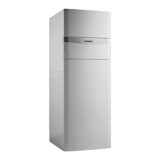
uniTOWER plus
Vaillant uniTOWER plus Manuals
Manuals and User Guides for Vaillant uniTOWER plus. We have
1
Vaillant uniTOWER plus manual available for free PDF download: Operating Instructions Manual
Vaillant uniTOWER plus Operating Instructions Manual (72 pages)
Brand:
Vaillant
| Category:
Heat Pump
| Size: 6.14 MB
Table of Contents
Operating Instructions
3
Table of Contents
3
General Safety Information
4
Safety
4
Intended Use
4
Notes on the Documentation
6
Product Description
6
Heat Pump System
6
Product Design
6
Opening the Front Flap
6
Control Elements
6
Control Panel
7
Description of the Symbols
7
Functional Description of Buttons
7
Type Designation and Serial Number
8
CE Marking
8
Benchmark
8
Safety Devices
8
Operation
8
Basic Display
8
Starting up the Product
9
Menu Display
9
Operating Concept
9
Caring for the Product
10
Maintenance
10
Setting the Domestic Hot Water Temperature
10
Care and Maintenance
10
Setting the Heating Flow Temperature
10
Switching off the Product's Functions
10
Decommissioning
11
Recycling and Disposal
11
Permanently Decommissioning the Product
11
Temporarily Decommissioning the Product
11
Detecting and Eliminating Faults
11
Troubleshooting
11
Checking the System Pressure
11
Reading Maintenance Messages
11
Reading Fault Messages
11
Guarantee and Customer Service
12
Customer Service
12
Appendix
13
A Troubleshooting
13
B Overview of the End User Level
13
Installation and Maintenance
15
General Safety Information
17
Intended Use
17
Safety
17
Regulations (Directives, Laws, Standards)
18
Further Information
19
Heat Pump System
19
Notes on the Documentation
19
Product Description
19
Safety Devices
19
Connection Symbols
20
Functional Elements
20
Information on the Data Plate
20
Serial Number
20
Benchmark
21
CE Marking
21
Compressor Hysteresis
21
Cooling Mode
21
Energy Balance Control
21
Set-Up
21
Unpacking the Product
21
Checking the Scope of Delivery
22
Permissible Height Difference between the Outdoor Unit and the Indoor Unit
22
Selecting the Installation Site
22
Dimensions
23
Minimum Clearances and Installation Clearances
23
Product Dimensions for the Transport
23
Transporting the Product
23
Separating the Product into Two Modules Where Necessary
24
Removing the Casing
25
Installing the Casing
26
Moving the Electronics Box (Optional)
27
Setting up the Indoor Unit
27
Carrying out the Installation Preparations
28
Connecting the Building Circuit
28
Connecting the Heat Pump to the Indoor Unit
28
Hydraulics Installation
28
Installing the Domestic Hot and Cold Water Connection
28
Removing the Carrying Straps
28
Hydraulic Connection
29
Installing Potable Water Pipes
29
Installing the Drain Pipe on the Expansion Relief Valve
31
Connecting Additional Components
32
Connecting the Condensate Discharge
32
Electrical Installation
32
Electrical Partition
32
Installing Components for the Energy Supply Company Lockout Function
32
Preparing the Electrical Installation
32
Requirements for the Quality of the Mains Voltage
32
Establishing the Power Supply, 1~/230V
33
Removing the Cover from the Power Supply PCB
33
Routing the Cables in the Product
33
Establishing the Power Supply, 3~/400V
34
Installing the System Control in the Electronics Box
35
Opening the Control Pcb's Electronics Box
35
Requirements for the Ebus Line
35
Routing the Cables in the Electronics Box
35
Carrying out the Wiring
36
Connecting a Limit Thermostat for the Underfloor Heating
36
Connecting the Circulation Pump
36
Connecting the Outdoor Temperature Sensor
36
Connecting the VR 70/VR 71 Mixer Module
36
Installing the Cover for the Power Supply PCB
36
Checking and Treating the Heating Water/Filling and Supplementary Water
37
Checking the Electrical Installation
37
Operating Concept of the Product
37
Operation
37
Prioritising Diverter Valve, Setting the Heating Circuit/Cylinder Charging
37
Start-Up
37
Filling and Purging the Heating Installation
38
Enabling the Electric Back-Up Heater
39
Filling the Domestic Hot Water Circuit
39
Menu Functions Without the Optional System Control
39
Purging
39
Running the Installation Assistants
39
Switching on the Product
39
Activating Cooling Mode
40
Calling up Statistics
40
Calling up the Installer Level
40
Checking Function and Leak-Tightness
40
Checking the Configuration
40
Displaying the Filling Pressure in the Building Circuit
40
Floor Drying
40
Setting the Anti-Legionella Function
40
Adapting the Unit to the Heating Installation
41
Configuring the Heating Installation
41
Instructing the End User
41
Starting up the Optional System Control
41
Total Pressure Loss in the Product, Building Circuit
41
Total Pressure Loss in the Product, Domestic Hot Water
41
10 Troubleshooting
42
Carrying out the Actuator Test
42
Contacting Your Service Partner
42
Displaying Live Monitor (Status Codes)
42
Querying the Fault Memory
42
Reading off the Fault Codes
42
Resetting the Fault Memory
42
Safety Cut-Out
42
Using the Function Menu
42
11 Inspection and Maintenance
43
Checking Maintenance Messages
43
Checking the Pre-Charge Pressure of the Expansion Vessel
43
Observing Inspection and Maintenance Intervals
43
Preparing for Inspection and Maintenance
43
Procuring Spare Parts
43
Resetting Parameters to Factory Settings
43
Using Check Programmes
43
12 Draining
44
13 Decommissioning
44
14 Recycling and Disposal
44
15 Customer Service
44
Cleaning the Domestic Hot Water Cylinder
44
Decommissioning the Product
44
Draining the Product's Domestic Hot Water Circuit
44
Draining the Product's Heating Circuit
44
A Functional Diagram
45
Appendix
45
B Wiring Diagram
46
C Control PCB
47
D Basic Connection Diagram for the Energy Supply Company Lockout, Shutdown Via Connection S21
48
E Basic Connection Diagram for the Energy Supply Company Lockout, Shutdown Via Partition
49
F Installer Level Overview
50
G Status Codes
53
H Maintenance Messages
56
I Comfort Protection Mode
56
J Fault Codes
56
K 5.4 Kw Back-Up Heater at 230 V and at
61
L Inspection and Maintenance Work
61
M Characteristic Values for the Internal Temperature Sensors, Hydraulic Circuit
61
N Characteristic Values for the VR10 Internal Temperature Sensors, Cylinder Temperature
62
O Characteristic Values for the VRC DCF Outdoor Temperature Sensor
63
Commissioning Checklist
64
Q Technical Data
67
Index
70
Advertisement
Advertisement
Related Products
Vaillant uniTOWER VWL Series
Vaillant UK aroTHERM plus
Vaillant uniSTOR
Vaillant uniSTOR VIH GB SERIES
Vaillant uniSTOR VIH RW GB BES Series
Vaillant uniSTOR HP VIH RW GB BES Series
Vaillant uniSTOR plus Series
Vaillant uniSTOR exclusive Series
Vaillant 00 2002 5744
Vaillant 0010002778
Vaillant Categories
Boiler
Water Heater
Heat Pump
Thermostat
Air Conditioner
More Vaillant Manuals
Login
Sign In
OR
Sign in with Facebook
Sign in with Google
Upload manual
Upload from disk
Upload from URL