Sign In
Upload
Manuals
Brands
Trane Manuals
Controller
Tracer UC600
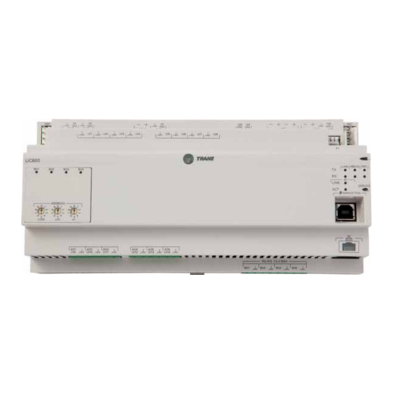
User Manuals: Trane Tracer UC600 Controller
Manuals and User Guides for Trane Tracer UC600 Controller. We have
3
Trane Tracer UC600 Controller manuals available for free PDF download: Installation, Operation And Maintenance Manual, Installation Manual, Integration Manual
Trane Tracer UC600 Installation, Operation And Maintenance Manual (84 pages)
Brand:
Trane
| Category:
Controller
| Size: 4.94 MB
Table of Contents
Table of Contents
4
Overview
7
Smoke Control Support (UUKL)
7
Air-Fi™ Wireless Communications Interface (WCI) Support
7
Expansion Module Requirements
7
Specifications
8
Location of Leds
8
Hardware Terminations
9
Agency Listings and Compliance
10
Additional Ordering Options
10
Required Tools
10
Dimensions and Clearances
11
Installation
13
Mounting and Removing the Tracer UC600 Controller
13
DIN Unit Width
13
Setting Addresses Using Rotary Switches
15
Setting the Bacnet Device ID
16
Bacnet MS/TP Device ID Assignment
16
Device ID Assignment for Bacnet/Ip Devices
17
Device ID Assignment for Wireless Devices
17
Rotary Dial Address Settings for Non-Trane Systems
17
Tracer UC600 Pre-Power Checks
18
Resistive Inputs
18
Voltage Inputs
19
Current Inputs
19
Binary Inputs
20
Power Budget Check in an Un-Powered State
21
Calculating AC Power Consumption
21
Calculating DC Power Consumption
22
Wiring and Powering the Tracer UC600
23
AC Power Warnings and Cautions
23
Requirements and Recommendations
23
Wiring and Circuit Requirements
23
Transformer Requirements
24
Avoid Equipment Damage
24
Terminal Connectors and Tug Test
24
Wiring AC Power to Tracer UC600
25
Controller Startup and Power Check
26
Bacnet MS/TP Link Wiring
27
Bacnet/Ip Wiring
27
Wiring Inputs and Outputs
28
Providing Low-Voltage Power for Inputs/Outputs
29
Input and Output Wiring
29
Wiring Universal Inputs
30
Wiring Binary Inputs
30
Wiring 0-10 VDC Analog Inputs
31
Wiring 0-20 Ma Analog Inputs
32
Wiring Variable Resistance Analog Inputs
33
Wiring Trane Zone Sensors
34
Wiring Analog Outputs
35
Wiring Binary Outputs
36
Connecting Pressure Transducer Inputs
37
Tracer UC600 Operation
38
LED Descriptions and Activities
38
Troubleshooting
39
Communication Problems
39
Output Points
39
Connection Problems
40
Configuring Tracer UC600 with Tracer TU
41
Starting a Session of TU and Connection
41
Connecting Using Tracer SC
42
Tracer TU Installation and Connection Error Conditions
44
Upgrading Firmware
45
Configuring Tracer UC600 and Creating or Editing Points
46
Configuring Tracer UC600
46
Using Pre-Packaged Solutions (PPS)
47
Creating or Editing Points for the UC600
47
Placing Points in Out-Of-Service Mode
49
Creating Points to Monitor Communication and TGP2 Programs
49
Creating Points for Timed Override (TOV) and */** Functions
50
Monitoring and Viewing the Status of the Tracer UC600
53
Backup
54
Transfer Files (Restore)
54
Setting up and Maintaining Schedules
55
Creating a Weekly Schedule
55
Changing the Schedule Default Value and Adding Events
57
Adding Exceptions to a Schedule
59
Modifying Exceptions
62
Deleting Events
62
Deleting Exceptions
63
Deleting a Schedule
63
Custom Graphics
63
Graphics Best Practices
65
Commissioning/Troubleshooting in a Powered State
66
Resistive Inputs
67
Voltage Inputs
68
Current Inputs - Methods 1 or 2
69
24 Vac Measurement
70
Binary Inputs, 24 Vac Detect- Methods 1 or 2
71
Binary Inputs- Based on Analog Output Connection
71
Open-Collector Based Binary Sensors
72
Voltage Analog Output
73
Current Analog Output- Methods 1 or 2
73
Ground Measurements
74
Other Resources
75
Appendix A: Configuring Tracer UC600 for Bacnet/Ip
76
Device ID Assignment for Trane Bacnet/Ip Devices
76
Ethernet Network Wiring Specifications
76
Bacnet/Ip Network Configuration on the Tracer SC
76
Enabling BBMD Functionality on the IP Network
77
Setting up Tracer UC600 Bacnet Communication with Tracer TU
78
Establishing a Direct Connection with Tracer TU
78
Establishing a Network Connection with Tracer TU
79
Configuring IP Information
79
Configuring Bacnet Information
80
Setting up a BDT
81
Security
81
Local Network (Firewall) Security
81
Disable HTTP Communications
82
Disable Tracer UC600 User Interface (TD7)
82
Declaration of CE Conformity
83
Advertisement
Trane Tracer UC600 Installation Manual (56 pages)
for Modular Self Contained
Brand:
Trane
| Category:
Controller
| Size: 0.6 MB
Table of Contents
Warnings, Cautions, and Notices
2
Table of Contents
4
Overview
5
Bacnet Protocol
5
UC600 Rotary Swtiches and Leds
6
Setting Addresses Using Rotary Switches
6
Location of Leds
6
Setting Rotary Switch Values on UC600
6
LED Descriptions and Activities
7
Tracer UC600 Leds
7
LED Identification and Interpretation
7
Tracer UC600 Pre-Power Checks
8
Resistive Inputs
8
Voltage Inputs
8
Current Inputs
9
Binary Inputs
9
Configuring the UC600
11
Using the Bacnet Setup Tool
11
Using Tracer TU
11
Connection
11
Configuration
11
Configuration
12
MS/TP MAC Address
13
Bacnet Device ID
14
Third-Party BAS Integration
14
Tracer SC BAS Integration
14
Example Showing Rotary Dial Settings and the Bacnet Device ID
14
BAS Unit Control
16
Routinely Updating BAS Values
16
Alarm Reset
16
Object and Diagnostic Data Points
18
Analog Inputs
18
Analog Outputs
18
Analog Values
19
Binary Outputs
23
Table 7. Binary Values
24
Multi-State Values
29
All Object Types Sorted by Object Name
32
Alarming
48
Alarm Objects
48
Additional Resources
52
Trane Tracer UC600 Integration Manual (36 pages)
For Packaged Outdoor Air Unit
Brand:
Trane
| Category:
Controller
| Size: 0.75 MB
Table of Contents
Table of Contents
4
Overview
5
Bacnet Protocol
5
Bacnet Testing Laboratory (BTL) Certification
5
UC600 Rotary Switches and Leds
6
Rotary Switches
6
Leds Description, Behavior, and Troubleshooting
6
24 Vac Measurement
7
Configuring the UC600
9
Using the Bacnet Setup Tool
9
Connection
9
Configuration
9
Using Tracer TU
9
Configuration
10
MS/TP MAC Address
10
Bacnet Device ID
10
3Rd Party BAS Integration
10
Tracer SC BAS Integration
11
BAS Unit Control
11
Initiating System Control
12
Routinely Updating BAS Values
12
Alarm Reset
12
Bacnet Data Points and Configuration Property Definitions
13
Bacnet Protocol Implementation Conformance Statement (PICS)
13
Standardized Device Profile (Annex L)
13
Interoperability Building Blocks (Annex K)
13
Segmentation Capability
14
Object Types
14
Data Link Layer Options, Device Address Binding, Network Options, and Character Sets
18
Object and Diagnostic Data Points
19
Alarming
33
Additional Resources
34
Advertisement
Advertisement
Related Products
Trane Tracer UC210
Trane Tracer UC400
Trane UG30
Trane Tracer UC400-B
Trane TRACER CH532
Trane Tracer ZN.520
Trane Tracer ZN524
Trane Tracer ZN521
Trane Tracer VV550
Trane Tracer VV551
Trane Categories
Air Conditioner
Heat Pump
Chiller
Air Handlers
Furnace
More Trane Manuals
Login
Sign In
OR
Sign in with Facebook
Sign in with Google
Upload manual
Upload from disk
Upload from URL