Sign In
Upload
Manuals
Brands
Thermo Scientific Manuals
Accessories
Heracell 240i
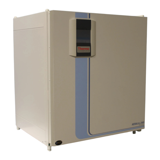
Thermo Scientific Heracell 240i Manuals
Manuals and User Guides for Thermo Scientific Heracell 240i. We have
2
Thermo Scientific Heracell 240i manuals available for free PDF download: Operating Instructions Manual
Thermo Scientific Heracell 240i Operating Instructions Manual (197 pages)
CO2-Incubator
Brand:
Thermo Scientific
| Category:
Accessories
| Size: 11.88 MB
Table of Contents
Operating Instructions
1
Table of Contents
3
Figures
6
Chapter 1 General Notes
9
Overview
9
Applicability of the Instructions
10
Identification of the Device and of the Documentation
10
Instruction of the Operating Personnel
10
Warranty
11
Correct Use
13
Intended Purpose of the Device
13
Incorrect Use
14
Standards and Directives
14
Safety Notes
15
Installation Work
16
Safety Notes on Carbon Dioxide
16
Safety Notes on Gases
16
Safety Notes on Oxygen
16
Operational Safety Rules
17
Safety Notes on Nitrogen
17
Acceptance Inspection
19
Chapter 2 Delivery of the Device
19
Packaging
19
Optional Equipment Components HERACELL
20
Standard Equipment Components HERACELL
20
Ambient Conditions
23
Chapter 3 Installation of the Device
23
Room Ventilation
24
Space Requirements
24
Accessibility of the Devices
25
Device Dimensions
25
Humidity
26
Lift Points
26
Transport
26
Stacking
27
Intermediate Storage
28
Retrofitting/Modifications
28
Chapter 4 Description of the Device
29
Front View
29
Rear View
30
Looped-Through Gas Supply
32
Safety Devices
37
Temperature
37
Work Space Atmosphere
37
Relative Humidity
38
Water Quality Recommendation
38
Door Switch
40
Sensor System
41
If the Thermal Protection Is Enabled
42
Supply Interface
43
Alarm Contact
44
Gas Connection
44
Label
44
RS 232 Interface
44
Work Space Components
45
Interior Container
46
Oxidation of Copper Components
46
Optional Split Gas-Tight Screens
47
Water Reservoir
48
Gas Humidification
49
Heating System
49
Rear Panel Openings
50
Shelf System
51
Bottle Turning Device for HERACELL
52
Water Pump
54
Let the Device Adapt to the Ambient Conditions
57
Preparing the Work Space
57
Start-Up
57
Installing the Shelf System
58
Installation/Removal of the Support Rail
59
Support Rail Installation/Removal
59
Installing the Shelf Supports
60
Leveling the Device
60
Shelf Support Installation
60
Installing the Gas Humidification
61
Installing the Bottle Turning Devices
62
Installing the Optional Bottle Turning Devices HERACELL
62
Set Speed of the Bottle Turning Device
62
Use of Diagram
62
Bottle Turning Speed
63
Center Strut Installation
64
Configuration with Split Inserts
64
Gas Connection
65
Installing Gas Pressure Hoses
65
Gas Connection Without Gas Monitoring System
66
Installing Devices Without the Optional Gas Monitoring System
66
Gas Connection with Gas Monitoring System (Optional)
67
Power Supply Connection
69
Connection to the Power Supply System
70
Connecting the Devices
71
Connecting the RS 232 Interface
71
RS-232 Interface Compatibility
71
Alarm Relay
72
Connecting the Alarm Contact
72
Connecting the USB Interface (Optional)
72
Connection Example
74
Chapter 6 Operation
75
Preparing the Device
75
Prior to Starting Operation
75
Decontaminating the Device Work Space
76
Starting Operation
76
Starting the Device
76
Duration of the Auto-Start Routine
77
Loading the Device
77
Interruption of Operation
78
Chapter 7 .......................................................Handling and Control (Icantm Touchscreen Controller)
79
Power Switch
79
Operating Panel and Operating Structure
80
Pressure-Sensitive Areas
80
Operation Is Divided into Three Levels
83
Structure of the Operating Levels
83
Heat-Up Phase Display
84
Heat-Up Phase of the Control Loop Sensors
84
Event Actions for Settings
85
Resetting the Settings
85
Saving the Settings
85
Setting the Temperature Set Value
86
To Accept and Save the Set Value
87
To Reduce the Set Value
87
Gas Monitoring
89
Auto-Start Routine
91
Usage of the Process Gases
91
Conditions that Prevent the Start of the Auto-Start Routine
92
Duration of the Routine
92
Start Conditions for the Auto-Start Routine
92
Auto-Start-Dry Execution of Auto-Start Routine
93
Faulty Cancellation of the Auto-Start Routine
93
Activating Auto Start
94
Auto-Start Routine Activation
94
Preparations for the Start
94
Automatic Restart
95
Interrupting the Auto-Start Routine
96
To Cancel the Auto-Start Routine
96
To Resume the Auto-Start Routine
96
Running the Contra-Con Routine
97
Settings
97
To Accept the Failure Message
97
User Configuration
97
Changing the Code
98
Changing the Keypad Lock Code
98
Entering the New 4-Digit Code
99
To Set the Cursor to the Left to Overwrite a Value
99
Date / Time Setting
100
Setting Date/Time
100
Display Contrast Setting
101
Setting the Contrast
101
To Increase the Value
101
Setting the Key Tone
102
RS 232 Interface Baud Rate Setting
103
Setting the Interface Baud Rate
103
USB Interface Baud Rate Setting
103
Setting the User Display Screen Language
104
To Browse Downward in the Selection
104
To Browse Upward in the Selection
104
Reminder Interval Setting
105
Setting the Reminder Intervals
105
Event Display
107
Event Logging
107
Changing the Logging Cycle Time
108
Logging Cycle Setting
108
Displaying the Error Table
109
Error Table Display
109
Alarm Relay Setting
110
Options
110
Setting the Alarm Relay
110
Low Humidity Setting
111
Setting Low Humidity
111
Gas Tight Screen
112
Setting the Gas-Tight Screen
112
Switching the Audible Alarm On/Off
113
Switching the Water Level Sensor On/Off
113
Water Level Setting
113
Setting the Bottle Turning Device Speed
114
Bottle Turning Device Speed Setting
115
Airing the Work Space
117
Icon Description
118
Icon Description Overview
118
Bottle Turning Device
119
Function of the Individual Icons
119
Low Humidity
119
Low Water Level
119
Gas Cylinder Filling Level Display
120
Gas Monitoring Icons
120
If both Bottles Are Empty
120
If One Cylinder Is Empty
120
Enabling/Disabling the Keypad Lock
121
Software Versions
122
To Exit the Display
122
Full Screen Display
123
Scaling the Trend Display
123
To Display an Enlarged Section
123
Trend Display Scaling
123
Error Messages
124
Logging Cycle
124
Resetting the Code
124
To Return to the Total Trend
124
Event Error Messages
125
Response to an Error Message Event
125
Event Error Overtemperature
126
Resetting the Overtemperature Protection Mechanism
126
Troubleshooting
127
Error Message Overview
128
Shut-Down
132
Shutting the Device down
132
Cleaning
133
Cleaning Display
133
Cleaning Exterior Surfaces
133
Decontamination Procedures
133
Preparing the Manual Wipe/Spray Disinfection
134
Wipe/Spray Disinfection
134
Predisinfection
135
Cleaning the Work Space and Accessories
136
Final Disinfection
136
Removing Accessories and Shelf System
136
Removing Blower Wheel and Cover
136
Contra-Con Decontamination Routine
137
Overtemperature Protection
137
Procedure of a Contra-Con Decontamination Routine
138
Condensation
139
Decontamination Phase
139
Operating Phases of Contra-Con Decontamination
139
The Routine Is Divided into Five Phases
139
Activating Contra-Con
140
Activating the Contra-Con Routine
140
Interrupting / Canceling Contra-Con
142
Interrupting Contra-Con
142
Contra-Con Interruption Due to Error
143
To Confirm the Audible Alarm
143
To Interrupt Contra-Con from the Status Display
143
To Resume Contra-Con
143
Completing Contra-Con
144
Contra-Con Completion
144
To Stop Contra-Con
144
Annual Inspection
145
Daily Check
145
Inspections and Checks
145
Maintenance
145
Equipment Log Book
146
Preparing the Temperature Calibration
146
Returns for Repair
146
Comparison Measurement Procedure
148
Temperature Calibration Procedure
148
Temperature Calibration Procedure
149
Preparing the CO2 Calibration
150
Suitable Instrument
150
To Accept and Store the Targeting Value
150
Gas-Tight Screen Measurement Opening
152
IR Measuring Cell
153
CO2 Calibration
154
Measurement Example
155
Replacing the Gas Inlet Filter
155
Gas Inlet Filter Installation
156
Procedure for All Gas Inlet Filters
156
Procedure for Gas Supply Gas Inlet Filter
156
Replacing the Device Fuses
156
Device Fuse Replacement
157
Replacing the Door Seal
157
Magnetic Door Seal Replacement
158
Chapter 11 Disposal
159
Overview of the Material Used
159
Chapter 12 Technical Data
161
Data Communication
165
HERACELL® 150I
165
Interfaces
165
Chapter 13 Data Communication
166
Installing the USB Port Driver
166
Interfaces
167
Character Coding
168
Communication
168
Description of the Protocol
168
Description of the Response Elements
168
Reading Parameters
168
Overview of General Parameters (Addresses 0Xxx)
169
Reading General Parameters
169
Response with an Error Message
169
Overview of Incubator Parameters (Addresses 2Xxx)
170
Reading Basic Parameters
170
Reading Internal Function Parameters
170
Error Memory Structure
172
Overview of the Possible Error Messages in Bit Coding
173
Overview of the Possible Error Messages in Hex Coding
173
Data Logger Structure
175
Example of a Response
175
Data Logger Data Set Structure Scheme
176
Overview of Possible Event Entries in Bit Coding
177
Examples of Data Logger Codes
178
Example of a Code for a a Data Logger Query
179
Functions for Data Logger Queries
179
Installing the HERACELL
185
Program HERACELL
185
Starting the Installation Routine
185
In the Sequence of the Given Installation Steps
186
MAIN with Two Functional Elements
186
Operating the HERACELL
186
User Menu Structure
186
Presetting
187
Date & Time
188
Test Com
188
Error Logger
189
Data Logger
190
Servicefile
191
Password
192
Device Log
193
Advertisement
Thermo Scientific Heracell 240i Operating Instructions Manual (156 pages)
CO2 Incubator with Decontamination Routine
Brand:
Thermo Scientific
| Category:
Accessories
| Size: 9.56 MB
Table of Contents
Table of Contents
3
1 General Notes
9
Identification of the Device and of the Documentation
10
Instruction of the Operating Personnel
10
Applicability of the Instructions
11
Warranty
11
Explanation of Safety Information and Symbols
12
Safety Information and Symbols Used in the Operating Instructions
12
Additional Symbols for Safety Informations
12
Symbols on the Device
13
Intended Purpose of the Device
14
Correct Use
14
Incorrect Use
14
Standards and Directives
15
Safety Notes on Gases
16
Safety Notes on Carbon Dioxide (CO )
16
Safety Notes on Oxygen (O )
17
Safety Notes on Nitrogen (N )
17
2 Delivery of the Device
18
Packaging
18
Acceptance Inspection
18
Standard Equipment Components Heracell ® 150I
19
Optional Equipment Components Heracell ® 150I
19
Standard Equipment Components Heracell ® 240I
20
Optional Equipment Components Heracell ® 240I
21
3 Installation of the Device
22
Ambient Conditions
22
Room Ventilation
22
Space Requirements
23
Fig. 1: Device Dimensions
23
Transport
24
Stacking
24
Fig. 2: Lift Points
24
Fig. 3: Stacking
24
Retrofitting/Modifications
25
4 Description of the Device
26
Front View of Heracell ® 150I
26
Fig. 4: Front View Heracell ® 150I
27
Rear View Heracell ® 150I
28
Fig. 5: Rear View Heracell ® 150I
29
Fig. 6: Looped-Through Gas Supply Heracell ® 150I
31
Front View Heracell ® 240I
32
Fig. 7: Front View Heracell ® 240I
33
Rear View Heracell ® 240I
34
Fig. 8: Rear View Heracell ® 240I
35
Fig. 9: Looped-Through Gas Supply Heracell ® 240I
37
Safety Devices
38
Work Space Atmosphere
38
Door Switch
40
Fig. 10: Door Switch
40
Sensor System
41
Fig. 11: Temperature, CO 2 ,And O 2 Sensors
41
Supply Interface
42
Fig. 12: Supply Interface
42
Work Space Components
44
Interior Container
44
Optional Split Gas-Tight Screens
44
Fig. 13: Work Space Components
44
Water Reservoir
45
Gas Humidification (Optional, Only for O Control)
45
Fig. 14: Water Reservoir
45
Rear Panel Openings
46
Fig. 15: Rear Panel Openings
46
Shelf System
47
Bottle Turning Device for Heracell® 240I (Optional)
47
Fig. 16: Bottle Turning Device
47
Water Pump
48
Fig. 17: Water Pump
48
5 Start-Up
49
Preparing the Work Space
49
Installing the Shelf System
49
Installation/Removal of the Support Rail
49
Fig. 18: Support Rail Installation/Removal
49
Installing the Shelf Supports
50
Levelling the Device
50
Installing the Gas Humidification (Optional, Only for O -Control)
50
Fig. 19: Shelf Support Installation
50
Fig. 20: Installing Gas Humidification
50
Installing the Optional Bottle Turning Devices Heracell 240I
51
Fig. 21: Installing the Bottle Turning Devices
51
Fig. 22: Bottle Turning Speed
53
Installing the Optional Center Strut Heracell ® 240I for Split Inserts
54
Fig. 23: Center Strut Installation
54
Gas Connection
55
Installing Gas Pressure Hoses
55
Fig. 24: Installing Gas Pressure Hoses
55
Installing Devices Without the Optional Gas Monitoring System
56
Fig. 25: Gas Connection Without Gas Monitoring System
56
Combined CO Connection with Gas Monitoring System (Optional)
57
Connection with Gas Monitoring System (Optional)
57
Fig. 26: Gas Connection with Gas Monitoring System (Optional)
57
Fig. 27: Combined Connection with Gas Monitoring System (Optional)
58
Power Supply Connection
59
Fig. 28: Combined Gas Connection with Gas Monitoring System
59
Fig. 28: Power Supply Connection
59
Connecting the RS 232 Interface
60
Connecting the USB Interface (Optional)
60
Connecting the Alarm Contact
61
Fig. 29: Connection Example
62
6 Operation
63
Preparing the Device
63
Starting Operation
64
7 Handling and Control (Ican™ Touchscreen Controller)
65
Power Switch
65
Operating Panel and Operating Structure
65
Fig. 30: Power Switch
65
Fig. 31: Pressure-Sensitive Areas
65
Fig. 32: Ican™ Touchscreen Withouto 2 /N 2 Gas Supply
66
Fig. 33: Ican™ Touchscreen with Combined Gas Connection
66
Fig. 34: Menu Structure Overview
67
Factory Presettings of the Ican™ Touchscreen Controls
68
Heat-Up Phase of the Control Loop Sensors
68
Fig. 35: Heat-Up Phase Display
68
Event Actions for Settings
69
Setting the Temperature Set Value
70
Fig. 36: Setting the Temperature Set Value
70
Setting the CO Set Value
71
Fig. 37: Setting the CO Set Value
71
Setting the O Set Value
72
Fig. 38: Setting the O 2 Set Value
72
Auto-Start Routine
73
Activating Auto-Start
75
Fig. 39: Activating the Auto-Start Routine
75
Interrupting the Auto-Start Routine
76
Running the Contra-Con Routine
76
User Configuration
76
Fig. 40: Interrupting the Auto-Start Routine
76
Settings
77
Fig. 41: Changing the Code
77
Fig. 42: Date / Time Setting
78
Fig. 43: Display Contrast Setting
79
Fig. 44: Key Tone Setting
79
Fig. 45: RS 232 Interface Baud Rate Setting
80
Fig. 46: USB Interface Baud Rate Setting
80
Fig. 47: Language Setting
81
Fig. 48: Reminder Interval Setting
82
Event Logging
83
Fig. 49: Event Display
83
Fig. 50: Logging Cycle Setting
83
Fig. 51: Error Table Display
84
Options
85
Fig. 52: Alarm Relay Setting
85
Fig. 53: Low Humidity Setting
86
Fig. 54: Gas Tight Screen Setting
87
Fig. 55: Water Level Setting
87
Fig. 56: Alarm Relay Setting
88
Fig. 57: Bottle Turning Device Speed Setting
88
Fig. 58: Switching the O 2 Control on and off
89
Icon Description
90
Fig. 59: Icon Description Overview
90
Fig. 60: Gas Monitoring Icons
91
Enabling/Disabling the Keypad Lock
92
Fig. 61: Enabling/Disabling the Keypad Lock
92
Software Versions
93
Fig. 62: Software Versions
93
Scaling the Trend Display
94
Fig. 63: Trend Display Scaling
94
Error Messages
95
Response to an Error Message Event
95
Troubleshooting
95
Fig. 64: Event Error Messages
95
8 Shut-Down
99
Shutting the Device down
99
9 Cleaning and Disinfection
100
Cleaning
100
Decontamimation Procedures
101
Wipe/Spray Disinfection
101
Contra-Con Decontamination Routine
104
Fig. 65: Decontamination Routine Phases
106
Activating the Contra-Con Routine
107
Interrupting Contra-Con
107
Fig. 66: Activating Contra-Con
107
Contra-Con Interruption Due to Error
108
Fig. 67: Interrupting / Cancelling Contra-Con
108
Completing Contra-Con
109
Fig. 68: Contra-Con Completion
109
10 Maintenance
110
Inspections and Checks
110
Service Intervals
110
Preparing the Temperature Calibration
111
Fig. 69: Preparing the Temperature Calibration
111
Temperature Calibration Procedure
112
Fig. 70: Temperature Calibration Procedure
112
Preparing the CO Calibration
113
Fig. 71: Preparing CO 2 Calibration
113
Fig. 72: Gas-Tight Screen Measurement Opening
114
CO Calibration Procedure
115
Fig. 73: CO 2 Calibration Procedure
115
Replacing the Gas Inlet Filter
116
Replacing the Device Fuses
116
Fig. 74: Gas Inlet Filter Installation
116
Fig. 75: Device Fuse Replacement
116
Replacing the Door Seal
117
Fig. 76: Magnetic Door Seal Replacement
117
11 Disposal
118
12 Technical Data
120
13 Annex: Data Communication
124
Interfaces
124
RS 232 Interface
124
USB Port (Optional)
124
Installing the USB Port Driver
125
Structure of the Command Sequences for Data Communication
127
Description of the Protocol
127
Overview of General Parameters (Addresses 0Xxx)
128
Reading General Parameters
128
Overview of Incubator Parameters (Addresses 2Xxx)
129
Reading Basic Parameters
129
Reading Internal Function Parameters
130
Error Memory Structure
132
Error Memory Data Set Structure Scheme
133
Overview of the Possible Error Messages in Hex Coding
133
Overview of the Possible Error Messages in Bit Coding
134
Data Logger Structure
136
Data Logger Data Set Structure Scheme
137
Overview of Possible Event Entries in Bit Coding
138
Examples of Data Logger Codes
140
Functions for Data Logger Queries
140
Example of a Code for a a Data Logger Query
140
Program Heracell 150I & 240I
145
Installing the Heracell 150I & 240I
146
Operating the Heracell 150I & 240I
147
14 Device Log
154
Advertisement
Related Products
Thermo Scientific Heracell Vios 250i CR
Thermo Scientific HERACELL VIOS 250i
Thermo Scientific 2076 Series
Thermo Scientific 2862
Thermo Scientific 2863 253
Thermo Scientific Heracell 150i
Thermo Scientific Heracell Vios 160i CR
Thermo Scientific HERACELL VIOS 160i
Thermo Scientific Heracell 240i GP
Thermo Scientific 2840
Thermo Scientific Categories
Laboratory Equipment
Measuring Instruments
Accessories
Freezer
Refrigerator
More Thermo Scientific Manuals
Login
Sign In
OR
Sign in with Facebook
Sign in with Google
Upload manual
Upload from disk
Upload from URL