Sign In
Upload
Manuals
Brands
Tektronix Manuals
Test Equipment
MSO58
Tektronix MSO58 Manuals
Manuals and User Guides for Tektronix MSO58. We have
6
Tektronix MSO58 manuals available for free PDF download: Programmer's Manual, Printable Help, Installation And Safety Manual, Service Manual, Declassification And Security Instructions
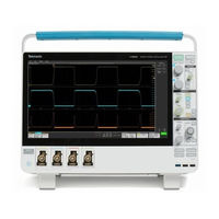
Tektronix MSO58 Programmer's Manual (1026 pages)
5 Series MSO
Brand:
Tektronix
| Category:
Test Equipment
| Size: 5.8 MB
Table of Contents
Table of Contents
5
Preface
7
Getting Started
9
Setting up Remote Communications Hardware
9
Ethernet
9
Usb
10
Setting up Remote Communications Software
11
Using VISA
11
Using the LXI Web Page and E*Scope
12
Using a Socket Server
13
Documentation
15
Dynamic Programmatic Interface
15
Implicit Activation
15
Creating, Deleting, and Listing Dynamic Instances
16
Command Syntax
17
Command and Query Structure
17
Clearing the Oscilloscope
19
Command Entry
19
Constructed Mnemonics
21
Argument Types
23
Command Groups
27
Acquisition Command Group
27
AFG Command Group
28
Alias Command Group
29
Bus Command Group
30
Calibration Command Group
35
Cursor Command Group
36
Digital Command Group
42
Display Control Command Group
44
DVM Command Group
47
Ethernet Command Group
47
File System Command Group
49
Horizontal Command Group
51
Math Command Group
53
Measurement Command Group
55
Miscellaneous Command Group
69
Plot Command Group
71
Power Command Group
71
Save and Recall Command Group
78
Save on Command Group
79
Search and Mark Command Group
80
Self Test Command Group
90
Status and Error Command Group
91
Trigger Command Group
92
Vertical Command Group
101
Waveform Transfer Command Group
104
Zoom Command Group
108
Commands Listed in Alphabetical Order
109
Status and Events
917
Queues
920
Event Handling Sequence
921
Synchronization Methods
923
Advertisement
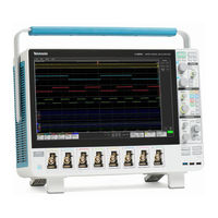
Tektronix MSO58 Printable Help (518 pages)
Brand:
Tektronix
| Category:
Test Equipment
| Size: 10.05 MB
Table of Contents
Table of Contents
3
Welcome to the Instrument Help
19
Product Documents and Support
21
Related Documents
21
Product Support and Feedback
23
General Information
23
Accessories
25
Standard Accessories
25
Recommended Accessories
26
Recommended Probes
27
Options
29
Bandwidth Options
29
Record Length Options
31
Microsoft Windows 10 Operating System Option
32
Arbitrary Function Generator (AFG) (Optional)
33
Enhanced Instrument Security (Factory Option)
34
Serial Bus and Trigger Options
34
Tektronix Software License Agreement
35
Compliance Testing Options
35
Advanced Jitter Analysis Option
36
Advanced Power Analysis Option
36
Power Cord Options
37
Service Options
37
How to Install an Option License
38
How to Uninstall (Return) an Option License
40
Install Your Instrument
43
Check Shipped Accessories
43
Safely Rotate the Handle
44
Operating Requirements
45
Input Signal Requirements
45
Power Requirements
45
Powering the Oscilloscope
46
Check that Oscilloscope Passes Power-On Self Tests
47
Installing and Activating Windows 10 Option
47
Install the Windows SSD Drive
47
Powering on Windows for the First Time
49
Activating Windows
49
Differences between Windows and Base Instrument User Interfaces
50
Updating the Windows Tekscope Application Software
50
Secure (Lock) the Oscilloscope
51
Connecting Probes
51
Rackmount Information
53
Getting Acquainted with Your Instrument
55
Front Panel Controls and Connectors
55
MSO58LP Front Panel Controls and Connections
64
Rear Panel Connections
66
The User Interface Screen
67
The User Interface Elements
68
Badges
72
Moving Waveform and Measurement Badges
78
Configuration Menus
79
The Zoom User Interface Elements
80
Using the Touch Screen Interface for Common Tasks
81
Accessing Application Help
83
Configure the Instrument
85
Set the Time Zone and Clock Readout Format
85
Functional Check
85
Download and Install the Latest Firmware
86
Run Signal Path Compensation (SPC)
87
Trimode Probe DC Compensation
87
Compensate the Probe
88
Compensate the TPP0500B or TPP1000 Probes
91
Compensate Passive Probes
93
Connect to a Network (LAN)
93
Mount a Network Drive from a Standard Instrument
94
Mount a Network Drive from a Windows 10 Instrument
95
Unmount a Network Drive
95
Connect the Oscilloscope to a PC Using a USB Cable
95
Remote Access from a Web Browser
96
Remote Access to a Windows 10 Instrument
97
Install Tightvnc on the Windows 10 Instrument
97
Install Tightvnc on a PC
98
Deskew Analog Input Channels - Quick Visual Method
98
Deskew Analog Input Channels - Measurement Method
99
Deskew Analog Input Channels - TEK-CDA Method
100
Connect a Keyboard or Mouse
100
Connect an External Monitor or Projector
100
Prevent ESD Guidelines
100
Analog Channel Operating Basics
103
Acquiring a Signal
103
Quickly Display a Waveform (Autoset)
103
Set Horizontal Parameters
105
How to Trigger on a Signal
105
Set the Acquisition Mode
107
Start and Stop an Acquisition
108
Add a Channel Waveform to the Display
108
Configure Channel and Waveform Settings
109
Add a Math, Reference, or Bus Waveform
113
Add a Measurement
114
Configure a Measurement
117
Delete a Measurement or Search Badge
118
Add a Plot of a Measurement
118
Display a Histogram Plot
120
Display a Time Trend Plot
120
Display a Spectrum Plot
121
Display an XY or XYZ Plot
121
Display an FFT Math Waveform
121
Display a BH Curve Plot for Magnetic Property Measurement (Optional)
122
Display an I Vs (Integral Of) V Plot for I Vs V Measurement (Optional)
122
Display an Inductance Curve Plot for Inductance Measurement (Optional)
122
Display a Safe Operating Area (SOA) Measurement and Plot (Optional)
122
Display a Power Switching Loss (SWL) Trajectory Plot (Optional)
123
Display Instantaneous Power and Energy Plots from the Power Quality Measurement. (Optional)
123
Display a Harmonics Bar Graph Plot for the Power Harmonics Measurement (Optional)
123
Add a Search
124
Change Waveform View Settings
125
Display and Configure Cursors
126
Using Default Setup
128
Using Fast Acq
128
Add a Note to a View
129
Delete a Note
130
Acquiring Digital Signals
131
Connect and Set up Digital Signals
131
Add a Serial Bus to the Waveform View
132
Add a Parallel Bus to the Waveform View
134
Advanced Triggering
137
Triggering Concepts
137
Trigger on a Pulse Width Event
138
Set Trigger Holdoff
139
Trigger on Sequential Events (a and B Triggers)
139
Set up Trigger on a Parallel Bus
140
Set up Trigger on a Serial Bus
140
Trigger Using the AUX Input
141
Create Visual Trigger Areas
141
Edit Visual Trigger Areas on the Screen
142
Edit Visual Trigger Areas Using the Area Menu
145
Setting Waveform Display Parameters
149
Set Waveform Display Mode (Stacked or Overlay)
149
Set the Waveform Interpolation Mode
149
Set the Waveform Persistence, Style, and Intensity
150
Set the Graticule Style and Intensity
150
Zooming on Waveforms
151
Turn on Zoom Mode
151
Using Wave Inspector Front-Panel Controls for Zoom
152
Zoom Mode and Searches
152
Customizing Measurements
155
Label a Measurement
155
Set Measurement Reference Levels
156
Set Measurement Gates
157
Set Measurement Filters
157
Set Measurement Limits
158
Saving and Recalling Information
159
Save a Screen Image
159
Save a Waveform to a File
160
Save Instrument Settings to a File
160
Save Reports
161
Save Sessions
162
Recall a Reference Waveform
163
Recall a Setup File
163
Recall a Session File
164
Menus and Dialog Boxes
165
The Acquisition Configuration Menu
165
Save on Trigger Menu
166
Fastframe Panel
167
Fastframe Badge
168
Fastframe Badge Configuration Menu
170
Add Measurements Configuration Menu Overview
171
The Standard Measurements Tab
172
Amplitude Measurements Panel
172
Timing Measurements Panel
174
Jitter Measurements Panel
176
The Jitter Tab (Advanced Jitter and Eye Analysis) (Optional)
177
The Power Tab (Optional)
181
Measurement Configuration Menu Overview
184
Measurement Name Panel (Measurement Configuration Menu)
185
Configure Panel (Measurement Configuration Menu)
185
Reference Levels Panel (Measurement Configuration Menu)
186
Clock Recovery Panel (Measurement Configuration Menu)
188
Clock Recovery- Advanced Settings Configuration Menu
192
Gating Panel (Measurement Configuration Menu)
193
Filter/Limit Results Panel (Measurement Settings Menu)
194
Power Measurement Configuration Menu Overview (Optional)
195
Power Measurement Name Panel (Measurement Configuration Menu)
195
Configure Panel (Power Measurement Configuration Menu)
196
Power Autoset Button
205
Power Sequence Setup Button
206
SOA Mask Definition Controls and Fields
207
Save Mask Menu (SOA Power Measurement)
208
Recall Mask Menu (SOA Power Measurement)
208
Reference Levels Panel (Power Measurement Configuration Menu)
210
Gating Panel (Power Measurement Configuration Menu)
211
Bus Configuration Menu
211
ARINC 429 Serial Bus Menu
212
Audio Serial Bus Configuration Menu
214
CAN Serial Bus Configuration Menu
216
Ethernet Serial Bus Menu
218
Flexray Serial Bus Configuration Menu
220
I2C Serial Bus Configuration Menu
222
LIN Serial Bus Configuration Menu
224
MIL-STD-1553 Serial Bus Menu
225
Parallel Bus Configuration Menu
227
Parallel Bus - Define Inputs Menu
228
RS232 Serial Bus Menu
229
SENT Serial Bus Configuration Menu
231
SPI Serial Bus Configuration Menu
233
SPMI Serial Bus Configuration Menu
235
USB Serial Bus Configuration Menu
237
Add Plot Configuration Menu
239
Add Results Table Configuration Menu
240
Results Tables Operations Overview
241
Measurement Table Configuration Menu
241
Save as Configuration Menu (Measurement Results Table)
243
Search Results Table Menu
244
Bus Decode Results Table Configuration Menu
245
Save as Configuration Menu (Bus Decode Results Table)
246
Harmonics Results Table Configuration Menu (Optional)
247
Save as Configuration Menu (Harmonics Results Table)
247
Annotation and Navigation on Waveform Plots/Data and Results Table (Optional)
248
Navigation on Bar Graph and Harmonics Results Table (Optional)
249
Search Configuration Menu Overview
249
Bus Search Configuration Menus
250
ARINC 429 Serial Bus Search Configuration Menu
251
Audio Serial Bus Search Configuration Menu
253
CAN Serial Bus Search Configuration Menu
254
Ethernet Serial Bus Search Configuration Menu
255
Flexray Serial Bus Search Configuration Menu
257
I2C Serial Bus Search Configuration Menu
259
LIN Serial Bus Search Configuration Menu
260
MIL-STD-1553 Serial Bus Search Configuration Menu
261
Parallel Bus Search Configuration Menu
263
Serial Bus Search Configuration Menu
263
SENT Serial Bus Search Configuration Menu
264
SPI Serial Bus Search Configuration Menu
266
SPMI Serial Bus Search Configuration Menu
267
USB Serial Bus Search Configuration Menu
268
Edge Search Configuration Menu
270
Logic Search Configuration Menu
271
Logic Search - Define Inputs Configuration Menu
273
Pulse Width Search Configuration Menu
273
Rise/Fall Time Search Configuration Menu
275
Runt Search Configuration Menu
277
Setup and Hold Search Configuration Menu
278
Setup and Hold Search - Define Inputs Configuration Menu
280
Timeout Search Configuration Menu
280
Window Search Configuration Menu
282
Analog Channel Configuration Menu
284
Probe Setup Panel (Channel Configuration Menu)
285
Unsupported Probe Dialog
287
Probe Compensation Configuration Menu (Analog Channels Probe Setup Panel)
287
TDP7700 Probe Compensation Menu (Analog Channels Probe Setup Panel)
288
Other Panel (Channel Configuration Menu)
288
Deskew Configuration Menu (Other Panel, Channel Configuration Menu)
289
AFG Configuration Menu
291
Cursor Configuration Menu
292
Date and Time Configuration Menu
294
Digital Channel Configuration Menu
294
Draw a Box Menu
295
DVM Configuration Menu
295
Menu Bar Overview
297
Recall Configuration Menu (File Menu)
298
Save as Configuration Menu (File Menu)
300
Browse Save as Location Configuration Menu
304
File Utilities Configuration (File Menu)
306
Mount Network Drive Configuration Menu
308
Undo, Redo (Edit Menu)
309
Application (Menu Bar)
309
User Preferences (Utility Menu)
309
I/O (Utility Menu)
313
LAN Reset Configuration Menu (Utility > I/O Menu)
316
Self Test Configuration Menu (Utility Menu)
317
Calibration Configuration Menu (Utility Menu)
318
Security Configuration Menu for Standard Instruments (Utility Menu)
318
Teksecure Erase Memory
319
Security Configuration Menu (Optional)
319
Enter Password Configuration Menu (Optional)
320
Set Password Configuration Menu (Optional)
321
Change Password Configuration Menu (Optional)
322
Demo (Utility Menu)
322
Help
323
User Interface Tutorial (Help Menu)
323
About (Help Menu)
323
Location to Save Exit Key Configuration Menu
324
Browse License Files Menu (Help > About)
326
Horizontal Configuration Menu
328
Math Configuration Menu Overview
330
Math Configuration Menu
330
Equation Editor (Math Configuration Menu)
332
Add Filter Menu (Math Equation Editor)
333
Add Variable Menu (Math Equation Editor)
334
Add Functions (Math Equation Editor)
335
Font Color Menu (Text Settings Configuration)
337
Text Settings Configuration Menu (Note and Waveform Labels Text)
337
Plot Configuration Menus
337
Eye Diagram Plot Configuration Menu
338
Fastframe Timestamp Trend Plot Configuration Menu
339
Math FFT Plot Configuration Menu (Math Waveform)
340
Histogram Plot Configuration Menu
343
Bathtub Plot Configuration Menu
344
Spectrum Plot Configuration Menu
345
Trend Plot Configuration Menu
347
Plot XY Configuration Menu
348
XYZ Plot Configuration Menu
348
Harmonics Bar Graph Plot Configuration Menu (Optional)
349
Inductance Curve Configuration Menu (Magnetic Analysis Power Measurement) (Optional)
350
BH Curve Configuration Menu (Magnetic Analysis Power Measurement) (Optional)
351
I Vs (Integral Of) V Plot Configuration Menu (Magnetic Analysis Power Measurement) (Optional)
353
Power Plots and Cursors
354
SOA Plot Configuration Menu (Optional)
355
Trajectory Plot Configuration Menu (Switching Loss Power Measurement) (Optional)
356
Save as Configuration Menu (Plot Save Panel, Save Plot Image Button)
357
Save as Configuration Menu (Plot Save Panel, Save Plot Data Button)
357
Reference Waveform Configuration Menu
358
Recall Configuration Menu (Ref Waveform Configuration Menu)
359
Search Configuration Menu
361
Trigger Configuration Menu Overview
361
Bus Trigger Configuration
362
ARINC 429 Serial Bus Trigger Settings Panel
363
Audio Serial Bus Trigger Settings Panel
366
CAN Serial Bus Trigger Settings Panel
368
Ethernet Serial Bus Trigger Settings Panel
370
Flexray Serial Bus Trigger Settings Panel
373
I2C Serial Bus Trigger Settings Panel
376
LIN Serial Bus Trigger Settings Panel
378
MIL-STD-1553 Serial Bus Trigger Settings Panel
380
Parallel Serial Bus Trigger Settings Panel
383
Serial Bus Trigger Settings Panel
385
SENT Serial Bus Trigger Settings Panel
387
SPI Serial Bus Trigger Settings Panel
390
SPMI Serial Bus Trigger Settings Panel
392
USB Serial Bus Trigger Settings Panel
395
Edge Trigger Configuration Menu
398
Logic Trigger Configuration Menu
400
Logic Trigger - Define Inputs Configuration Menu
403
Pulse Width Trigger Configuration Menu
403
Rise/Fall Time Trigger Configuration Menu
406
Runt Trigger Configuration Menu
408
Sequence Trigger Configuration Menu
411
A Trigger Event Configuration Menu
414
B Trigger Event Configuration Menu
414
Setup and Hold Trigger Configuration Menu
415
Setup and Hold Trigger - Define Inputs Configuration Menu
417
Timeout Trigger Configuration Menu
417
Logic Qualification - Define Inputs Configuration Menu
420
Window Trigger Configuration Menu
421
Visual Trigger Panel
424
Virtual Keyboard
425
Bus Trigger Radix-Specific Virtual Keypads
425
Virtual Keypad
426
Visual Trigger Area Configuration Menu
426
Visual Trigger Area Combinatorial Logic Menu
428
Right Click Menu Functions Associated with Visual Trigger Areas
429
Waveform View Configuration Menu
429
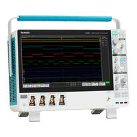
Tektronix MSO58 Printable Help (466 pages)
MSO 5 series Low Profile Mixed Signal Oscilloscope
Brand:
Tektronix
| Category:
Test Equipment
| Size: 9.11 MB
Table of Contents
Table of Contents
3
Welcome to the 5 Series MSO Help
17
Product Documents and Support
19
Related Documents
19
Product Support and Feedback
20
Accessories
21
Standard Accessories
21
Recommended Accessories
22
Recommended Probes
23
Options
25
Bandwidth Options
25
Record Length (Options 5-RL-125M, SUP5-RL-125M)
26
Microsoft Windows 10 Operating System (Option 5-WIN or SUP5-WIN)
27
Arbitrary Function Generator (AFG) (Option 5-AFG or Upgrade SUP5-AFG)
27
Enhanced Instrument Security (Option 5-SEC)
28
Serial Bus and Trigger Options
29
Compliance Testing Options
30
Advanced Jitter Analysis (Options 5-DJA, SUP5-DJA)
30
Advanced Power Analysis (Option 5-PWR, SUP5-PWR, or 5-PS2)
31
Power Cord Options
32
Service Options
32
How to Install an Option License
33
How to Uninstall (Return) an Option License
35
Install Your Instrument
37
Check Shipped Accessories
37
Safely Rotate the Handle
38
Operating Requirements
38
Input Signal Requirements
39
Powering the Oscilloscope
40
Check that Oscilloscope Passes Power-On Self Tests
41
Installing and Activating Windows 10 (Option 5-WIN, SUP5-WIN)
41
Install the SUP5-WIN SSD Drive
41
Powering on Windows for the First Time
42
Activating Windows
43
Differences between Windows and Base Instrument User Interfaces
44
Updating the Windows Tekscope Application Software
44
Secure (Lock) the Oscilloscope
45
Connecting Probes
45
Rackmount Information
47
Getting Acquainted with Your Instrument
49
Front Panel Controls and Connectors
49
MSO58LP Front Panel Connections
56
Rear Panel Connections
58
The User Interface Screen
59
The User Interface Elements
60
Badges
63
Moving Waveform and Measurement Badges
69
Configuration Menus
70
The Zoom User Interface Elements
71
Using the Touch Screen Interface for Common Tasks
72
Accessing Application Help
74
Configure the Instrument
75
Set the Time Zone and Clock Readout Format
75
Functional Check
75
Download and Install the Latest Firmware
76
Run Signal Path Compensation (SPC)
77
Compensate the TPP0500B or TPP1000 Probes
77
Compensate Passive Probes
79
Connect to a Network (LAN)
80
Connect the Oscilloscope to a PC Using a USB Cable
80
Remote Access from a Web Browser
81
Deskew Analog Input Channels - Quick Visual Method
81
Deskew Analog Input Channels - Measurement Method
82
Connect a Keyboard or Mouse
83
Connect an External Monitor or Projector
83
Prevent ESD Guidelines
83
Analog Channel Operating Basics
85
Acquiring a Signal
85
Quickly Display a Waveform (Autoset)
85
Set Horizontal Parameters
87
How to Trigger on a Signal
87
Set the Acquisition Mode
89
Start and Stop an Acquisition
90
Add a Channel Waveform to the Display
90
Configure Channel and Waveform Settings
91
Add a Math, Reference, or Bus Waveform
95
Add a Measurement
96
Configure a Measurement
98
Delete a Measurement or Search Badge
99
Add a Plot of a Measurement
100
Display a Histogram Plot
102
Display a Time Trend Plot
102
Display a Spectrum Plot
102
Display an XY or XYZ Plot
103
Display an FFT Math Waveform
103
Display an I Vs (Integral Of) V Plot for I Vs V Measurement (Option 5-PWR, SUP5-PWR, or 5-PS2 Only)
104
Display a Power Switching Loss (SWL) Trajectory Plot (Option 5-PWR, SUP5-PWR, or 5-PS2 Only)
105
PWR, or 5-PS2 Only)
105
Display a Harmonics Bar Graph Plot for the Power Harmonics Measurement (Option 5-PWR, SUP5-PWR, or 5-PS2 Only)
105
Add a Search
106
Change Waveform View Settings
107
Display and Configure Cursors
108
Using Default Setup
109
Using Fast Acq
110
Add a Note to a View
111
Delete a Note
112
Acquiring Digital Signals
113
Connect and Set up Digital Signals
113
Add a Serial Bus to the Waveform View
114
Add a Parallel Bus to the Waveform View
116
Advanced Triggering
119
Triggering Concepts
119
Trigger on a Pulse Width Event
120
Set Trigger Holdoff
121
Trigger on Sequential Events (a and B Triggers)
121
Set up Trigger on a Parallel Bus
122
Set up Trigger on a Serial Bus
122
Trigger on an External Signal (MSO58LP Only)
123
Setting Waveform Display Parameters
125
Set Waveform Display Mode (Stacked or Overlay)
125
Set the Waveform Interpolation Mode
125
Set the Waveform Persistence, Style, and Intensity
126
Set the Graticule Style and Intensity
126
Zooming on Waveforms
127
Turn on Zoom Mode
127
Using Wave Inspector Front-Panel Controls for Zoom
128
Zoom Mode and Searches
128
Customizing Measurements
131
Label a Measurement
131
Set Measurement Reference Levels
132
Set Measurement Gates
133
Set Measurement Filters
133
Set Measurement Limits
134
Saving and Recalling Information
135
Save a Screen Image
135
Save a Waveform to a File
136
Save Instrument Settings to a File
136
Save Reports
137
Save Sessions
138
Recall a Reference Waveform
139
Recall a Setup File
139
Recall a Session File
140
Menus and Dialog Boxes
141
The Acquisition Configuration Menu
141
Save on Trigger Menu
142
Fastframe Panel
143
Fastframe Badge
144
Fastframe Badge Configuration Menu
146
Add Measurements Configuration Menu Overview
147
The Standard Measurements Tab
148
Amplitude Measurements Panel
148
Timing Measurements Panel
150
Jitter Measurements Panel
152
The Jitter Tab (Advanced Jitter and Eye Analysis Option 5-DJA, SUP5-DJA Only)
153
The Power Tab (Option 5-PWR, SUP5-PWR, or 5-PS2 Only)
157
Add Plot Configuration Menu
159
Add Results Table Configuration Menu
160
Results Tables Operations Overview
161
Measurement Table Configuration Menu
161
Save as Configuration Menu (Measurement Results Table)
163
Search Results Table Menu
164
Bus Decode Results Table Configuration Menu
165
Save as Configuration Menu (Bus Decode Results Table)
166
Harmonics Results Table Configuration Menu (Option 5-PWR, SUP5-PWR, or PS2 Only)
167
Save as Configuration Menu (Harmonics Results Table)
167
Annotation and Navigation on Waveform Plots/Data and Results Table (5-PWR, SUP5-PWR, or 5-PS2 Only)
168
Navigation on Bar Graph and Harmonics Results Table (5-PWR, SUP5-PWR, or 5-PS2 Only)
169
Search Configuration Menu Overview
169
Bus Search Configuration Menus
170
Edge Search Configuration Menu
191
Logic Search Configuration Menu
192
Logic Search - Define Inputs Configuration Menu
194
Pulse Width Search Configuration Menu
194
Rise/Fall Time Search Configuration Menu
196
Runt Search Configuration Menu
198
Setup and Hold Search Configuration Menu
199
Setup and Hold Search - Define Inputs Configuration Menu
201
Timeout Search Configuration Menu
201
Window Search Configuration Menu
203
Measurement Configuration Menu Overview
205
Measurement Name Panel (Measurement Configuration Menu)
206
Configure Panel (Measurement Configuration Menu)
207
Reference Levels Panel (Measurement Configuration Menu)
208
Clock Recovery Panel (Measurement Configuration Menu)
210
Clock Recovery- Advanced Settings Configuration Menu
214
Gating Panel (Measurement Configuration Menu)
215
Filter/Limit Results Panel (Measurement Settings Menu)
216
Power Measurement Configuration Menu Overview (Option 5-PWR, SUP5-PWR, or 5-PS2 Only)
217
Power Measurement Name Panel (Measurement Configuration Menu)
218
Configure Panel (Power Measurement Configuration Menu)
218
Power Autoset
225
SOA Mask Definition Controls and Fields
226
Save Mask Menu (SOA Power Measurement)
227
Recall Mask Menu (SOA Power Measurement)
228
Reference Levels Panel (Power Measurement Configuration Menu)
231
Gating Panel (Power Measurement Configuration Menu)
231
Analog Channel Configuration Menu
231
Probe Setup Panel (Channel Configuration Menu)
232
Unsupported Probe Dialog
233
Probe Compensation Configuration Menu (Analog Channels Probe Setup Panel)
233
Other Panel (Channel Configuration Menu)
234
Deskew Configuration Menu (Other Panel, Channel Configuration Menu)
234
AFG Configuration Menu
236
Bus Configuration Menu
237
ARINC 429 Serial Bus Menu
239
Audio Serial Bus Configuration Menu
240
CAN Serial Bus Configuration Menu
242
Ethernet Serial Bus Menu
244
Flexray Serial Bus Configuration Menu
246
I2C Serial Bus Configuration Menu
248
LIN Serial Bus Configuration Menu
249
MIL-STD-1553 Serial Bus Menu
251
Parallel Bus Configuration Menu
253
Parallel Bus - Define Inputs Menu
254
RS232 Serial Bus Menu
255
SENT Serial Bus Configuration Menu
257
SPI Serial Bus Configuration Menu
259
USB Serial Bus Configuration Menu
261
Cursor Configuration Menu
263
Date and Time Configuration Menu
265
Digital Channel Configuration Menu
265
DVM Configuration Menu
266
Menu Bar Overview
267
Recall Configuration Menu (File Menu)
268
Save as Configuration Menu (File Menu)
271
Browse Save as Location Configuration Menu
274
File Utilities Configuration (File Menu)
276
Undo, Redo (Edit Menu)
279
Application (Menu Bar)
279
User Preferences (Utility Menu)
279
I/O (Utility Menu)
282
LAN Reset Configuration Menu (Utility > I/O Menu)
285
Self Test Configuration Menu (Utility Menu)
286
Calibration Configuration Menu (Utility Menu)
287
Security Configuration Menu for Standard Instruments (Utility Menu)
287
Teksecure Erase Memory
288
Security Configuration Menu (Option 5-SEC Instruments Only)
288
Enter Password Configuration Menu (Option 5-SEC Instruments Only)
289
Set Password Configuration Menu (Option 5-SEC Instruments Only)
290
Change Password Configuration Menu (Option 5-SEC Instruments Only)
291
Demo (Utility Menu)
291
Help
292
User Interface Tutorial (Help Menu)
292
About (Help Menu)
292
Location to Save Exit Key Configuration Menu
293
Browse License Files Menu (Help > About)
295
Horizontal Configuration Menu
297
Math Configuration Menu Overview
299
Math Configuration Menu
299
Equation Editor (Math Configuration Menu)
301
Add Filter Menu (Math Equation Editor)
302
Add Variable Menu (Math Equation Editor)
303
Add Functions (Math Equation Editor)
304
Font Color Menu (Text Settings Configuration)
306
Text Settings Configuration Menu (Note and Waveform Labels Text)
306
Plot Configuration Menus
306
Eye Diagram Plot Configuration Menu
307
Fastframe Timestamp Trend Plot Configuration Menu
308
Math FFT Plot Configuration Menu (Math Waveform)
309
Histogram Plot Configuration Menu
312
Bathtub Plot Configuration Menu
313
Spectrum Plot Configuration Menu
314
Trend Plot Configuration Menu
316
Plot XY Configuration Menu
317
XYZ Plot Configuration Menu
317
Harmonics Bar Graph Plot Configuration Menu (5-PWR, SUP5-PWR, or 5-PS2 Only)
318
Inductance Curve Configuration Menu (Magnetic Analysis Power Measurement) (5-PWR, SUP5-PWR
319
5-PS2 Only)
320
BH Curve Configuration Menu (Magnetic Analysis Power Measurement) (5-PWR, SUP5-PWR, or 5
320
Only)
320
I Vs (Integral Of) V Plot Configuration Menu (Magnetic Analysis Power Measurement) (5-PWR, SUP5
322
PWR, or 5-PS2 Only)
322
Power Plots and Cursors
323
SOA Plot Configuration Menu (5-PWR, SUP5-PWR, or 5-PS2 Only)
324
Trajectory Plot Configuration Menu (Switching Loss Power Measurement) (5-PWR, SUP5-PWR, or 5
325
Only)
325
Save as Configuration Menu (Plot Save Panel, Save Plot Image Button)
326
Save as Configuration Menu (Plot Save Panel, Save Plot Data Button)
326
Reference Waveform Configuration Menu
327
Recall Configuration Menu (Ref Waveform Configuration Menu)
328
Search Configuration Menu
330
Trigger Configuration Menu Overview
330
Bus Trigger Configuration
331
Edge Trigger Configuration Menu
351
Logic Trigger Configuration Menu
353
Logic Trigger - Define Inputs Configuration Menu
356
Pulse Width Trigger Configuration Menu
356
Rise/Fall Time Trigger Configuration Menu
359
Runt Trigger Configuration Menu
361
Sequence Trigger Configuration Menu
364
A Trigger Event Configuration Menu
367
B Trigger Event Configuration Menu
367
Setup and Hold Trigger Configuration Menu
368
Setup and Hold Trigger - Define Inputs Configuration Menu
370
Timeout Trigger Configuration Menu
370
Logic Qualification - Define Inputs Configuration Menu
373
Window Trigger Configuration Menu
374
Virtual Keyboard
377
Virtual Keypad
377
Bus Trigger Radix-Specific Virtual Keypads
378
Waveform View Configuration Menu
378
Waveform Acquisition Concepts
381
Acquisition Concepts
381
Acquisition Hardware
381
Sampling Process
381
Real-Time Sampling
381
Interpolated Real-Time Sampling
381
Waveform Record
382
Interpolation
382
Acquisition Modes
383
How the Acquisition Modes Work
383
Fastframe Concepts
384
Waveform Sample Interpolation
385
Coupling
385
Scaling and Positioning
386
Vertical Acquisition Considerations
386
Horizontal Acquisition Considerations
387
Advertisement
Tektronix MSO58 Installation And Safety Manual (232 pages)
Mixed Signal Oscilloscopes
Brand:
Tektronix
| Category:
Test Equipment
| Size: 13.88 MB
Table of Contents
English
7
Table of Contents
7
Important Safety Information
9
General Safety Summary
9
Service Safety Summary
11
Terms in the Manual
12
Terms on the Product
12
Symbols on the Product
12
Preface
13
Key Features
13
Related Documents
13
Installing Your Instrument
15
Check Shipped Accessories
15
Safely Rotate the Handle
15
Operating Requirements
16
Input Signal Requirements
17
Secure (Lock) the Oscilloscope
17
Powering the Oscilloscope
18
Check that Oscilloscope Passes Power-On Self Tests
19
Connecting Probes
19
Rackmount Information
20
Getting Acquainted with Your Instrument
21
Front Panel Controls and Connectors
21
Rear Panel Connections
28
The User Interface Screen
29
The User Interface Elements
30
Badges
33
Configuration Menus
38
The Zoom User Interface Elements
40
Using the Touch Screen Interface for Common Tasks
41
Configure the Instrument
43
Set the Time Zone and Clock Readout Format
43
Download and Install the Latest Firmware
43
Run Signal Path Compensation (SPC)
44
Compensate the TPP0500B or TPP1000 Probes
44
Connect to a Network (LAN)
46
Operating Basics
47
Add a Channel Waveform to the Display
47
Configure Channel or Waveform Settings
48
Quickly Display a Waveform (Autoset)
49
How to Trigger on a Signal
50
Set the Acquisition Mode
51
Set Horizontal Parameters
52
Add a Math, Reference, or Bus Waveform
52
Add a Measurement
54
Configure a Measurement
56
Add a Plot of a Measurement
57
Add a Search
59
Delete a Measurement or Search Badge
60
Change Waveform View Settings
61
Display and Configure Cursors
61
Remote Access from a Web Browser
63
Connect the Oscilloscope to a PC Using a USB Cable
64
Cleaning the Instrument
65
Cleaning
65
日本語
83
目次
85
本機の設置
93
機器の詳細
99
本機の設定
123
汉语
163
目录
165
安装仪器
171
熟悉仪器
177
配置仪器
199
EMC, Safety and Environmental Compliance
67
Compliance Information
67
EMC Compliance
67
Safety Compliance
68
Environmental Compliance
69
安全性に関する重要な情報
85
安全にご使用いただくために
85
安全に保守点検していただくために
88
本マニュアル内の用語
88
本機に関する用語
88
本製品の記号
89
まえがき
91
主な特長
91
関連するマニュアル
91
同梱アクセサリの確認
93
ハンドルの安全な回転
93
動作要件
94
入力信号要件
95
オシロスコープの固定(ロック
95
オシロスコープへの電源投入
96
パワーオン・セルフ・テストでのオシロスコープの合格の確認
97
プローブの接続
97
ラックマウント情報
98
前面パネル・コントロールおよびコネクタ
99
後部パネルの接続部
106
ユーザ・インタフェース・スクリーン
107
ユーザ・インタフェースの要素
109
バッジ
112
コンフィグレーション・メニュー
118
Zoom ユーザ・インタフェース要素
120
一般タスクへのタッチ・スクリーン・インタフェースの使用
121
タイム・ゾーンとクロック・リードアウト・フォーマットの設定
123
最新ファームウェアのダウンロードおよびインストール
123
信号経路補正(Spc)の実行
124
Tpp0500B 型プローブまたは Tpp1000 型プローブの補正
125
ネットワークヘの接続(Lan
127
ディスプレイへのチャンネル波形の追加
129
チャンネル設定または波形設定の構成
130
波形の高速表示(オートセット
131
信号にトリガをかける方法
132
アクイジション・モードの設定
133
水平軸パラメータの設定
134
演算波形、リファレンス波形またはバス波形の追加
135
測定の追加
136
測定の構成
138
測定のプロットの追加
139
検索の追加
141
測定バッジまたは検索バッジの削除
143
波形ビュー設定の変更
143
カーソルの表示および構成
144
Web ブラウザからのリモート・アクセス
146
Usb ケーブルによるオシロスコープの Pc への接続
146
クリーニング
147
Emc、安全、環境に関する適合性
149
適合性に関する情報
149
Emc 適合性
149
安全性に関する適合性
150
環境基準に対する適合性
151
重要安全信息
165
常规安全概要
165
维修安全概要
167
手册中的术语
167
产品上的术语
168
产品上的符号
168
主要特点
169
相关文档
169
检查附带的附件
171
安全旋转手柄
171
操作要求
172
输入信号要求
173
确保示波器安全(将其锁定
173
打开示波器电源
174
确认示波器通过开机自检
174
连接探头
175
机架安装信息
175
前面板控件和连接器
177
后面板连接
183
用户界面屏幕
185
用户界面元素
186
配置菜单
194
缩放用户界面元素
196
使用触摸屏界面处理常规任务
197
设置时区和时钟读数格式
199
下载并安装最新固件
199
运行信号路径补偿 (Spc)
200
补偿 Tpp0500B 或 Tpp1000 探头
200
连接到网络 (Lan)
202
添加要显示的通道波形
203
配置通道或波形设置
204
快速显示波形(自动设置
205
如何进行信号触发
205
设置采集模式
207
设置 Horizontal(水平)参数
208
添加数学、参考或总线波形
208
添加一个测量
210
配置一个测量
212
添加测量绘图
213
添加一个搜索
215
删除测量或搜索标记
216
更改波形视图设置
217
显示和配置光标
217
从 Web 浏览器远程访问
219
可用一根 Usb 电缆将示波器连接到 Pc
220
电磁兼容(Emc) 、安全和环境合规性
223
合规性信息
223
Emc 合规性
223
安全合规性
223
环境合规性
224
Tektronix MSO58 Service Manual (50 pages)
Brand:
Tektronix
| Category:
Server
| Size: 8.09 MB
Table of Contents
Table of Contents
3
List of Figures
5
List of Tables
6
Important Safety Information
7
General Safety Summary
7
Service Safety Summary
9
Terms in the Manual
9
Terms on the Product
9
Symbols on the Product
10
Preface
11
Supported Products
11
Replaceable Parts
11
Where to Find Operating Information
11
Theory of Operation
12
Power Supply
12
Figure 1: 5 Series MSO Block Diagram
12
Carrier Interface Assembly
13
Main Board and Front-End Board
13
Front Panel and Display
13
Adjustment Procedures
14
Adjustment
14
Adjustment Interval
14
Adjustment after Repair
14
Maintenance
15
Preventing ESD
15
Inspection and Cleaning
15
Exterior Cleaning (Other than Display)
15
Flat Panel Display Cleaning
16
Interior Cleaning
16
Table 1: External Inspection Checklist
16
Lubrication
17
Returning the Instrument for Service
17
Table 2: Internal Inspection Checklist
17
Removal and Replace Procedures
18
Required Equipment
18
Remove Front-Panel Knobs
18
Table 3: Required Equipment for Removal and Replacement
18
Remove SATA Riser Board Assembly
19
Remove Feet
19
Remove Handle
20
Remove Rear Grill and Case
20
Remove Rear Chassis Assembly
20
Remove the Baffle Bracket
22
Remove the Power Supply Assembly
22
Remove Carrier Interface Assembly
24
Remove the AFG Riser Assembly
26
Remove Handle Hub Assembly
27
Remove the Main Fan Assembly
27
Remove M.2 Memory Board
28
Troubleshooting 5 Series MSO
29
Service Level
30
Check for Common Problems
30
Equipment Required
30
Table 4: Failure Symptoms and Possible Causes
30
Troubleshooting Flow Chart
31
Figure 2: Primary Troubleshooting Tree
31
Troubleshoot the Power Supply
32
Figure 3: Power Status Leds
32
Instrument Self Tests
33
Software Updates
33
After Power Supply Module Replacement
34
Tektronix MSO58 Declassification And Security Instructions (16 pages)
B Mixed Signal Oscilloscopes
Brand:
Tektronix
| Category:
Test Equipment
| Size: 0.14 MB
Table of Contents
Table of Contents
3
List of Tables
4
Preface
5
Clear and Sanitize Procedure
7
Memory Device Table Terminology
7
Memory Devices
7
Media and Data Export Devices
12
Option 5/6-SEC for a Secure Instrument
12
Overwriting the User Password
12
Clearing or Sanitizing Ssds
13
Clearing the Linux SSD
13
Sanitizing the SSD
14
Troubleshooting
15
How to Sanitize a Non-Functional Instrument
15
Repair Charges
15
Change Log
16
Series and 6 Series B MSO Declassification and Security Instructions Document Change Log
16
Advertisement
Related Products
Tektronix MSO58LP
Tektronix MSO58B
Tektronix MSO5204B
Tektronix MSO5104B
Tektronix MSO5054B
Tektronix MSO5054
Tektronix MSO5204
Tektronix MSO5104
Tektronix MSO 5 Series
Tektronix MSO56B
Tektronix Categories
Test Equipment
Measuring Instruments
Amplifier
Portable Generator
Printer
More Tektronix Manuals
Login
Sign In
OR
Sign in with Facebook
Sign in with Google
Upload manual
Upload from disk
Upload from URL