Tektronix 5 Series Installation And Safety Manual
Mixed signal oscilloscopes
Hide thumbs
Also See for 5 Series:
- Printable help (518 pages) ,
- Quick start user manual (143 pages) ,
- Declassification and security instructions (23 pages)
Table of Contents
Advertisement
Available languages
Available languages
Quick Links
Advertisement
Chapters
Table of Contents

Related Manuals for Tektronix 5 Series


Summary of Contents for Tektronix 5 Series
- Page 1 5 Series Mixed Signal Oscilloscopes MSO54, MSO56, MSO58 Installation and Safety Manual 5 シリーズ・ミックスド・シグナル・オシロスコープ MSO54 型、MSO56 型、MSO58 型 インストールおよび安全性に関するマニュアル 5 系列混合信号示波器 MSO54、MSO56、MSO58 安装和安全手册 *P071351400* 071-3514-00...
- Page 3 5 Series Mixed Signal Oscilloscopes MSO54, MSO56, MSO58 Installation and Safety Manual Supports 5 Series MSO Product Firmware V1.0 and above www.tek.com 071-3514-00...
- Page 4 Tektronix. All rights reserved. Licensed software products are owned by Tektronix or its subsidiaries or suppliers, and are protected by national copyright laws and international treaty provisions. Tektronix products are covered by U.S. and foreign patents, issued and pending. Information in this publication supersedes that in all previously published material. Specifications and price change privileges reserved.
- Page 5 Warranty Tektronix warrants that this product will be free from defects in materials and workmanship for a period of three (3) years from the date of shipment. If any such product proves defective during this warranty period, Tektronix, at its option, either will repair the defective product without charge for parts and labor, or will provide a replacement in exchange for the defective product.
-
Page 7: Table Of Contents
Table of Contents Important safety information ..........................General safety summary ..........................Service safety summary ..........................Terms in the manual ............................Terms on the product ............................ Symbols on the product ..........................Preface ................................Key features ..............................Related documents ............................Installing your instrument Check shipped accessories ........................... - Page 8 Table of Contents Compensate the TPP0500B or TPP1000 probes ..................Connect to a network (LAN) ......................... Operating basics Add a channel waveform to the display ....................... Configure channel or waveform settings ...................... Quickly display a waveform (Autoset) ......................How to trigger on a signal ..........................
-
Page 9: Important Safety Information
Connect and disconnect properly. Do not connect or disconnect probes or test leads while they are connected to a voltage source. Use only insulated voltage probes, test leads, and adapters supplied with the product, or indicated by Tektronix to be suitable for the product. - Page 10 Be sure your work area meets applicable ergonomic standards. Consult with an ergonomics professional to avoid stress injuries. Use care when lifting and carrying the product. This product is provided with a handle for lifting and carrying. Use only the Tektronix rackmount hardware specified for this product. Probes and test leads Before connecting probes or test leads, connect the power cord from the power connector to a properly grounded power outlet.
-
Page 11: Service Safety Summary
Important safety information Beware of high voltages. Understand the voltage ratings for the probe you are using and do not exceed those ratings. Two ratings are important to know and understand: The maximum measurement voltage from the probe tip to the probe reference lead. ■... -
Page 12: Terms In The Manual
Important safety information Terms in the manual These terms may appear in this manual: WARNING. Warning statements identify conditions or practices that could result in injury or loss of life. CAUTION. Caution statements identify conditions or practices that could result in damage to this product or other property. Terms on the product These terms may appear on the product: DANGER indicates an injury hazard immediately accessible as you read the marking. -
Page 13: Preface
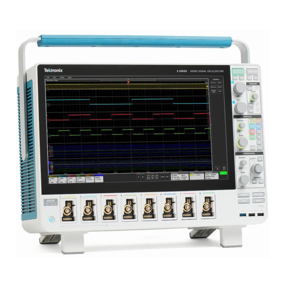
See the product Help file for more detailed information. Key features Welcome to the 5 Series Mixed Signal Oscilloscope. The 5 Series MSO Oscilloscopes (MSO54, MSO56, and MSO58) are 4-, 6-, ™ and 8-channel oscilloscopes with the world's first FlexChannel -based inputs, enabling you to efficiently and cost-effectively perform mixed signal debugging on virtually any design. - Page 14 Installing the instrument in a RM5MSO Rack Mount Kit Instructions (Tektronix part number 071-3523-xx; available at rack www.tektronix.com/downloads) Using the TLP058 Logic Probe TLP058 FlexChannel Logic Probe Instructions (Tektronix part number 071-3515-xx; available at www.tektronix.com/downloads) viii MSO54, MSO56, MSO58 Installation and Safety Manual...
-
Page 15: Installing Your Instrument
Installing your instrument Check shipped accessories Make sure that you received everything you ordered. If anything is missing, contact Tektronix Customer Support. In North America, call 1-800-833-9200. Worldwide, visit www.tek.com to find contacts in your area. Check the packing list that came with your instrument to verify that you have received all ordered items. Check that you received all standard accessories. -
Page 16: Operating Requirements
Installing your instrument Operating requirements Use the oscilloscope within the required operating temperature, power, altitude, and signal input voltage ranges to provide the most-accurate measurements and safe instrument operation. Environment requirements Characteristic Description Operating temperature 0 °C to +50 °C (+32 °F to +122 °F) For proper cooling, keep the sides and rear of the instrument clear of obstructions for 2 inches (51 mm). -
Page 17: Input Signal Requirements
Installing your instrument Input signal requirements Keep the input signals within allowed limits to ensure the most accurate measurements and prevent damage to the analog and digital probes or instrument. Make sure that input signals are within the following requirements. Input Description Analog input channels, 1 M Ω... -
Page 18: Powering The Oscilloscope
Installing your instrument Powering the oscilloscope Use this procedure to connect the oscilloscope to line power and power on and off the oscilloscope. Always connect the oscilloscope to AC power using the power cord that shipped with the instrument. Prerequisite: Use the AC power cord that shipped with your oscilloscope. Connect the supplied power cord to the oscilloscope power connector. -
Page 19: Check That Oscilloscope Passes Power-On Self Tests
If the power-on self test shows Failed: Power cycle the oscilloscope. Tap Utility > Self Test. If the power-on self test still shows Failed, contact Tektronix Customer Support. Connecting Probes Probes and cables connect the oscilloscope to your device under test (DUT). Use a probe that best matches your signal measurement needs. -
Page 20: Rackmount Information
RM5 Rackmount Kit (Option RM5). Purchase or obtain the rackmount kit. Follow the instructions that came with the rackmount kit (RM5 Rackmount Kit Instructions, Tektronix part number 071-3523- xx). Make sure to allow adequate clearance on the sides and rear for air ventilation, and on the back for any cables you attach to the rear panel. -
Page 21: Getting Acquainted With Your Instrument
The following content provides a high-level description of the instrument controls and user interface. Refer to the 5 Series Mixed Signal Oscilloscope MSO54, MSO56, MSO58 Help on the instrument for detailed information on using the controls and user interface to display waveforms and take measurements. - Page 22 Getting acquainted with your instrument ■ Run/Stop starts and stops waveform acquisition. The button color indicates the acquisition status (green = running and acquiring; red = stopped). When stopped, the oscilloscope shows waveforms from the last completed acquisition. The Run/Stop button on the screen also shows the acquisition status. ■...
- Page 23 Getting acquainted with your instrument Push a Multipurpose knob to enable the Fine mode for making smaller increment changes. Push the knob again to exit Fine mode. Trigger controls: Force forces a trigger event at a random point in the waveform and captures the acquisition. ■...
- Page 24 Getting acquainted with your instrument Vertical controls: ■ Position moves the selected waveform (Channel, Math, Reference, Bus) and its graticule up or down on the screen. The color of the Position knob indicates which waveform the knob is controlling. Push the knob to set the threshold level to 50% of the peak-to-peak amplitude range of the signal.
- Page 25 Getting acquainted with your instrument Horizontal controls: ■ Position moves the waveform and graticule side to side on the screen (changing the trigger point position in the waveform record). Push the knob to center the trigger event to the center graticule on the Waveform view. ■...
- Page 26 Getting acquainted with your instrument Miscellaneous controls: Touch Off turns touch screen capability off. The Touch Off button is lighted when the touch screen is turned off. ■ ■ User is a one-push save operation that uses the current menu bar File > Save As settings to save screen shots (including open menus and dialog boxes), waveform files, instrument settings, and so on, as follows: ■...
- Page 27 Getting acquainted with your instrument USB Host ports (USB 3.0 and 2.0): ■ USB ports are located at the lower right corner of the front panel, and on the rear panel. Connect USB flash drives to which you can save or recall data (such as instrument software updates, waveforms, settings, and screen captures), or connect peripheral devices such as a mouse or keyboard.
-
Page 28: Rear Panel Connections
Getting acquainted with your instrument Rear panel connections The rear panel connections supply power to the oscilloscope and provide connectors for network, USB devices, video, reference signals, and the AFG output. Power cord connector. Use only the power cord specified for this product and certified for the country of use. Ref In lets you connect a high-precision 10 MHz reference signal to the oscilloscope for more accurate measurements. -
Page 29: The User Interface Screen
Getting acquainted with your instrument The user interface screen The touch screen user interface contains waveforms and plots, measurement readouts, and touch-based controls to access all oscilloscope functions. The Menu bar provides menus for typical operations including: ■ Saving, loading, and accessing files ■... -
Page 30: The User Interface Elements
Getting acquainted with your instrument The Results Bar contains controls for displaying cursors, adding notes, plots, and result tables to the screen, and add measurements to the Results bar. The controls are: ■ The Cursors button displays on-screen cursors in the selected view. Touch and drag, or use the Multipurpose knobs, to move the cursors. - Page 31 Getting acquainted with your instrument The Waveform Record View is a graphical high-level view of the overall waveform record length, how much of the record is on the screen (shown in brackets), the location of key time events including the trigger event, and the current position of waveforms cursors.
- Page 32 Getting acquainted with your instrument When in Zoom mode, the Waveform Record View is replaced with the Zoom Overview. See The Zoom user interface on page 26. elements The Expansion Point icon on the waveform view shows the center point around which the waveform expands and compresses when changing horizontal settings.
-
Page 33: Badges
Getting acquainted with your instrument If you add more Channel or Waveform badges than can fit in the waveform badge area, use the scroll buttons at each end of the waveform badge area to let you scroll through all badges. 11. - Page 34 Getting acquainted with your instrument Channel badges are listed in the channel order. You cannot move Channel badges other than to drag them into the Trash Can icon to turn them off. Waveform badges (Math, Ref, Bus, Trend) are listed in the order created, and are grouped together by type. Deleting a Waveform badge does not change the order or names of the remaining badges.
- Page 35 Getting acquainted with your instrument The < (Previous) and > (Next) buttons center the waveform in the display at the position of the previous or next measurement point in the record (for measurements that take more than one measurement per acquisition). The Min' and Max' navigation buttons center the waveform in the display at the minimum or maximum value for that measurement in the current acquisition.
- Page 36 Getting acquainted with your instrument Some searches also provide Min and Max navigation buttons that open the Zoom mode and center the waveform in the display at the minimum or maximum value for that search event in the current acquisition. Search badges are listed in the order created.
- Page 37 Getting acquainted with your instrument Double-tap a System badge to open its configuration menu. The Horizontal badge also has Scale buttons, shown by single-tapping the badge. Use the Horizontal Scale buttons to increase or decrease the horizontal time setting. Common badge actions Action Result Example...
-
Page 38: Configuration Menus
Getting acquainted with your instrument Badge selection status The appearance of a badge indicates its selection status (selected or unselected), or if a measurement needs to be deleted to close a channel or waveform badge. Badge type Selected Unselected Turned off or in use Channel or Waveform Measurement... - Page 39 Getting acquainted with your instrument Selections or values that you enter take effect immediately. Menu contents are dynamic, and can change depending on your selections. Related settings are grouped into 'panels.' Tap the panel name to show those settings. Changes to panel settings can change the values and/or fields shown in that panel and other panels.
-
Page 40: The Zoom User Interface Elements
Getting acquainted with your instrument To open Help content for a configuration menu, tap the question mark Help icon in the upper right corner of the menu. The Zoom user interface elements Use the zoom tools to magnify waveforms to view signal details. The Zoom Overview shows the entire waveform record. -
Page 41: Using The Touch Screen Interface For Common Tasks
Getting acquainted with your instrument Using the touch screen interface for common tasks Use standard touch screen actions, similar to those found on smart phones and tablets, to interact with most screen objects. You can also use a mouse to interact with the UI. The equivalent mouse operation is shown for each touch operation. The oscilloscope has a user interface tutorial. - Page 42 Getting acquainted with your instrument Task Touchscreen UI action Mouse action Change horizontal or vertical settings Tap a badge and use the Scale buttons. Left-click a channel, waveform, or directly on a waveform. Pinch or expand two fingertips on the Horizontal badge and click on the Scale Vertical changes only apply to the waveform view, move them together or...
-
Page 43: Configure The Instrument
Update oscilloscope firmware from USB drive Prerequisite: Determine the current version of firmware installed on the oscilloscope (Help > About) Open up a Web browser on a PC and go to www.tektronix.com/software. Enter MSO5 in the search field and click Search. -
Page 44: Run Signal Path Compensation (Spc)
Close the Calibration configuration dialog when SPC has completed. If the SPC fails, write down any error message text. Make sure that all probes and cables are disconnected and run the SPC again. If the SPC still fails, contact Tektronix Customer Support. Compensate the TPP0500B or TPP1000 probes Probe compensation adjusts the high frequency response of a probe for best waveform capture and measurement accuracy. - Page 45 Configure the instrument If the Probe Compensation Status field displays Fail, the attached probe has failed the probe compensation procedure. ■ Reconnect the probe and run probe compensation again. If there is no probe compensation status field shown in the panel, the oscilloscope cannot store compensation values for ■...
-
Page 46: Connect To A Network (Lan)
Configure the instrument 11. Repeat these steps for each supported passive probe that you want to compensate for this channel. 12. Repeat these steps to compensate supported probes on other channels of the oscilloscope. NOTE. For most accurate measurements, open the Probe Setup panel and verify the Probe Compensation Status is Pass whenever you attach a probe to a channel. -
Page 47: Operating Basics
Operating basics These procedures are an introduction to using the interface to do common tasks. See the Help information in the application for detailed information on menu and field settings. Add a channel waveform to the display Use this procedure to add a channel signal to the Waveform View. Connect signal(s) to the channel input(s). -
Page 48: Configure Channel Or Waveform Settings
Operating basics Configure channel or waveform settings Use the channel and waveform configuration menus to set parameters such as vertical scale and offset, coupling, bandwidth, probe settings, deskew values, external attenuation values, and other settings. Prerequisite: There is a channel or waveform badge in the Settings bar. Double-tap a Channel or Waveform badge to open a configuration menu for that item. -
Page 49: Quickly Display A Waveform (Autoset)
Operating basics Quickly display a waveform (Autoset) The Autoset function analyzes the signal characteristics and changes the instrument Horizontal, Vertical, and Trigger settings to automatically display a triggered waveform. You can then make further changes to trigger and horizontal settings to view the waveform point of interest. -
Page 50: How To Trigger On A Signal
NOTE. Triggering on buses other than Parallel requires purchasing and installing serial trigger and analysis options. See the Tektronix Web site for available serial trigger and analysis options. Select the other fields and panels to refine the trigger conditions. The menu fields and trigger graphic update as you make changes to the trigger settings. -
Page 51: Set The Acquisition Mode
Operating basics Tap the Help icon on the menu title for more information on these settings. Tap outside the menu to close the menu. Set the acquisition mode Use this procedure to set the method the instrument uses to acquire and display the signal. Double-tap the Acquisition badge on the Settings bar to open the Acquisition configuration menu. -
Page 52: Set Horizontal Parameters
Operating basics Tap the Help icon on the menu title for more information on these settings. Tap outside the menu to close the menu. Set Horizontal parameters Use this procedure to set the horizontal time base parameters such as mode, minimum sample rate, horizontal scale, delay, and trigger delay time (relative to the center of the waveform record. - Page 53 Operating basics Use the configuration menus to refine the waveform parameters. Displayed fields depend on the waveform and selections made in the menu. Selection changes take effect immediately. This example shows adding a Math waveform, using the Math Source fields to select Ch 1 and Ch 2 as the waveform sources, and set the math type to Basic math operation, and subtracting channel 2 from channel 1.
-
Page 54: Add A Measurement
Operating basics Add a measurement Use this procedure to select and add measurements. Acquire the channel(s) and/or waveform(s) on which you want to take measurements. NOTE. Waveforms do not need to be displayed to be used for measurements, as long as the channel or waveform badge is on the Settings bar and is acquiring the signal to measure. - Page 55 Operating basics Select from the configuration menu panels, such as Amplitude, Timing, and Jitter, to display measurements for those categories. Select a measurement and tap Add (or double-tap the measurement) to add the measurement to the Results bar. The measurement badge is added immediately. Select and add other measurements for the current source.
-
Page 56: Configure A Measurement
Operating basics Tap outside the Add Measurements menu to close the menu. To further adjust a measurement's settings, double-tap a measurement badge to open a configuration menu for that measurement. See on page 42. Configure a measurement 10. Tap the Help icon on the menu title for more information on settings. Configure a measurement Use this procedure to add statistical readouts to the measurement badge, display plots for the measurement, and refine measurement parameters (configuration, global versus local scope of settings, gating, filtering, and so on). -
Page 57: Add A Plot Of A Measurement
Operating basics Use the available fields to refine the measurement conditions. Displayed fields depend on the measurement. Selection changes take effect immediately. Selection changes can also change fields in other panels. Tap the Help button on the menu title for more information on this menu's settings. Tap outside the menu to close the menu. - Page 58 Operating basics The following shows adding a Histogram plot. You can add more than one plot to measurements (to different measurements or the same measurement). For example, you can add two histogram plots for the same measurement, set one to display the X-Axis with a Logarithmic scale, and the other plot to display the X-Axis with a Linear scale.
-
Page 59: Add A Search
Operating basics Add a Search Use this procedure to set search criteria and mark a waveform where those events occur. You can search on analog and digital signals, math waveforms, and reference waveforms. You can add searches to different waveforms and multiple searches to the same waveform. Prerequisite: Display the channel or waveform signal on which to search. -
Page 60: Delete A Measurement Or Search Badge
Operating basics NOTE. Navigation buttons are only functional when the oscilloscope acquisition mode is set to Stop. This opens the Zoom mode and moves the waveform to the previous or next event mark on the waveform. If available for a search, tap the Min or Max button to center the waveform in the display at the minimum or maximum value of the search events in the waveform record. -
Page 61: Change Waveform View Settings
Operating basics Change waveform view settings Use this procedure to change the waveform display mode (Stacked or Overlay), waveform trace interpolation algorithm, waveform persistence, style and intensity, and graticule style and intensity. Double-tap on an open graticule area to open the Waveform View configuration menu. Tap the buttons in the Display Mode to toggle between Overlay and Stacked modes. - Page 62 Operating basics Use Multipurpose Knobs A and B to move the cursors, or touch and drag a cursor. Cursors show readouts that show position and difference measurements between the cursors. To move the cursors to a different channel or waveform, just tap in that waveform graticule. To further configure cursors, double-tap on either cursor line or the cursor readouts to open the Cursors configuration menu.
-
Page 63: Remote Access From A Web Browser
Operating basics The cursors are moved to the specified waveforms. Tap the Help icon on the menu title for more information on the menu settings. To stop showing cursors, push the front panel Cursor button, press and hold to open the right-click menu and turn cursors off, or open the Cursors configuration menu and set Display to Off. -
Page 64: Connect The Oscilloscope To A Pc Using A Usb Cable
Operating basics Connect the oscilloscope to a PC using a USB cable Use a USB cable to connect the oscilloscope directly to a PC for remote instrument control. On the oscilloscope, select Utility > I/O from the menu bar. Tap USB Device Port Settings. Confirm that the USB Device Port control is On (default setting). -
Page 65: Cleaning The Instrument
Cleaning the instrument Cleaning Use a dry, soft cotton cloth to clean the outside of the unit. Do not use any liquid cleaning agents or chemicals that could damage the touch screen, case, controls, screen, markings or labels, or possibly infiltrate the case. MSO54, MSO56, MSO58 Installation and Safety Manual... - Page 66 Cleaning the instrument MSO54, MSO56, MSO58 Installation and Safety Manual...
-
Page 67: Emc, Safety And Environmental Compliance
■ EN 61000-3-2. AC power line harmonic emissions EN 61000-3-3. Voltage changes, fluctuations, and flicker European contact. Tektronix, Inc. PO Box 500, MS 19‐045 Beaverton, OR 97077, USA www.tek.com Australia / New Zealand EMC Complies with the EMC provision of the Radiocommunications Act per the following standard, in accordance with ACMA: EN 61326-1 and EN 61326-2-1. -
Page 68: Safety Compliance
EMC, safety and environmental compliance Safety compliance This section lists the safety standards with which the product complies and other safety compliance information. EU low voltage directive Compliance was demonstrated to the following specification as listed in the Official Journal of the European Union: Low Voltage Directive 2014/35/EU. -
Page 69: Environmental Compliance
Directives 2012/19/EU and 2006/66/EC on waste electrical and electronic equipment (WEEE) and batteries. For information about recycling options, check the Tektronix Web site (www.tek.com/productrecycling). Perchlorate materials. This product contains one or more type CR lithium batteries. According to the state of California, CR lithium batteries are classified as perchlorate materials and require special handling. - Page 70 EMC, safety and environmental compliance MSO54, MSO56, MSO58 Installation and Safety Manual...
- Page 71 Index common touchscreen UI tasks, 27 compensate TPP0500, TPP1000 probes, 30 A knob, 7 Compliance information, 53 Acquisition controls, 7 configuration menus, 24 acquisition menu, open, 37 configure a measurement, 42 add a channel to the display, 33 connect lock cable, 3 add a measurement badge, 40 connect to a network, 32 add a measurement plot, 43...
- Page 72 Index front panel handles, analog and digital, 16 Acquisition, 7 High Res button, 7 Autoset button, 7 Horizontal controls, 7 Bus button (front panel), 7 horizontal menu, open, 38 Channel buttons (front panel), 7 how to Clear button, 7 connect probes, 5 Cursors button, 7 add a measurement, 40 Default Setup, 7...
- Page 73 Index use Autoset, 35 navigation buttons, badges, 19–24 use mouse with the UI, 27 network, connect to, 32 How to Note button, 15 change display mode (stacked, Overlay), 47 open acquisition menu, 37 inactive channel buttons, 16 open horizontal menu, 38 input signal level requirements, 3 operating intensity, graticule, 47...
- Page 74 Index rear panel security cable lock, 14 AFG Out, 14 AUX Out, 14 clock format (12/24 hr), 29 cable lock, 14 Date/Time badge display on, off, 29 Display Port video output, 14 GPIB talk/listen address, 50 DVI video output, 14 probe deskew, 34 Ethernet port (RJ-45), 14 probe parameters, 34...
- Page 75 Index waveform badge, 19–24 Waveform View, 15 Vertical controls, 7 VGA video output (rear panel), 14 video outputs (rear panel), 14 Zoom box, 26 Zoom button (front panel), 7 waveform zoom icon, 16 expansion point, 16 Zoom overview, 26 intensity, 47 Zoom title bar, 26 persistence, 47 Zoom/Pan knobs (horizontal), 7...
- Page 76 Index MSO54, MSO56, MSO58 Installation and Safety Manual...
- Page 77 5 シリーズ・ミックスド・シグナル・オシロスコープ MSO54 型、MSO56 型、MSO58 型 インストールおよび安全性に関するマニュアル *P071351400* 071-3514-00...
- Page 79 5 シリーズ・ミックスド・シグナル・オシロスコープ MSO54 型、MSO56 型、MSO58 型 インストールおよび安全性に関するマニュアル 5 シリーズ MSO 製品ファームウェア V1.0 以降をサポート www.tek.com 071-3514-00...
- Page 80 © Copyright Tektronix.All rights reserved.使用許諾ソフトウェア製品は、Tektronix またはその子会社や供給者が所有するもの で、米国著作権法および国際条約の規定によって保護されています。Tektronix 製品は、登録済および出願中の米国その 他の国の特許等により保護されています。本書の内容は、既に発行されている他の資料の内容に代わるものです。また、 本製品の仕様および価格は、予告なく変更させていただく場合がございますので、予めご了承ください。 TEKTRONIX および TEK は Tektronix, Inc. の登録商標です。 FlexChannel および TekSecure は、Tektronix, Inc.の商標です。 TekVPI、FastAcq、e*Scope は Tektronix, Inc.の登録商標です。 Tektronix 連絡先 Tektronix, Inc. 14150 SW Karl Braun Drive P.O. Box 500 Beaverton, OR 97077 製品情報、代理店、サービス、およびテクニカル・サポート:...
- Page 81 保証 当社では、本製品において、認定された当社代理店による出荷の日から 3 年間、材料およびその仕上がりについて欠陥 がないことを保証します。本保証期間中、かかる製品に欠陥があることが判明した場合、当社は、当社の判断にて、部品 および作業の費用を請求せずに当該欠陥製品を修理するか、または当該欠陥製品と交換に代替品を提供します。当社 が保証遂行のために使用する部品、モジュール、および代替品は、新品の場合もあれば、新品同様の性能を持つ再生品 の場合もあります。交換後、当社が引き取った部品、モジュール、および製品はすべて当社の所有物となります。 お客様が本保証に基づくサービスを受けるには、適用保証期間が満了する前に、当該欠陥について当社に通知し、サー ビス実施に関する適切な手配を行う必要があります。お客様には、当該欠陥製品を梱包していただき、送料元払いにて当 社指定のサービス受付センターに送付していただきます。製品をお客様に返送する際、返送先が当社サービス受付セン ターの所在国と同一国内にある場合には、当社がその返送費用を負担するものとします。上記以外の場所に返送される 製品については、すべての発送費用、関税、税、およびその他の費用を支払う責任はお客様が負うものとします。 製品の不適切な使用または整備点検の不足によって生じた欠陥、障害、または損傷は、本保証の対象外です。当社は、 a)当社担当者以外の者による本製品の設置、修理または整備の実施から生じた損傷に対する修理、b)不適切な使用ま たは互換性のない機器への接続から生じた損傷に対する修理、c)当社製以外のサプライ用品の使用により生じた損傷ま たは動作不良に対する修理。d)本製品が改造または他の製品と統合された場合において、かかる改造または統合の影 響により当該本製品の整備の時間または難易度が増加した場合の当該本製品に対する整備については、本保証に基づ くサービスを提供する義務を負わないものとします。 本保証は、明示であるか黙示であるかを問わず他のあらゆる保証の代わりに、本製品に関して当社がお客様に対して提 供するものです。テクトロニクスおよびその販売店は、商品性または特定目的に対する適合性についての一切の黙示保 証を否認します。不具合のある製品を修理または交換するという当社の責任行為は、本保証の義務違反に対してお客様 に提供される唯一の救済手段です。当社および当社代理店は、間接的、限定的、偶発的、または派生的な損害について は、かかる損害の可能性を事前に通知されていたか否かにかかわらず、一切責任を負わないものとします。 [W4 – 15AUG04]...
- Page 83 目次 ......................... 安全性に関する重要な情報 ........................安全にご使用いただくために ...................... 安全に保守点検していただくために ..........................本マニュアル内の用語 ............................ 本機に関する用語 ............................本製品の記号: ................................まえがき ..............................主な特長 ..........................関連するマニュアル 本機の設置 ..........................同梱アクセサリの確認 ..........................ハンドルの安全な回転 ..............................動作要件 ............................. 入力信号要件 ........................ オシロスコープの固定(ロック) ......................... オシロスコープへの電源投入 ............パワーオン・セルフ・テストでのオシロスコープの合格の確認 ............................プローブの接続 ............................. ラックマウント情報 機器の詳細 ....................前面パネル・コントロールおよびコネクタ...
- Page 84 目次 ........................信号経路補正(SPC)の実行 TPP0500B 型プローブまたは TPP1000 型プローブの補正 ....................................ネットワークヘの接続(LAN) 基本操作 .................... ディスプレイへのチャンネル波形の追加 ....................チャンネル設定または波形設定の構成 ......................波形の高速表示(オートセット) ........................信号にトリガをかける方法 ......................... アクイジション・モードの設定 ........................水平軸パラメータの設定 ................ 演算波形、リファレンス波形またはバス波形の追加 ............................... 測定の追加 ............................... 測定の構成 ..........................測定のプロットの追加 ............................... 検索の追加 ....................測定バッジまたは検索バッジの削除 ........................... 波形ビュー設定の変更 ........................カーソルの表示および構成 Web ブラウザからのリモート・アクセス ....................
-
Page 85: 安全性に関する重要な情報
安全性に関する重要な情報 安全性に関する情報として、機器の安全な操作と、機器の安全な動作状態の維持に役立つ警告事項と注意事項 が掲載されています。 このマニュアルには、操作を行うユーザの安全を確保し、製品を安全な状態に保つために順守しなければならな い情報および警告が記載されています。 安全にご使用いただくために 」に続く「Service safety summary」を参照して、事故防止に 本機の点検にあたっては「 つとめてください。 安全にご使用いただくために 製品は指定された方法でのみご使用ください。人体への損傷を避け、本製品や本製品に接続されている製品の 破損を防止するために、安全性に関する次の注意事項をよくお読みください。すべての指示事項を注意深くお読 みください。必要なときに参照できるように、説明書を安全な場所に保管しておいてください。 該当する地域および国の安全基準に従ってご使用ください。 本製品を正しく安全にご使用になるには、このマニュアルに記載された注意事項に従うだけでなく、一般に認めら れている安全対策を徹底しておく必要があります。 本製品は訓練を受けた専門知識のあるユーザによる使用を想定しています。 製品のカバーを取り外して修理や保守、または調整を実施できるのは、あらゆる危険性を認識した専門的知識の ある適格者のみに限定する必要があります。 使用前に、既知の情報源と十分に照らし合わせて、製品が正しく動作していることを常にチェックしてください。 本製品は危険電圧の検出用にはご利用になれません。 危険な通電導体が露出している部分では、感電やアーク・フラッシュによってけがをするおそれがありますので、 保護具を使用してください。 本機を大きなシステムの下で使用する場合、そのシステムを構成する他のパーツにアクセスしなければならない 場合があります。他のシステムの操作に関する警告や注意事項については、その製品コンポーネントのマニュア ルにある安全に関するセクションをお読みください。 本機をシステムの一部として使用する場合、そのシステムの安全性についてはシステムの構築者が責任を負うも のとします。 火災や人体への損傷を避けるには 適切な電源コードを使用してください: 電源コードは本機に適した仕様で、使用国の基準を満たすもののみを使 用してください。他の製品の電源コードは使用しないでください。 本製品を接地してください: 本製品の電源コードには接地用のグランド線が付いています。感電を避けるため、グ ランド線をアースに接続する必要があります。本製品の入出力端子に接続する前に、製品が正しく接地されてい ることを確認してください。電源コードのグランド接続を無効にしないでください。 電源の切断: 本製品は、電源コードを引き抜いて電源ソースから切断します。スイッチの位置については、使用 説明書を参照してください。電源コードの取り扱いが困難な場所には設置しないでください。必要に応じてすぐに... - Page 86 安全性に関する重要な情報 すべての端子の定格に従ってください: 発火や感電の危険を避けるために、本製品のすべての定格とマーキン グに従ってください。本製品に電源を接続する前に、定格の詳細について、製品マニュアルを参照してください。 測定カテゴリ(CAT)の定格および電圧と電流の定格については、製品、プローブ、またはアクセサリのうちで最も 低い定格を超えないように使用してください。1:1 のテスト・リードを使用するときは、プローブ・チップの電圧が直 接製品に伝送されるため注意が必要です。 コモン端子を含むどの端子にも、その端子の最大定格を超える電位をかけないでください。 コモン端子の定格電圧を超えてコモン端子をフローティングさせないでください。 カバーを外した状態で動作させないでください: カバーやパネルを外した状態やケースを開いたまま動作させない でください。危険性の高い電圧に接触してしまう可能性があります。 露出した回路への接触は避けてください: 電源が投入されているときに、露出した接続部分やコンポーネントに触 れないでください。 故障の疑いがあるときは使用しないでください: 本製品に故障の疑いがある場合には、資格のあるサービス担当 者に検査を依頼してください。 製品が故障している場合には、使用を停止してください。製品が故障している場合や正常に動作していない場合 には、製品を使用しないでください。安全上の問題が疑われる場合には、電源を切って電源コードを取り外してく ださい。誤って使用されることがないように、問題のある製品を区別できるようにしておいてください。 使用前に、電圧プローブ、テスト・リード、およびアクセサリに機械的損傷がないかを検査し、故障している場合に は交換してください。金属部が露出していたり、摩耗インジケータが見えているなど、損傷が見られるプローブま たはテスト・リードは使用しないでください。 使用する前に、製品の外観に変化がないかよく注意してください。ひび割れや欠落した部品がないことを確認して ください。 指定された交換部品のみを使用するようにしてください。 適切なヒューズを使用してください: 本製品用に指定されたヒューズ・タイプおよび定格のみを使用してください。 保護メガネを着用してください: 強力な光線またはレーザー照射にさらされる危険性がある場合は、保護メガネを 着用してください。 湿気の多いところでは動作させないでください: 機器を寒い場所から暖かい場所に移動する際には、結露にご注 意ください。 爆発性のガスがある場所では使用しないでください: 製品の表面を清潔で乾燥した状態に保ってください: 製品の清掃を開始する前に、入力信号を取り外してくださ い。 適切に通気してください:...
- Page 87 安全性に関する重要な情報 製品を持ち上げたり運んだりする作業は慎重に行ってください。本製品には持ち運び用のハンドルが取り付けら れています。 本製品には指定された当社のラック取り付け金具のみを使用してください。 プローブとテスト・リード プローブやテスト・リードを接続する前に、電源コードを使用して本機を適切に接地された AC コンセントに接続し てください。 感電を避けるために、指ガードの先に指を出さないように注意してください。 使用しないプローブ、テスト・リード、アクセサリはすべて取り外してください。 測定に使用するプローブ、テスト・リード、アダプタは、測定カテゴリ(CAT)、電圧、温度、高度、アンペア数の定格 が適切なもののみを使用してください。 高電圧に注意: 使用するプローブの電圧定格について理解し、その定格を超えないようにしてください。特に次の 2 つの定格についてはよく理解しておく必要があります。 ■ プローブ・チップとプローブの基準リード間の最大測定電圧 ■ プローブの基準リードとアース間の最大フローティング電圧 上記の 2 つの電圧定格はプローブと用途によって異なります。詳細については、プローブのマニュアルの仕様関 連セクションを参照してください。 警告: 感電を防止するために、オシロスコープの入力 BNC コネクタ、プローブ・チップ、またはプローブ基準リード の最大測定電圧や最大フローティング電圧を超えないように注意してください。 接続と切断は正しく行ってください: プローブ出力を測定器に接続してから、プローブを被測定回路に接続してくだ さい。被測定回路にプローブの基準リードを接続してから、プローブ入力を接続してください。プローブ入力とプロ ーブの基準リードを被測定回路から切断した後で、プローブを測定器から切断してください。 着脱は正しく行ってください: 被測定回路は、電流プローブを着脱する前に電源を切断してください。 プローブの基準リードはアースにのみ接続してください。 電流プローブを、その定格電圧を超える電圧の電線に接続しないでください。 プローブとアクセサリを検査してください: 使用前には必ずプローブとアクセサリに損傷がないことを確認してくだ さい(プローブ本体、アクセサリ、ケーブル被覆などの断線、裂け目、欠陥)。損傷がある場合には使用しないでく...
-
Page 88: 安全に保守点検していただくために
安全性に関する重要な情報 安全に保守点検していただくために 「安全に保守点検していただくために」のセクションには、製品の保守点検を安全に行うために必要な詳細な情報 が記載されています。資格のあるサービス担当者以外は、保守点検手順を実行しないでください。保守点検を行 う前には、この「安全に保守点検していただくために」と「安全にご使用いただくために」をお読みください。 感電を避けるため、: 露出した接続部には触れないでください。 保守点検は単独で行わないでください。: 応急処置と救急蘇生ができる人の介在がない限り、本製品の内部点 検や調整を行わないでください。 電源を切断してください。: 保守点検の際にカバーやパネルを外したり、ケースを開く前に、感電を避けるため、製 品の電源を切り、電源コードを電源コンセントから抜いてください。 電源オン時の保守点検には十分注意してください。: 本製品には、危険な電圧や電流が存在している可能性が あります。保護パネルの取り外し、はんだ付け、コンポーネントの交換をする前に、電源の切断、バッテリの取り 外し(可能な場合)、テスト・リードの切断を行ってください。 修理後の安全確認。: 修理を行った後には、常にグランド導通と電源の絶縁耐力を再チェックしてください。 本マニュアル内の用語 本マニュアルでは以下の用語を使用しています。 警告: 人体や生命に危害をおよぼすおそれのある状態や行為を示します。 注意: 本機やその他の接続機器に損害を与えるおそれのある状態や行為を示します。 本機に関する用語 本機では次の用語を使用します。 ■ 危険: ただちに人体や生命に危険をおよぼす可能性があることを示します。 ■ 警告: 人体や生命に危険をおよぼす可能性があることを示します。 ■ 注意: 本製品を含む周辺機器に損傷を与える可能性があることを示します。 MSO54 型、MSO56 型、MSO58 型のインストールおよび安全性に関するマニュアル... -
Page 89: 本製品の記号
安全性に関する重要な情報 本製品の記号: 製品にこの記号が表記されているときは、マニュアルを参照して、想定される危険性とそれらを回避す るために必要な行動について確認してください。(マニュアルでは、この記号はユーザに定格を示すた めに使用される場合があります)。 本製品では、次の記号を使用します。 MSO54 型、MSO56 型、MSO58 型のインストールおよび安全性に関するマニュアル... - Page 90 安全性に関する重要な情報 viii MSO54 型、MSO56 型、MSO58 型のインストールおよび安全性に関するマニュアル...
-
Page 91: まえがき
まえがき 本マニュアルには、製品の安全とコンプライアンス、オシロスコープの接続方法と電源供給方法、機器の機能と制 御と基本操作の概要が記載されています。詳細については、製品の Help(ヘルプ)ファイルを参照してください。 主な特長 5 シリーズ・ミックスド・シグナル・オシロスコープをご紹介します。5 シリーズ MSO オシロスコープ(MSO54 型、 MSO56 型、MSO58)は、4 チャンネル式、6 チャンネル式、8 チャンネル式のオシロスコープで、入力は世界初の ™ FlexChannel をベースとしており、実質的にあらゆる設計において効率的かつ費用効果の高いミックスド・シグナ ル・デバッキングを実現します。 ■ 帯域幅 350MHz~2GHz ■ FlexChannel 入力の 4 チャンネル式、6 チャンネル式、8 チャンネル式 ■ 各 FlexChannel 入力はあらゆる組み合わせにおいて 1 アナログ・チャンネルまたは 8 デジタル・チャンネルに 対応 ® ■... - Page 92 シリーズのミックスド・シグナル・オシロスコープ MSO54 型、 MSO56 型、 MSO58 型の 機器の機能の使用方法 ヘルプ (当社部品番号 077-1303-xx;機器の印刷可能バージョンのヘルプ; www.tektronix.com/downloads より入手可能) 機器を遠隔で操作する方 シリーズのミックスド・シグナル・オシロスコープ MSO54 型、 MSO56 型、 MSO58 型の 法 プログラマー・マニュアル (当社部品番号 077-1305-xx;www.tektronix.com/downloads よ り入手可能) シリーズのミックスド・シグナル・オシロスコープ MSO54 型、 MSO56 型、 MSO58 型の 機器の仕様および機器の 仕様への適合性を確認す 仕様および性能確認用テクニカル・リファレンス (当社部品番号 077-1306-xx; る手順...
-
Page 93: 同梱アクセサリの確認
本機の設置 同梱アクセサリの確認 注文したものがすべてお手元に届いたことを確認してください。足りないものがある場合には、当社カスタマ・サポ ートにお問い合わせください。北米:1-800-833-9200 までお電話ください。世界の他の地域では、www.tek.com にアク セスし、お近くの代理店をお探しください。 本機の付属品一覧を見て、注文品がすべて届いているか確認してください。スタンダード・アクセサリがすべて届 いているか確認してください。 項目 数量 当社部品番号 071-3514-xx シリーズミックスド・シグナル・オシロスコープ( MSO54 型、 MSO56 型、 MSO58 型)のインストールおよび安全性に関するマニュアル TPP0500B 型受動電圧プロ―ブ(帯域幅 500MHz)350MHz 型と 1 チャンネルにつき 1 TPP0500B 型 500MHz 型の同梱品 つ TPP1000 TPP1000 型受動電圧プローブ(帯域幅 1GHz)1GHz 型と 2GHz 型の 1 チャンネルにつき 1 同梱品... -
Page 94: 動作要件
本機の設置 動作要件 高い測定精度と安全な機器動作を確保するために、動作温度、電力、高度、信号入力電圧の各必須範囲内でこ のオシロスコープを使用してください。 環境要件 特性 説明 0℃~+ 50℃(+ 32°F~+ 122°F) 動作温度 正しく冷却するために、本機の側面と背面から 2 インチ(51mm)の範囲に は障害物を置かないでください。 + 40℃(+ 104°F)以下での相対湿度(RH)5%~90% 動作湿度 40℃~50℃(+ 104°F~+ 122°F)での相対湿度(RH)5%~55%、結露しない こと。 3,000m(9,842 フィート)以下 動作高度 電力要件 特性 説明 100V~240V 電源電圧 、±10%、単相 AC RMS 50/60Hz、100V~240V(90V~264V) 電源周波数 400Hz、115V(103V~127V) 全機種共通:最大 400W 消費電力... -
Page 95: 入力信号要件
本機の設置 入力信号要件 入力信号を許容制限内に収めることで、正確な測定を確保し、アナログとデジタルのプローブまたは機器への損 傷を防ぎます。 入力信号が以下の要件の範囲内にあることを確認します。 入力 説明 300V アナログ入力チャンネル、1MΩ 設定、BNC で最大入力 測定カテゴリ II 電圧 アナログ入力チャンネル、50Ω 設定、BNC で最大入力 電圧 デジタル入力チャンネル、デジタル入力で最大入力電 プローブ定格の観察 TLP058;±42V 圧レンジ Ref In:BNC で最大入力電圧(後部パネル) オシロスコープの固定(ロック) プロパティの損失を防ぐために、オシロスコープをテスト・ベンチや設備ラックにロックします。 標準的なラップトップ用セキュリティ・ロックをオシロスコープの後部パネルに取り付けて、オシロスコープをワーク ベンチやラック、その他の場所に固定します。 MSO54 型、MSO56 型、MSO58 型のインストールおよび安全性に関するマニュアル... -
Page 96: オシロスコープへの電源投入
本機の設置 オシロスコープへの電源投入 この手順では、オシロスコープをライン電源に接続し、オシロスコープへの電源の投入と遮断を行います。オシロ スコープを AC 電源に接続する時には必ず、本機に同梱されている電源コードを使用してください。 前提条件:オシロスコープに同梱されている AC 電源コードを使用してください。 付属の電源コードをオシロスコープの電源コネクタに接続します。 電源コードを適切な AC 電源に接続します。 AC 電源コードが導通状態の電源回路に接続されると、電力が電源供給部とその他の基盤に供給され、本機 が Standby(スタンバイ)モードに入ります。 本機の電源をオンまたはオフにするには、前面パネルの電源ボタンを押します。 電源ボタンには本機の電源ステータスが表示されます。 無灯 – AC 電力が投入されていない 黄色 – Standby(スタンバイ)モード 青色 – 電源オン 本機の電源を完全に切るには、電源コードを抜きます。 電源コードを含む本機を移動する場合には、後部パネルの上端の電源コード支持具を引き出し、電源コード を支持具に巻き付けてください。 MSO54 型、MSO56 型、MSO58 型のインストールおよび安全性に関するマニュアル... -
Page 97: パワーオン・セルフ・テストでのオシロスコープの合格の確認
本機の設置 パワーオン・セルフ・テストでのオシロスコープの合格の確認 パワーオン・セルフ・テストでは、オシロスコープの全機種が起動後に正常に作動するかを確認します。 オシロスコープの電源を入れて、オシロスコープのスクリーンに表示が出るまで待ちます。 上端のメニュー・バーで Utility(ユーティリティ)> Self Test(セルフ・テスト)を選択し、Self Test(セルフ・テスト) のコンフィグレーション・メニューを開きます。 パワーオン・セルフ・テストに Pass(合格)しているかを確認します。 パワーオン・セルフ・テストの結果が Failed(不合格)と表示されている場合: オシロスコープの電源を入れ直します。 Utility(ユーティリティ)> Self Test(セルフ・テスト)をタップします。それでもパワーオン・セルフ・テストの結 果が Failed(不合格)と表示される場合には、当社カスタマ・サポートに問い合わせてください。 プローブの接続 プローブとケーブルを使ってオシロスコープを被測定装置(DUT)に接続します。プローブは信号測定のニーズに 最適なものを使用してください。 ® ® 、TPP0500、TPP1000、TekVPI+ 、TekVPI 、またはサポートされているその他の当社アナログ・プローブを FlexChannel コネクタに挿入して接続します。プローブは完全に挿入されると、プローブのベース・ラッチがカチッと 音を立ててロックされます。 TekVPI プローブについては、このプローブのチャンネル入力パラメータ(帯域幅、減衰比、ターミネーションなど) が自動で設定されます。プローブに Menu(メニュー)ボタンがある場合、そのボタンを押してスクリーン上のコンフ ィグレーション・メニューを開きます。アクティブなプローブの取扱説明書に従ってパラメータ(自動ゼロ、デガウス など)を設定します。 TLP058 FlexChannel ロジック・プローブの接続方法 ロック・レバーをアンロック位置に移動させ、ロック・レバーが中央に戻るまで待ちます。... -
Page 98: ラックマウント情報
本機の設置 ロック・レバーをロック位置に移動させます。ステータス・ライトが緑色に点灯します。 TLP058 プローブを取り外すには、ロック・レバーをアンロック位置に移動させたままプローブを引き抜きます。 プローブを取り外している時にリボン・ケーブルを引っ張らないでください。 BNC のプローブまたはケーブルをチャンネル BNC 差し込みコネクタに挿入して接続し、ロック・メカニズムをロック されるまで時計回りに回します。 プローブを接続しても、そのチャンネルは自動的に表示されたり有効化されたりすることはありません。そのチャ ンネルをオンにするには Inactive Channel(無効チャンネル)ボタンをタップします。プローブまたはケーブルの設定 (帯域幅、減衰、ターミネーションなど)の確認や変更を行うには、Channel(チャンネル)バッジをダブルタップしてそ のコンフィグレーション・メニューを開きます。 ラックマウント情報 オプションの RM5 ラックマウント・キットを使用すると、標準的な設備ラックにオシロスコープを取り付けることがで きます。ラックマウントには、取り付けスペースとして 7 つのラック・ユニットが必要です。 RM5 ラックマウント・キット(オプション RM5) ラックマウント・キットを購入または入手します。 ラックマウント・キット取扱説明書 、当社部品番号 071-3523-xx)に従 ラックマウント・キットの取扱説明書(RM5 います。 通気のために両サイドと後部に適度なスペースを、後部パネルにケーブルを取り付けるので背面にも適度な スペースを確保できることを確認してください。 MSO54 型、MSO56 型、MSO58 型のインストールおよび安全性に関するマニュアル... -
Page 99: 前面パネル・コントロールおよびコネクタ
機器の詳細 次は、本機のコントロールとユーザ・インタフェースに関する高レベルの説明です。 コントロールとユーザ・インタフェースを使用した波形の表示および測定の実施に関する詳細については、本機の 「 5 シリーズのミックスド・シグナル・オシロスコープ MSO54 型、 MSO56 型、 MSO58 型のヘルプ」 を参照してくださ い。 前面パネル・コントロールおよびコネクタ 前面パネルのコントロールを使うと、垂直軸、水平軸、トリガ、カーソル、ズームなどといった主要機器設定に直接 アクセスできます。これらのコネクタは、プローブまたはケーブルで信号を入力した位置か、または USB デバイス を挿入した位置にあります。 アクイジションと カーソルのコントロール: ■ Run/Stop(実行/停止)は、波形の取り込み(アクイジション)の開始と停止を行う機能です。ボタンの色 はアクイジションのステータスを示します(緑色=アクイジション実行中、赤色=停止)。停止時、オシロス MSO54 型、MSO56 型、MSO58 型のインストールおよび安全性に関するマニュアル... - Page 100 機器の詳細 コープには最後に完了したアクイジションの波形が表示されます。スクリーン上の Run/Stop(実行/停止) ボタンにもアクイジション・ステータスが表示されます。 ■ Cursors(カーソル)ボタンはスクリーン・カーソルをオンまたはオフにする機能です。カーソルを移動させる には汎用ノブを使用します。カーソルのタイプと機能を設定するには、カーソルのリードアウトをダブルタ ップするか、またはカーソル・バー(ライン)上をダブルタップして、コンフィグレーション・メニューを開きま カーソルの表示および構成 (52 ページ)」を参照してください。 す。「 ■ Fast Acq ™ は Fast acquisition(高速アクイジション)モードの有効化と無効化を行う機能です。FastAcq で は、波形のアクイジションが行われる間のデッド・タイムが短縮されるため、グリッチやラント・パルスなど の過渡的イベントであっても、取り込み、表示することができます。捉えるのが困難な信号異常の検出に 役立ちます。また、Fast acquisition(高速アクイジション)モードでは、発生頻度に応じた輝度で波形現象を 表示できます。 ■ Single/Seq(単発/連続)を使うと、単発の波形アクイジションや、指定した回数のアクイジションを実行で きます(Acquisition(アクイジション)のコンフィグレーション・メニューで設定)。Single/Seq(単発/連続)を 押すと Run/Stop(実行/停止)モードがオフになり、単発のアクイジションが実行されます。ボタンの色は アクイジションのステータスを示します(緑色の高速点滅=単発アクイジション実行、緑色の点灯=トリ ガ・イベント待ち)。もう一度 Single/Seq(単発/連続)を押すと別の単発アクイジションが実行されます。 ■ High Res(ハイレゾ)は、現在のサンプル・レートに基づいて固有の有限インパルス応答(FIR)フィルタを適 用します。この FIR フィルタは、そのサンプル・レートに対する可能な最高帯域幅を維持しながら、エイリ アシングを排除します。このフィルタは、オシロスコープの増幅器と ADC から、選択したサンプル・レート に対する使用可能帯域幅を上回る雑音を除去します。トリガやストレージよりも前にフィルタをハードウェ...
- Page 101 機器の詳細 Trigger(トリガ)コントロール: ■ Force(強制)は、波形の任意のポイントでトリガ・イベントを強制し、アクイジションをキャプチャする機能で す。 ■ Level(レベル)は、信号が通過する時の振幅レベルが有効なトランジションとみなされるように設定する 機能です。Level(レベル)ノブの色は、デュアルレベルのトリガ以外のトリガ・ソースを示します。トリガ・タ イプに対して 2 つのレベル設定またはその他のトリガ・クオリファイアが必要なときに(Trigger(トリガ)のコ ンフィグレーション・メニューから設定する)、Level(レベル)ノブは無効です。このノブを押して、スレッショ ルド・レベルを信号の p-p 振幅範囲の 50%に設定します。 ■ Slope(スロープ)は検出する信号トランジションの方向(低~高、高~低、または一方方向)を設定する機 能です。選択を繰り返すにはこのボタンを押します。トリガ・タイプに対して別のスロープ・クオリファイア が必要なときには(Tigger(トリガ)のコンフィグレーション・メニューから設定する)、Slope(スロープ)ボタン は無効です。 ■ Mode(モード)は、トリガ・イベントの有無による機器の挙動を設定するための機能です。 ■ Auto trigger(自動トリガ)モードでは、トリガ・イベントの発生の有無に関係なく、本機での波形のアクイジ ションと表示が可能です。トリガ・イベントが発生した場合、本機には安定した波形が表示されます。トリ ガ・イベントが発生しない場合には、本機がトリガ・イベントを強制的に発生させ、不安定な波形が表示さ れます。 Normal(ノーマル)トリガ・モードでは、有効なトリガ・イベントが存在するときのみ波形のアクイジションと 表示が行われるように、本機が設定されます。トリガが一切発生しない場合、最後に取り込まれた波形レ コードがディスプレイに残ります。最後の波形が存在しない場合には波形は表示されません。 MSO54 型、MSO56 型、MSO58 型のインストールおよび安全性に関するマニュアル...
- Page 102 機器の詳細 Vertical(垂直軸)コントロール: ■ Position(位置)は、選択した波形(チャンネル、演算、リファレンス、バス)やその目盛をスクリーン上で上 下に移動させる機能です。Position(位置)ノブの色は、このノブで制御している波形を示しています。この ノブを押して、スレッショルド・レベルを信号の p-p 振幅範囲の 50%に設定します。 ■ Scale(スケール)は、選択した波形の垂直目盛区分ごとに振幅単位を設定する機能です。スケール値 は、水平目盛ラインの右端に表示され、Stacked(スタック)モードの場合も Overlay(オーバーレイ)モード の場合も選択した波形に固有のものです(言い換えれば、ディスプレイのモードに関係なく、各波形には 固有の垂直目盛設定があるということ)。Scale(スケール)ノブの色は、このノブで制御している波形を示 しています。 ■ チャンネル・ボタン(MSO54 型では 1~4、MSO56 型では 1~6、MSO58 型では 1~8)を使うと、次のように チャンネルのオン(表示)、選択、オフを実行できます。 ■ チャンネルが表示されていない場合、チャンネル・ボタンを押すとそのチャンネルが波形ビューに表 示されます。 ■ チャンネルがスクリーン上になく、選択されていない場合、そのチャンネルのボタンを押すとそのチャ ンネルが選択されます。 ■ チャンネルがスクリーン上にあって選択されている場合、そのチャンネルのボタンを押すと、そのチャ ンネルがオフ(波形ビューから削除)になります。 ■ Math(演算)ボタンを使うと、次のように波形ビュー上での演算波形の追加や選択を実行できます。 ■ 演算波形がない場合、Math(演算)ボタンを押すと波形ビューに演算波形が追加され、Math(演算)の コンフィグレーション・メニューが開きます。 ■ 演算波形が...
- Page 103 機器の詳細 ■ Bus(バス)ボタンを使うと、次のように波形ビュー上でのバス波形の追加や選択を実行できます。 ■ バス波形がない場合、Bus(バス)ボタンを押すと波形ビューにバス波形が追加され、Bus(バス)のコ ンフィグレーション・メニューが開きます。 ■ バス波形が 1 つだけ表示されている場合、このボタンを押すとバス波形がオフ(波形ビューから削 除)になります。 ■ 複数のバス波形が表示されている場合、このボタンを押すと各バス波形の選択が繰り返されます。 Horizontal(水平軸)コントロール: ■ Position(位置)は、波形や目盛をスクリーン上で左右に移動させる(波形レコードのトリガ・ポイントの位 置を変更する)機能です。このノブを押すと、トリガ・イベントが波形ビュー上の中央の目盛に移動しま す。 ■ Scale(スケール)は、オシロスコープの主要水平目盛区分ごとの時間パラメータとサンプル数/秒パラメー タを設定する機能です。Scale(スケール)はすべての波形に適用されます。このノブを押すと、増分変化 が小さい Fine(微調整)モードが有効になります。Fine(微調整)モードを終了するには、そのノブをもう一 度押します。 ■ Zoom(ズーム)を使うと Zoom(ズーム)モードが開きます。Zoom(ズーム)をもう一度押すと Zoom(ズーム) ユーザ・インタフェース要素 (28 ページ)」を参照してください。 モードが閉じます。「Zoom ■ Zoom(ズーム)ノブ(中央のノブ)を使うと、Zoom Waveform Overview(ズーム波形の概観)のズーム・ボック スの面積の拡大と縮小、メインのズーム・ビューに表示される波形のズーム量の制御を実行できます。 ■ Pan(パン)ノブ(外側のノブ)は、Zoom Waveform Overview(ズーム波形の概観)内でのズーム・ボックスの 左右移動、メインのズーム・ビューに表示される波形の一部の制御を実行できます。...
- Page 104 機器の詳細 その他のコントロール: ■ Touch Off(タッチ・オフ)を有効にするとタッチ・スクリーン機能がオフになります。タッチ・スクリーンがオフ になると Touch Off(タッチ・オフ)ボタンが点灯します。 ■ User(ユーザ)では次のように、現在のメニュー・バーから File(ファイル)> Save As(名前を付けて保存)の 設定を使用して。スクリーン・ショット(オープン・メニューとダイアログ・ボックスを含む)、波形ファイル、機 器設定などを保存します。 ■ 機器の最終起動の後に File(ファイル)> Save(保存)または File(ファイル)> Save As(名前を付けて 保存)の操作が発生した場合に、User(ユーザ)を押すと、Save As(名前を付けて保存)のコンフィグ レーション・メニューで最後に設定された場所にファイルタイプが保存されます。 ■ 機器の最終起動の後にファイル保存操作が発生しなかった場合、User(ユーザ)を押すと Save As (名前を付けて保存)のコンフィグレーション・メニューが開きます。保存するファイルのタイプ(スクリ ーン・キャプチャ、波形など)を選択するためのタブを選択し、関連パラメータと保存先を設定して、 OK を選択します。指定した 1 つまたは複数のファイルが保存されます。次回 User(ユーザ)を押す と、指定したファイルが保存されます。 ■ Screen Captures(スクリーン・キャプチャ)は、表示される多くのコンフィグレーション・メニューやダイア ログ・ボックスなどを含めたスクリーン全体をキャプチャする機能です。...
- Page 105 機器の詳細 グランド・コネクタとプローブ補正コネクタ: ■ グランド・コネクタとプローブ補正コネクタは、本機の右下、前面パネル付近にあります。グランド・コネク タ(ケース内の小さな穴)は、(レジスタを通じて)電気的に接地された接続ポイントで、DUT の取り扱い時 または精査時に静電気損傷(ESD)を防ぐための静電気防止リスト・ストラップをこの接続ポイントに取り付 けます。 ■ プローブ補正用接続部には、グランド・コネクタ(上側のタブ)と 1kHz の方形波ソース(下側のタブ)があ り、受動プローブの高周波数応答の調整(プローブ補正)に使用します。オシロスコープはこの信号を利 用して、サポートされているプローブ(本製品に同梱されているプローブを含む)の自動補正を行います。 型プローブまたは TPP1000 型プローブの補正 (33 ページ)」を参照してください。 「TPP0500B USB ホスト・ポート(USB 3.0 と 2.0): ■ USB ポートは前面パネルの右下と後部パネルにあります。データ(機器のソフトウェア更新、波形、設 定、スクリーン・キャプチャなど)の保存やリコールが可能な USB フラッシュ・ドライブを接続するか、また はマウスやキーボードなどの周辺機器を接続してください。 MSO54 型、MSO56 型、MSO58 型のインストールおよび安全性に関するマニュアル...
-
Page 106: 後部パネルの接続部
機器の詳細 FlexChannel プローブ・コネクタ: ■ FlexChannel コネクタは、TekVPI+測定プローブ、TekVPI 測定プローブ、BNC 受動プローブ、TPL058 FlexChannel ロジック・プローブ、BNC ケーブルのすべてに対応しています。プローブの接続は簡単で、プ プローブの接続 (5 ページ)」を参 ローブをカチッと音がするまでしっかりとコネクタに押し込むだけです。「 照してください。 後部パネルの接続部 後部パネルの接続部は、オシロスコープへの電源供給と、ネットワーク、USB デバイス、ビデオ、リファレンス信 号、AFG 出力の接続のために使用します。 MSO54 型、MSO56 型、MSO58 型のインストールおよび安全性に関するマニュアル... -
Page 107: ユーザ・インタフェース・スクリーン
機器の詳細 電源コード・コネクタ:本製品用に指定され、使用される国で認定された電源コードのみを使用してください。 Ref In:高精度 10MHz リファレンス信号をオシロスコープに接続して測定の精度を確保します。 AUX Out:トリガ・イベントで信号トランジションを生成し、10 MHz のリファレンス信号を出力、または AFG から 同期信号を出力します。 AFG Out:任意関数発生器(AFG)用の信号出力です。 ビデオ出力(ディスプレイ・ポート、VGA、DVI-D):外部のモニタまたはプロジェクタに接続してオシロスコープの 画面を表示します。 USB デバイス・ポート:USBTMC プロトコルを使用してオシロスコープを遠隔操作する場合に PC に接続しま す。 USB ホストポート:USB メモリ・デバイス、キーボード、またはマウスを接続します。 LAN コネクタ(RJ-45):オシロスコープを 10/100/1000 Base-T ローカル・エリア・ネットワークに接続します。 セキュリティ・ロック・コネクタ:標準的な PC/ラップトップ用ロック・ケーブルを使用して、オシロスコープをワーク ベンチやその他の場所に固定します。 ユーザ・インタフェース・スクリーン タッチ・スクリーン式のユーザ・インタフェースには、波形、プロット、測定リードアウト、オシロスコープの全機能に アクセスできるタッチベースのコントロールが含まれています。 MSO54 型、MSO56 型、MSO58 型のインストールおよび安全性に関するマニュアル... - Page 108 機器の詳細 メニュー・バーには次の通常処理用メニューが含まれます。 ■ 保存ファイル、ロード・ファイル、アクセス・ファイル ■ 動作の取り消し、動作の再実行 ■ オシロスコープのディスプレイ設定と測定設定の決定 ■ ネットワークアクセスの構築 ■ セルフ・テストの実施 ™ ■ 測定と設定メモリ(TekSecure )の消去 ■ オプション・ライセンスのロード ■ Help(ヘルプ)ビューアの操作 波形ビュー領域には、アナログ波形、デジタル波形、演算波形、リファレンス波形、バス波形、トレンド波形が 表示されます。波形には、波形ハンドル(識別子)、個別の垂直目盛スケールのラベル、トリガ位置、ラベル表 示が含まれます。”スライス”と呼ばれる形式(デフォルト・モード。前のイメージに示す)で各波形が個別の目 盛に縦に積み重なって表示されるように、またはスクリーンにすべての波長が重ね合わさって表示されるよう ユーザ・インタフェースの要素 (17 ページ) を参照してください。 に、波形ビューを設定できます。 個別の測定に対して、Histogram(ヒストグラム)ビュー、Spectral(スペクトル)ビュー、Eye(アイ)ビュー、 Measurement Results(測定結果)ビュー(プロット)も追加できます。これらのプロット・ビューは個別の表示ウィ ンドウで、それぞれのタイトル・バーを新たな位置にドラッグすればスクリーン上で移動させることができます。 結果バーには、カーソルの表示、スクリーンへの注記やプロットや結果表の追加、結果バーへの測定の追加 を実行するコントロールがあります。具体的には以下の通りです。 ■ Cursors(カーソル)ボタンを使用すると、選択したビューにオンスクリーン・カーソルを表示できます。 Multipurpose(汎用)ノブをタッチしてドラッグするか、使用すると、カーソルを移動できます。カーソルまたは カーソルのリードアウトをダブルタップすると、コンフィグレーション・メニューが開き、カーソルのタイプや 関連機能を設定できます。 ■...
-
Page 109: ユーザ・インタフェースの要素
機器の詳細 ■ Results Table(結果表)ボタンを使うと、Measurement Results(測定結果)表または Bus Results(バス結果)表 をスクリーンに追加できます。Measurement Results(測定結果)表には、結果バーに存在するすべての測 定が表示されます。Bus Results(バス結果)表には、表示されているバス波形に関するバス・デコード情報 が表示されます。各表は固有のビュー・ウィンドウに表示され、ディスプレイ領域内を移動させることがで きます。 ■ Note(注記)ボタンを使うと、選択したビューに注記オブジェクトを追加できます。注記テキストをダブルタッ プするとコンフィグレーション・メニューが開き、そのテキストやフォントの特性を変更できます。注記をビュ ー内の別の場所にドラックします。注記は Results Table(結果表)ビューには追加できません。 ■ Search(検索)ボタンを使うと、指定したイベントが発生している波形を検出してマークできます。Search (検索)をタップすると Search(検索)コンフィグレーション・メニューが開き、アナログ・チャンネルとデジタ ル・チャンネルの検索条件を設定できます。同じ波形または異なる波形に検索をいくらでも追加できま す。Search(検索)バッジが結果バーに追加されます。 ■ Plot(プロット)ボタンを使うと、XY プロット、XYZ プロット、または Eye Diagram (アイ・ダイアグラム)プロット をディスプレイに追加できます。これらのプロットは、それぞれのウィンドウに含まれ、ディスプレイ領域全 体で移動させることができます。 ■ Measurement(測定)バッジと Search(検索)バッジは、測定結果と検索結果を示し、結果バーの中央領域 バッジ (20 ページ)」を参照してください。「 測定の追加... - Page 110 機器の詳細 波形レコード・ビューは、波形レコードの全長、スクリーンに表示されている波形レコードの量(カッコ内に表 示)、トリガ・イベントを含む主要時間イベントの場所、波形カーソルの現在の位置を図示したハイレベルなビ ューです。 現在のアクイジション・レコード長さよりも短いリファレンス波形を表示している場合、またはオシロスコープで のアクイジションの停止時に水平軸時間スケールを変更している場合、現在のアクイジション・レコード長さに 関連して表示されている波形レコードの一部が表示されるようにカッコの位置が変更されます。 波形上でカーソルがアクティブである場合、波形レコード・ビューには小さな垂直破線として関連カーソル位 置が表示されます。 MSO54 型、MSO56 型、MSO58 型のインストールおよび安全性に関するマニュアル...
- Page 111 機器の詳細 Zoom(ズーム)モードのとき、波形レコード・ビューはズーム概観になります。「Zoom ユーザ・インタフェース要 素 (28 ページ)」を参照してください。 波形ビューの拡張ポイントアイコンは、水平軸設定を変更するときの波形の拡張と圧縮の中心点を示しま す。 トリガ位置インジケータは波形レコードで発生したトリガイベントの位置を示します。このトリガ・アイコンは、ト リガ・ソースである波形スライスに表示されます。 ズーム・アイコン(波形ビューとプロット・ビューの右上にある)を使うと、ズームのオンとオフを切り替えること ができます。前面パネルの Zoom(ズーム)ボタンとノブを使うと、Zoom(ズーム)モードをオンにしてズーム・ボ ックスの位置と横幅を変更することもできます。 トリガ・レベル・インジケータ・アイコンは、トリガ・ソース波形上のトリガ・レベルを示します。一部のトリガ・タイ プに対しては、トリガ・レベルが 2 つ必要です。 Measurement(測定)バッジは測定結果を、Search(検索)バッジは検索結果を示します。 バッジ (20 ページ) を 測定の追加 (44 ページ) を参照してください。 参照してください。 結果バー・ハンドルは結果バーを開閉する機能で、必要に応じて波形スクリーンの表示を最大化できます。 結果バーをもう一度開くには、このハンドル・アイコンをタップするか、ディスプレイの右側から左に向かってス ワイプします。 System(システム)バッジを使うと、機器のグローバル設定(Horizontal(水平軸)、Trigger(トリガ)、Acquisition(ア (20 ページ) を参 クイジション)、Run/Stop(実行/停止)ステータス、Date/Time(日時))を表示できます。 バッジ 照してください。 Inactive Channel(無効チャンネル)ボタンを使うと、チャンネル波形を波形ビューに、関連するチャンネル・バッ ジを設定バーに追加できます。...
-
Page 112: バッジ
機器の詳細 10. Channel(チャンネル)バッジと Waveform(波形)バッジ(演算、リファレンス、バス)には、アクティブなチャンネ ルと波形の設定内容とステータス(既選択、未選択、無効)が表示されます。バッジをダブルタップすると、そ バッジ (20 ページ) を参照してください。 コンフィグレーション・メ のコンフィグレーション・メニューが開きます。 ニュー (26 ページ) を参照してください。 波形バッジ領域をはみ出す数の Channel(チャンネル)バッジまたは Waveform(波形)バッジを追加した場合に は、波形バッジ領域の両端にあるスクロール・ボタンを使えば全バッジをスクロールできます。 11. この波形ハンドルにはチャンネルまたはソース波形が表示されます(チャンネルは C1~C8、演算波形は Mx、 リファレンス波形は Rx、バス波形は Bx)。この波形ハンドルは波形の 0 電圧レベルにあります。現在選択さ れている波形ハンドルは着色され、選択されていない波形ハンドルは線のみが表示されます。 波形ハンドルをダブルタップするとその波形のコンフィグレーション・メニューが開きます。 デジタル・チャンネルの場合、波形ハンドルにはチャンネル番号と D0~D7 の個別のデジタル信号ハンドルが 表示されます。これらの色は、レジスタで使用されるカラー・コードと同じです。D0 インジケータは白、D1 イン ジケータは茶、D2 インジケータは赤という具合に表示されます。 デジタル波形ハンドルをダブルクリックすると、デジタル・チャンネルのコンフィグレーション・メニューが開きま す。 デジタル信号ハンドルを別のハンドルにドラッグすると、波形上でこれらの... - Page 113 機器の詳細 大半の Channel(チャンネル)バッジと Waveform(波形)バッジには Scale(スケール)ボタンがあり、バッジをシング ルタップするとこのボタンが表示されます。Scale(スケール)ボタンを使って、その波形の垂直軸スケール設定を増 減させることができます。 Channel(チャンネル)バッジはチャンネルの番号順に並びます。Channel(チャンネル)バッジを移動させるには、バ ッジをごみ箱アイコンにドラッグしてオフにする必要があります。 Waveform(波形)バッジ(演算、リファレンス、バス、トレンド)は作成された順番に並び、タイプ別にグループ化され ます。Waveform(波形)バッジを削除しても、残りの波形バッジの順序や名前は変わりません。Waveform(波形)バ ッジを移動させるには、バッジをごみ箱アイコンにドラッグしてオフにする必要があります。 測定バッジ Measurement(測定)バッジは結果バーにあります。これらのバッジには測定結果や検索結果が表示されます。バ ッジのタイトルにも測定ソースまたはソースが表示されます。Measurement(測定)バッジを追加するには、Add New Measurement(測定の新規追加)ボタンをタップして測定を選択します。Measurement(測定)バッジをダブルタップし てそのコンフィグレーション・メニューを開き、設定内容の変更または微調整を行います。デフォルトの測定バッジ のリードアウトには測定平均値(μ)が表示されます。 個別の測定バッジに統計リードアウトを追加するには、測定バッジをダブルタップしてコンフィグレーション・メニュ ーを開き、Show Statistics in Badge(統計値をバッジに表示)を選択します。 一部の測定バッジには Navigation(ナビゲーション)ボタンもあり、それはバッジをシングルタップすると表示されま す。 MSO54 型、MSO56 型、MSO58 型のインストールおよび安全性に関するマニュアル...
- Page 114 機器の詳細 <(戻る)ボタンと>(進む)ボタンを使うと、(1 回のアクイジションに複数回実施される測定に関して)レコードの前の 測定点と次の測定点の位置で波形がディスプレイの中央に表示されます。 ナビゲーション・ボタンである Min'(最小)と Max'(最大)と使うと、現行のアクイジションにおけるその測定の最小 値または最大値で波形がディスプレイの中央に表示されます。 測定の読み値と Min/Max ボタンに表示されているダッシュ記号(')は、表示されている値(または Min/Max および波 形の場合にはこれらの位置に移動される)が現行アクイジションに由来する値であることを示しています。ダッシュ 記号がついていない値は、すべてのアクイジションに由来する値であることを意味します。 Measurement(測定)バッジは作成順に並び、結果バーの上部から始まります。Measurement(測定)バッジを削除 しても、残りの波形バッジの順序や名前は変わりません。Measurement(測定)バッジを移動させるには、バッジを ごみ箱アイコンにドラッグしてオフにする必要があります。 検索バッジ Search(検索)バッジも結果バーに位置しており、Measurement(測定)バッジの下にあります。検索バッジを使って、 現行アクイジションの検索ソース、検索タイプ、検索基準イベント数(発生件数)を決定し、それらのイベントの発生 場所の波形を、波形目盛の上部に小さな逆三角形を付けてマークします。検索バッジをダブルタップしてそのコン フィグレーション・メニューを開き、検索設定の変更または微調整を行います。 検索バッジを作成するには Add New...Search(検索の新規追加)ボタンをタップします。表示されたコンフィグレー ション・メニューを利用して検索基準を設定します。 検索バッジには<(戻る)と>(進む)のナビゲーション・ボタンがあり、これらを使うと Zoom(ズーム)モードが開き、 波形レコードの「戻る」マークと「進む」マークの位置で波形がディスプレイの中央に表示されます。検索バッジの ナビゲーション・ボタンを使用できるのは、オシロスコープが Single acquisition(シングル・アクイジション)モードにな っている時に限られます。バッジをシングルタップするとナビゲーション・ボタンが閉じます。 MSO54 型、MSO56 型、MSO58 型のインストールおよび安全性に関するマニュアル...
- Page 115 機器の詳細 Min(最小)と Max(最大)のナゲーション・ボタンを使用できる検索もあり、これらのボタンと使うと、Zoom(ズーム) モードが開き、現行のアクイジションにおけるその検索イベントの最小値または最大値で波形がディスプレイの中 央に表示されます。 Search(検索)バッジは作成順に並びます。Search(検索)バッジを削除しても、残りの波形バッジの順序や名前は 変わりません。Search(検索)バッジを移動させるには、バッジをごみ箱アイコンにドラッグしてオフにする必要があ ります。 信号クリッピングと信号バッジ 警告: プローブ・チップの電圧が過剰または危険な状態になった場合や、波形の垂直領域全体が表示されるよう に垂直軸スケールが設定されていない場合には、クリッピングが発生します。プローブ・チップの過電圧は、オペ レータの負傷、プローブや機器の破損を招く恐れがあります。 垂直軸がクリッピング状態になると、本機のチャンネル・バッジに三角形の警告マークと ”Clipping” (クリッピング)の 文字が表示されます。そのチャンネルに関連する測定バッジにもクリッピング状態が表示されます。測定テキスト が赤色になり、クリッピングのタイプ(正または負)が表示されます。 クリッピングのメッセージを閉じるには、波形全体が表示されるように垂直軸を変更し、過電圧ソースからプロー ブ・チップを取り外し、適切なプローブを使用して正しい信号をプロービングしているかを確認します。 クリッピングが発生すると、振幅に関連する測定の結果が不正確になります。さらに、保存した波形ファイルの振 幅値も不正確になります。演算波形がクリッピングされている場合、その演算波形の振幅測定には影響を与えま せん。 MSO54 型、MSO56 型、MSO58 型のインストールおよび安全性に関するマニュアル...
- Page 116 機器の詳細 システム・バッジ 設定バーにある System(システム)バッジを使うと、Horizontal(水平軸)、Trigger(トリガ)、Acquisition(アクイジショ ン)の主要設定を表示できます。System(システム)バッジは消去できません。 System(システム)バッジをダブルタップすると、そのコンフィグレーション・メニューが開きます。 Horizontal(水平軸)バッジにも Scale(スケール)ボタンがあり、バッジをシングルタップするとこのボタンが表示され ます。Horizontal Scale(水平軸スケール)ボタンを使うと、水平時間設定を増減できます。 MSO54 型、MSO56 型、MSO58 型のインストールおよび安全性に関するマニュアル...
- Page 117 機器の詳細 共通バッジ・アクション アクション 結果 例 シングル・タッ 即時アクセス・コントロール プ (Scale(スケール)、Navigation (ナビゲーション)) ダブル・タップ バッジの全設定にアクセスでき るコンフィグレーション・メニュー タッチしてホー シングル・タップで一般アクショ ルド ンにアクセスできる右クリックメ ニュー:一般的なアクションとし ては、チャンネルのオフ、測定 や検索バッジの消去がある。 MSO54 型、MSO56 型、MSO58 型のインストールおよび安全性に関するマニュアル...
-
Page 118: コンフィグレーション・メニュー
機器の詳細 バッジ選択ステータス バッジの外観には、そのバッジの選択ステータス(既選択または未選択)、またはチャンネル・バッジか波長バッジ を閉じるには測定を消去する必要があるかどうかが表示されます。 バッジのタイプ 既選択 未選択 オフまたは使用中 チャンネルまた は波形 測定 なし コンフィグレーション・メニュー コンフィグレーション・メニューから、チャンネルのパラメータ、システム設定(Horizontal(水平軸)、Trigger(トリガ)、 Acquisition(アクイジション))、測定、カーソルのリードアウト、波形ビュー、プロット・ビュー、注記テキストなどをす ばやく設定できます。 項目(バッジ、波形ビュー、プロット・ビュー、カーソルのリードアウト、注記テキストなど)をダブルタップすると、そ のコンフィグレーション・メニューが開きます。たとえば、設定バーの Channel(チャンネル)バッジをダブルタップす ると、そのチャンネルのコンフィグレーション・メニューが開きます。 Channel(チャンネル)バッジが淡色表示になっているときは、画面波形がオフになっています(ただし未消去)。Waveform(波長)バッジが淡色表示に なっているときは、波長ディスプレイがオフになっているか、または波長ディスプレイが測定によりソースとして使用されていて測定が消去されるまで 消去できません。 MSO54 型、MSO56 型、MSO58 型のインストールおよび安全性に関するマニュアル... - Page 119 機器の詳細 選択や入力した値は直ちに反映されます。メニューの内容は動的で、選択内容に合わせて変わります。 関連する設定は「パネル」でグループ分けされています。パネル名をタップすると設定内容が表示されます。パネ ル設定を変更すると、そのパネルと他のパネルに表示されている値やフィールドが変更される場合があります。 コンフィグレーション・メニューの外の任意の部分をタップしてこのメニューを閉じます。 MSO54 型、MSO56 型、MSO58 型のインストールおよび安全性に関するマニュアル...
-
Page 120: Zoom ユーザ・インタフェース要素
機器の詳細 コンフィグレーション・メニューの Help(ヘルプ)の内容を開くには、このメニューの右上隅にあるクエスチョン・マー クのヘルプ・アイコンをタップします。 Zoom ユーザ・インタフェース要素 Zoom ツールを使用して波形を拡大し、信号の細部を表示します。 Zoom Overview(ズーム概観)には波形記録全体が表示されます。Zoom Overview(ズーム概観)領域の Overlay (オーバーレイ)モードにはすべての波形が表示されます。 注: Zoom Overview (ズーム概観)の波形上でつまむジェスチャや拡大のジェスチャをすると、水平時間ベース 設定を変更できます。 Zoom Box(ズーム・ボックス)には、Zoom View(ズーム・ビュー)に表示する Zoom Overview(ズーム概観)の領 域が表示されます。ボックスにタッチしてドラッグすればその領域をビューに移動できます。ズーム Pan(パン) ノブを使って Zoom Box(ズーム・ボックス)を左右に移動することもできます。 注: Zoom Box (ズーム・ボックス)の移動や位置変更を実行しても、水平時間ベース設定は変わりません。 波形ビューの右上隅にあるズーム・アイコンで、ズーム・モードのオンとオフを切り替えることができます。 Draw-a-Box(枠描写)ボタンを使うと、ズームを実行する Waveform(波形)または Zoom Overview(ズーム概観) の対象領域の周りに簡単に枠を描くことができます。枠を描くとすぐにオシロスコープがズーム・モードになり ます。このボダンは結果バーの下部にあります。このボダンをタップし、タッチしたまま波形上にドラッグして対 象領域上に枠を描きます。 Draw-a-Box(枠描写)ボタンを有効なままにしておくには、Draw-a-Box(枠描写)ボタンをダブルタップします。... -
Page 121: 一般タスクへのタッチ・スクリーン・インタフェースの使用
機器の詳細 Zoom View(ズーム・ビュー)には、Zoom Waveform Record View(波形レコード・ビュー)で Zoom Box(ズーム・ボッ クス)によりマークされている拡大波形が表示されます。ズーム・ビューでピンチやドラッグのオプションを使用 して、拡大された対象領域を変更できます。 注: Zoom View (ズーム・ビュー)でピンチ、拡大、ドラッグのジェスチャをすると、ズーム拡大設定と Zoom Box (ズーム・ボックス)の位置のみを変更できます。 Zoom Title Bar(ズーム・タイトル・バー)のコントロールを使用してズーム領域の縦と横のサイズを調整しま す。+ボタンや-ボタンをクリックまたはタップします。 一般タスクへのタッチ・スクリーン・インタフェースの使用 スマート・フォンやタブレットのような標準的なタッチ・スクリーン・アクションを使用して、ほとんどのスクリーン・オブ ジェクトとのインタラクティブな操作を実現します。UI のインタラクティブ操作にはマウスを使うこともできます。マウ ス操作はそれぞれのタッチ操作に相当します。 本オシロスコープにはユーザ・インタフェース・チュートリアルがあります。Help(ヘルプ)> User Interface Tutorial(ユ ーザ・インタフェース・チュートリアル)をタップすると、基本的なタッチ操作の簡単な説明を見ることができます。 表 1 : 一般的なタッチスクリーン UI タスク(マウス等を使って) タッチスクリーン UI でのアクション タスク... - Page 122 機器の詳細 タッチスクリーン UI でのアクション タスク マウスでのアクション 項目(あらゆるバッジ、ビュー、カーソ バッジ、ビューまたはその他のオブ バッジ、ビューまたはその他のオブ ルのリードアウト、ラベルなど)のコン ジェクトをダブルタップします。 ジェクトをダブルクリックします。 フィグレーション・メニューを開く。 右クリックメニュー(バッジ、ビュー)を バッジ、波形ビュー、プロット・ビュー オブジェクトを右クリックします。 開く。 またはその他のスクリーン項目をタ ッチし、メニューが開くまでホールドし ます。 コンフィグレーション・メニュー を閉じ メニューまたはダイアログの外の任 メニューまたはダイアログの外の任 意の部分をタップします。 意の部分をクリックします。 る。 メニューを移動させる。 メニューのタイトル・バーまたはメニ タイトルまたは空白領域をマウスの ューの空白領域をタッチしてホールド 右ボタンでクリックしてホールドし、新 し、新たな位置にメニューをドラッグ たな位置にドラッグします。 します。 注記 を移動させる。 注記をタッチしてホールドし、すぐに 注記をマウスの右ボタンでクリックし てホールドし、すぐにドラッグを開始 ドラッを開始して新たな位置に移動...
-
Page 123: タイム・ゾーンとクロック・リードアウト・フォーマットの設定
画面上の日時を非表示にするには、Display(表示)ボタンをタップして Off(オフ)にします。 日時を再び表示するには、日時バッジが表示されている部分の空白のエリアをダブルタップしてコンフィグレ ーション・メニューを開き、Display(表示)ボタンを On(オン)にセットします。 メニューの外の任意の部分をタップしてメニューを閉じます。 最新ファームウェアのダウンロードおよびインストール 最新のファームウェアをロードしておくと、オシロスコープによる測定の高い精度を維持するのに役立ちます。ネッ トワークに接続されているオシロスコープから最新の更新を確認できます。また、更新ファイルを USB ドライブに ダウンロードしてそこからインストールすることもできます。 前提条件:機器上の重要ファイル(波形、スクリーン・キャプチャ、オシロスコープの設定など)は必ず、USB ドライ ブまたはネットワークに保存しておいてください。 USB ドライブ経由のオシロスコープ・ファームウェアの更新 前提条件:必ず、オシロスコープにインストールされているファームウェアの現在のバージョンを確認しておいてく ださい(Help(ヘルプ)> About(概要))。 PC で Web ブラウザを起動して、www.tektronix.com/software にアクセスします。 検索フィールドに「MSO5」と入力して検索をクリックします。 タイプによるフィルタのリストからソフトウェアを選択します。 掲載されている入手可能なファームウェア・バージョンが、お使いのオシロスコープのものよりも新しい場合に は、そのファイルを選択して PC にダウンロードしてください。 ダウンロードしたファームウェアに付属するインストール方法の説明に従って、ファームウェア・インストール・ ファイルを作成します。 ファームウェア・インストール・ファイルを USB ドライブにコピーします。 MSO54 型、MSO56 型、MSO58 型のインストールおよび安全性に関するマニュアル... -
Page 124: 信号経路補正(Spc)の実行
本機の設定 USB ドライブをオシロスコープの USB ホスト・ポートに挿入します。オシロスコープが、ファームウェア・ファイル が保存されている USB ドライブを検出してインストール処理を開始します。 指示に従ってファームウェアをインストールします。 注: ファームウェアのインストールが完了するまでは、オシロスコープの電源を切ったり、 USB フラッシュ・ドラ イブを取り外したりしないでください。オシロスコープの電源を切ってよい時期を知らせるメッセージがオシロ スコープに表示されます。 ファームウェアのインストールが完了したら、USB ドライブを取り外し、オシロスコープを再起動します。 ファームウェアが正しくインストールされたことを確認するには、メニュー・バーから Help(ヘルプ)> About(概要)をタップします。 画面に表示されているファームウェア・バージョン番号が、ダウンロードしたバージョンの番号と同じであるこ とを確認します。 信号経路補正(SPC)の実行 高い測定精度を確保するために定期的に SPC を実行してください。周囲(室内)温度が 5℃(41°F)以上変化した 場合は必ず SPC を実行してください。また、5mV/div 以下の垂直軸スケール設定を使用する場合にも、週に一度、 SPC を実行してください。 信号経路補正(SPC)は、周囲温度の変化や長期ドリフトによって生じる内部信号経路の DC レベルの確度の誤 差を修正します。SPC を定期的に実行しない場合、低い V/div 設定で保証されているオシロスコープ性能を得られ ない可能性があります。... -
Page 125: Tpp0500B 型プローブまたは Tpp1000 型プローブの補正
本機の設定 TPP0500B 型プローブまたは TPP1000 型プローブの補正 高度な波形取り込みと高精度の測定を確保するために、プローブ補正によりプローブの高周波応答を調整しま す。本オシロスコープでは、プローブとチャンネルの無数の組み合わせに対する補正値の試験と保存を自動で実 行できます。 本オシロスコープでは、プローブとチャンネルの組み合わせごとに補正値が保存され、プローブを接続すると自動 で補正値が呼び出されます。Channel(チャンネル)コンフィグレーション・メニューの Probe Setup(プローブ・セットア ップ)パネルには、プローブ補正ステータスが表示されます。 ■ Probe Compensation Status(プローブ補正ステータス)フィールドに Pass(合格)と表示されている場合、そのプロ ーブは補正されており使用可能な状態です。 ■ Probe Compensation Status(プローブ補正ステータス)フィールドに Default(デフォルト)と表示されている場合、 取り付けたプローブはまだ補正されていないため、このプローブ補正手順を実行する必要があります。 Probe Compensation Status(プローブ補正ステータス)フィールドに Fail(不合格)と表示されている場合、取り付 ■ けたプローブへのプローブ補正手順が失敗しています。そのプローブを接続し直して、もう一度プローブ補正 を実行してください。 ■ パネルにプローブ補正ステータス・フィールドが表示されていない場合は、このオシロスコープではそのプロ ーブの補正値を保存できません。本オシロスコープの Help(ヘルプ)から、プローブ補正機能にサポートされ ていない受動プローブを手動で補正する方法を確認してください。 TPP0500B 型プローブ、TPP1000 型プローブ、またはサポートされているその他の TPP シリーズのプローブをこの オシロスコープに接続するとステータスが... - Page 126 本機の設定 前提条件:プローブ補正を行う時には必ず、オシロスコープに電源を入れて少なくとも 20 分間待ってから補正を 開始してください。 サポートされているプローブを入力チャンネルに接続します。本オシロスコープに同梱されているプローブは このプローブ補正プロセスをサポートしています。 プローブ・チップとそのプローブのグランド・リードを、オシロスコープの右下(前面パネルの Default Setup(デフ ォルト・セットアップ)ボタンと Autoset(オートセット)ボタンの近く)にある PROBE COMP(プローブ補正)端子に 接続します。 プローブ・チップを 1kHz ソース(下コネクタ)に接続し、グランド・クリップをグランド(上コネクタ)に接続します。 最良の結果を得るために、プローブ・チップのアクセサリをすべて取り外し、プローブ・チップを 1kHz コネクタ に直接取り付けます。 注: PROBE COMP (プローブ補正)端子に同時に複数のプローブを接続することはできません。 すべてのチャンネルをオフにします。 プローブが接続されているチャンネルをオンにします。 前面パネルの Autoset(オートセット)ボタンを押します。スクリーンに方形波が表示されます。 補正するチャンネルのバッジをダブルタップします。 Probe Setup(プローブ・セットアップ)パネルをタップします。 Probe Compensation Status(プローブ補正ステータス)に Pass(合格)と表示されている場合、そのプローブはこ のチャンネルに対してすでに補正されいます。このプローブを別のチャンネルに移動させてステップ 1 からも う一度始めるか、または別のプローブをこのチャンネルに接続してステップ...
-
Page 127: ネットワークヘの接続(Lan
本機の設定 11. 上記ステップを繰り返して、サポートされているそれぞれの受動プローブをこのチャンネルに対して補正しま す。 12. 上記ステップを繰り返して、サポートされている受動プローブをこのオシロスコープのその他のチャンネルに 対して補正します。 注: 高精度の測定を実現するために、プローブをチャンネルに取り付けたときには、 Probe Setup (プローブ・セ ットアップ)パネルを開いて、 Probe Compensation Status (プローブ補正ステータス)に Pass (合格)と表示されて いるかを確認してください。 ネットワークヘの接続(LAN) ネットワークに接続すると、本機への遠隔アクセスが可能になります。 ネットワーク管理者と協力して、ネットワーク接続に必要な情報(IP アドレス、ゲートウェイ IP アドレス、サブネット・ マスク、DNS IP アドレスなど)を取得します。 オシロスコープの LAN コネクタの CAT5 ケーブルをネットワークに接続します。 メニュー・バーの Utility(ユーティリティ)> I/O(入出力)を選択して入出力コンフィグレーション・メニューを開き ます。 ネットワーク・アドレスの情報を取得または入力します。 ■ DHCP 有効ネットワークの場合は、Auto(自動)をタップするとネットワークから... - Page 128 本機の設定 MSO54 型、MSO56 型、MSO58 型のインストールおよび安全性に関するマニュアル...
-
Page 129: ディスプレイへのチャンネル波形の追加
基本操作 この手順では、ユーザ・インタフェースを使った一般的なタスクの実行について概要を説明しています。メニュー設 定とフィールド設定の詳細については、アプリケーションの Help(ヘルプ)情報を参照してください。 ディスプレイへのチャンネル波形の追加 この手順では、チャンネル信号を波形ビューに追加します。 信号をチャンネル入力に接続します。 接続されているチャンネルの Inactive Channel(無効チャンネル)ボタン(設定バーにある)をタップします。 選択したチャンネルが波形ビューに追加され、チャンネル・バッジが設定バーに追加されます。 引き続き Inactive Channel(無効チャンネル)ボタンをタップして、さらにチャンネル(デジタルまたはアナログ)を 追加します。チャンネルは、追加された順番とは無関係に、ビューの上部から番号が低い順に表示されます (Stacked(スタック)モード)。 MSO54 型、MSO56 型、MSO58 型のインストールおよび安全性に関するマニュアル... -
Page 130: チャンネル設定または波形設定の構成
基本操作 チャンネル・バッジをダブルタップしてそのチャンネルのコンフィグレーション・メニューを開き、設定の確認や チャンネル設定または波形設定の構成 (38 ページ)」を参照してください。 変更を行います。「 チャンネル設定または波形設定の構成 チャンネルと波形のコンフィグレーション・メニューを使用して、垂直軸スケール、垂直軸オフセット、カップリング、 帯域幅、プローブ設定、デスキュー値、外部減衰値、その他の設定などのパラメータを設定します。 前提条件:設定バーにチャンネル・バッジまたは波形バッジがあることが条件となります。 チャンネル・バッジまたは波形バッジをダブルタップして、その項目のコンフィグレーション・メニューを開きま す。 たとえばチャンネル・メニューでは、Vertical Settings(垂直軸設定)パネルを使用して、垂直軸のスケールや位 置、オフセット、カップリング、ターミネーション、帯域幅制限などといったプローブの基本パラメータを設定しま す。 Probe Setup(プローブ・セットアップ)パネルをタップして、プローブ設定を確認し、サポートされているプローブ のコンフィグレーションまたは補正を実行します。 Other(その他)パネルをタップし、プローブ・デスキュー、 外部減衰、代替機器パラメータを設定します。 MSO54 型、MSO56 型、MSO58 型のインストールおよび安全性に関するマニュアル... -
Page 131: 波形の高速表示(オートセット
基本操作 詳細については、メニュー・タイトルのヘルプ・アイコンをタップしてヘルプ・トピックを開きます。 メニューの外側をタップしてメニューを閉じます。 波形の高速表示(オートセット) オートセットとは、信号特性の分析、トリガした波形の自動表示を目的とした水平軸設定、垂直軸設定、トリガ設 定の変更を行う機能です。トリガ設定と水平軸設定にさらに細かい変更を加えて、希望する波形ポイントを表示す ることもできます。 希望する信号を備えたプローブを、最も番号が低いチャンネルに接続します。この信号はアナログかデジタ ルになります。 その他の関連信号を、使用可能なチャンネル入力に接続します。 ディスプレイへのチャンネル波形の追加 (37 ページ) チャンネル波形を波形ビューに追加します。 前面パネルの Autoset(オートセット)ボタンを押します。Stacked Display(スタック・ディスプレイ)モードを使用し ているときは、本機が、最も低い番号が表示されているチャンネルの信号特性(アナログまたはデジタル)を 分析し、そのチャンネルのトリガ波形が表示されるように水平軸設定、垂直軸設定、トリガ設定を調整しま す。ADC を最大限に活用するために、その他のすべてのアクティブな波形に関して垂直軸スケールが調整さ れます。 Overlay Display(オーバーレイ・ディスプレイ)モードを使用しているときは、本機が、最も低い番号が表示され ているチャンネルのトリガ波形が表示されるようにそのチャンネルの水平軸設定とトリガ設定を調整し、全て のアクティブな波形がスクリーン上で一定の間隔を置いて均等に配置されるように垂直軸設定を調整しま す。 オートセットのガイドライン: ■ オートセットでは、2 つまたは 3 つのサイクル(検出された信号によって決まる)と中間レベル付近のトリガ・レ ベルが表示されます。 ■ トリガが Edge(エッジ)タイプ、立ち上がりスロープ、DC カップリングに設定されます。 MSO54 型、MSO56 型、MSO58 型のインストールおよび安全性に関するマニュアル... -
Page 132: 信号にトリガをかける方法
基本操作 ■ Autoset(オートセット)を押す前の時点でチャンネルが表示されていない場合、オシロスコープにより信号の有 無にかかわらず C1 がビューに追加されます。 ■ デジタル信号については、オシロスコープによりアクティブな信号を含む最小(LSB)デジタル・チャンネルの分 析とトリガが実行されます。 ■ オートセットでは演算波形とリファレンス波形とバス波形が無視されます。 ■ 周波数が 40Hz 未満のチャンネルまたは波形は無信号として分類されます。 信号にトリガをかける方法 この手順では、Trigger(トリガ)メニューを開いて、トリガ・イベントのタイプと条件を選択して設定します。 設定バーの Trigger(トリガ)バッジをダブルタップして Trigger(トリガ)コンフィグレーション・メニューを開きま す。 Trigger Type(トリガ・タイプ)リストからトリガを選択します。トリガ・タイプを決定すると、メニューの中で使用可 能なフィールドが設定され、さらにそのトリガ・タイプの図を示すイラストが更新されます。 注: バスにトリガをかけるには、まずそのバスを波形ビューに追加する必要があります。「演算波形、リファレ ンス波形またはバス波形の追加 ページ ) 」を参照してください。 注: Parallel (並列)以外のバスにトリガをかけるには、シリアル・トリガと解析オプションを購入してインストール する必要があります。入手可能なシリアル・トリガと解析オプションについては、当社のウェブサイトを参照し てください。 MSO54 型、MSO56 型、MSO58 型のインストールおよび安全性に関するマニュアル... -
Page 133: アクイジション・モードの設定
基本操作 残りのフィールドとパネルを選択して、トリガ条件を微調整します。トリガ設定を変更すると、メニュー・フィール ドとトリガ図が更新されます。表示されるフィールドは選択したトリガ・タイプによって異なります。選択の変更 は直ちに反映されます。 これらの設定の詳細を確認するには、メニュー・タイトルのヘルプ・アイコンをタップします。 メニューの外側をタップしてメニューを閉じます。 アクイジション・モードの設定 この手順では、本機を使用して信号の取り込みと表示を行う方法を設定します。 設定バーの Acquisition(アクイジション)バッジをダブルタップして Acquisition(アクイジション)コンフィグレーシ ョン・メニューを開きます。 Acquisition Mode(アクイジション・モード)一覧からの取り込み方法を選択します。選択した取り込みタイプに 関連するその他のパラメータを設定します。 MSO54 型、MSO56 型、MSO58 型のインストールおよび安全性に関するマニュアル... -
Page 134: 水平軸パラメータの設定
基本操作 これらの設定の詳細を確認するには、メニュー・タイトルのヘルプ・アイコンをタップします。 メニューの外側をタップしてメニューを閉じます。 水平軸パラメータの設定 この手順では、モード、最低サンプル・レート、推計軸スケール、遅延、トリガ遅延時間などといった水平時間に基 づくパラメータを設定します。 設定バーの Horizontal(水平軸)バッジをダブルタップして Horizontal(水平軸)コンフィグレーション・メニューを 開きます。 このメニューで選択を行い、水平軸パラメータを設定します。 これらの設定の詳細を確認するには、メニュー・タイトルのヘルプ・アイコンをタップします。 MSO54 型、MSO56 型、MSO58 型のインストールおよび安全性に関するマニュアル... -
Page 135: 演算波形、リファレンス波形またはバス波形の追加
基本操作 演算波形、リファレンス波形またはバス波形の追加 演算波形では、複数波形間の処理に基づいて、または波形データに方程式を適用することにより、新しい波形を 作成します。リファレンス波形は、比較のために表示される静的な波形レコードです。バス波形では、シリアル・デ ータまたは並列データの表示と分析を行います。 波形ビューに追加できる演算波形、リファレンス波形またはバス波形の数に制限はありませんが、システム物理 メモリの制約はあります。 設定バーの Add New Math(演算波形の新規追加)ボタン、Add New Ref(リファレンス波形の新規追加)ボタ ン、または Add New Bus(バス波形の新規追加)ボタンをタップします。 本機により、その波形が波形ビューに追加され、Waveform(波形)バッジが設定バーに追加されて、コンフィグ レーション・メニューが開きます。この例では演算波形の追加について説明します。 コンフィグレーション・メニューを利用して波形パラメータの微調整を行います。表示されるフィールドは、波形 とメニューでの選択内容によって異なります。選択の変更は直ちに反映されます。 この例では、Math(演算)波形を追加し、Math(演算)の Source(ソース)フィールドを使用して Ch1 と Ch2 を波 形ソースとして選択し、演算タイプを Basic(基本)演算処理に設定して、チャンネル 1 からチャンネル 2 を差し 引きます。 MSO54 型、MSO56 型、MSO58 型のインストールおよび安全性に関するマニュアル... -
Page 136: 測定の追加
基本操作 リファレンス波形を追加すると、本機に Recall(呼び出し)コンフィグレーション・メニューが表示されます。リフ ァレンス波形ファイル(*.wfm)を見つけて選択し、Recall(呼び出し)ボタンをタップします。本機にそのリファレン ス波形が表示され、コンフィグレーション・メニューが開きます。 演算バッジ、リファレンス・バッジまたはバス・バッジをダブルタップして、その波形の設定の確認または変更 チャンネル設定または波形設定の構成 (38 ページ)」を参照してください。 を行います。「 演算波形、リファレンス波形またはバス波形の詳しい設定に関する詳細については、コンフィグレーション・メ ニューのタイトル部分にあるヘルプ・アイコンをタップします。 メニューの外側をタップしてメニューを閉じます。 測定の追加 この手順を使用して測定の選択と追加を行います。 測定を行うチャンネルと波形を取り込みます。 注: チャンネル・バッジまたは波形バッジが設定バー上にあって測定する信号を取得しようとしている間は、 測定に使用するために波形を表示する必要はありません。 Add New...Measure(新規追加...測定)ボタンをタップし、Add Measurements(測定の追加)コンフィグレーション・ メニューを開きます。 MSO54 型、MSO56 型、MSO58 型のインストールおよび安全性に関するマニュアル... - Page 137 基本操作 Source(ソース)フィールドをタップして測定ソースを選択します。その測定に有効である使用可能なソースが すべてリストされます。 コンフィグレーション・メニュー・パネルで Amplitude(振幅)、Timing(タイミング)、Jitter(ジッタ)などから選択し、 これらのカテゴリに対する測定を表示します。 測定を 1 つ選択して Add(追加)を選択(または測定をダブルタップ) し、結果バーにその測定を追加します。 Measurement(測定)バッジが即座に追加されます。 現在のソースに対して別の測定を選択して追加します。測定カテゴリ・パネルをタップすると別の測定が表示 されるので、追加する測定を選択します。 別のソースに測定を追加するには、異なるソースを選択し、測定を選択して追加します。 MSO54 型、MSO56 型、MSO58 型のインストールおよび安全性に関するマニュアル...
-
Page 138: 測定の構成
基本操作 Add Measurements(測定の追加)メニューの外側をタップしてこのメニューを閉じます。 測定の設定をさらに細かく調整するには、測定バッジをダブルタップして、その測定のコンフィグレーション・メ 測定の構成 (46 ページ)」を参照してください。 ニューを開きます。「 10. 設定の詳細を確認するには、メニュー・タイトルのヘルプ・アイコンをタップします。 測定の構成 この手順では、測定バッジへの統計リードアウトの追加、測定のプロットの表示、測定パラメータの微調整(構成、 設定のグローバル対ローカルのスコープ、ゲート、フィルタリングなど)を行います。 測定バッジをダブルタップして Measurement(測定)コンフィグレーション・メニューを開きます。 Show Statistics in Badge(バッジに統計値を表示)をタップして、測定バッジに統計リードアウトを追加します。 MSO54 型、MSO56 型、MSO58 型のインストールおよび安全性に関するマニュアル... -
Page 139: 測定のプロットの追加
基本操作 使用可能なパネル・タイトルをタップして、それらのカテゴリに変更を加えます。 使用可能なフィールドを使用して測定条件を微調整します。表示されるフィールドは測定によって異なりま す。選択の変更は直ちに反映されます。またこれにより、別のパネルのフィールドも変更される可能性があり ます。 このメニューの設定に関する詳細を確認するには、メニュー・タイトルの Help(ヘルプ)ボタンをタップします。 メニューの外側をタップしてメニューを閉じます。 測定のプロットの追加 測定プロットでは、波形データポイント発生の分布の図示(ヒストグラム)、波形の周波数成分(スペクトル)のプロ ット化、測定の時間的傾向の表示、アイ・ダイアグラムの表示、サポートされているその他のプロットなどを、測定 に合わせて実行します。使用可能なプロットは、実施する測定によって異なります。 測定バッジをダブルタップして Meas(測定)のコンフィグレーション・メニューを開きます。 Plots(プロット)ボタンをタップして、測定のそのプロットをスクリーンに追加します。 MSO54 型、MSO56 型、MSO58 型のインストールおよび安全性に関するマニュアル... - Page 140 基本操作 以下はヒストグラム・プロットの追加を示しています。 測定(異なる複数の測定や同一の測定)に複数のプロットを追加することもできます。たとえば、同一の測定 に 2 つのヒストグラム・プロットを追加して、そのうちの 1 つを対数目盛の X 軸を表示するように、もう 1 つを 均等目盛の X 軸を表示するように設定できます。 プロット・ビューのタイトル・バーを新たな位置にドラッグすればプロット・ウィンドウを移動させることができま す。タイトル・バーから指を放すと、青色の背景領域が移動してそのプロットが配置される部分が表示されま す。また、プロット・ビューの境界線を選択してドラッグするとプロット・ウィンドウのサイズを変更できます。プロ ットの選択やドラッグはマウスを使う方が簡単にできるので、これらの作業にはマウスが適しています。 MSO54 型、MSO56 型、MSO58 型のインストールおよび安全性に関するマニュアル...
-
Page 141: 検索の追加
基本操作 プロット・ビュー内をダブルタップしてコンフィグレーション・メニューを開き、表示特性を設定します。このメニュ ーの設定の詳細を確認するには、コンフィグレーション・メニューのタイトル上のヘルプ・アイコンをタップしま す。メニューの外側をタップしてメニューを閉じます。 検索の追加 この手順では、検索条件を設定してそれらのイベントが発生する波形をマーキングします。 アナログ信号、デジタル信号、演算波形、リファレンス波形を検索できます。さまざまな波形への検索の追加や、 同一波形への複数の検索の追加が可能です。前提条件:必ず、検索するチャンネル信号または波形信号を表示 してください。波形の検索を作成するには対象波形を表示しておく必要があります。 検索するチャンネル信号または波形信号を表示します。波形の検索を作成するには対象波形を表示しておく 必要があります。 Add New...Search(新規検索の追加)ボタンをタップして、検索のコンフィグレーション・メニューを開きます。 コンフィグレーション・メニューのフィールドを使用して、トリガ条件の設定と同様の方法(Search Type(検索タイ プ)、Source(ソース)、検索条件を選択)で検索基準を設定します。 注: 連続イベントは検索できません(検索タイプに「 Squence 」(連続)はありません)。 MSO54 型、MSO56 型、MSO58 型のインストールおよび安全性に関するマニュアル... - Page 142 基本操作 検索された波形には、検索条件が反映されるとすぐに 1 つまたは複数の三角形のマークが付きます。検索で は毎回、マーカーの色が異なります。画像例では、70ns 未満の正のパルス幅を検索するために設定した検 索条件が示されています。 波形上のマークを非表示にするには Search(検索)バッジをダブルタップし、Display(ディスプレイ)をタップし て Off(オフ)にします。 波形をディスプレイの中心マークに移動させるには、前面パネルの Run/Stop(実行/停止)ボタンを押してア クイジションを停止し、Search(検索)バッジをシングルアップしてナビゲーション・ボタンの>または<をタップし ます。 注: ナビゲーション・ボタンを使用できるのは、オシロスコープのアクイジション・モードが Stop (停止)に設定さ れている時に限られます。 これによりズーム・モードが開き、波形の「戻る」または「進む」のイベント・マークに波形が移動します。 検索に使用できる場合、Min(最小)ボタンまたは Max(最大)ボタンをタップすると、波形レコードの検索イベン トの最小値または最大値がディスプレイの中央に来るように波形を配置できます。 本機を通常の Acquisition(アクイジション)モードに戻すには、波形ビューの右上にあるズーム・アイコンをタッ プして Zoom(ズーム)モードをオフにし、前面パネルの Run/Stop(実行/停止)ボタンを押して Run(実行)モー ドに設定します。 MSO54 型、MSO56 型、MSO58 型のインストールおよび安全性に関するマニュアル...
-
Page 143: 測定バッジまたは検索バッジの削除
基本操作 測定バッジまたは検索バッジの削除 この手順では、結果バーから測定バッジまたは検索バッジを削除します。 削除したい測定バッジまたは検索バッジをタッチしてホールドします。本機により右クリックメニューが開きま す。 Delete Meas(測定の削除)を選択すると、結果バーからこの測定バッジが削除されます。 結果バーの下部にあるごみ箱アイコンに測定バッジや検索バッジをドラッグしても削除できます。ごみ箱アイ コンと対象バッジが赤色になったら、指を放してください。対象バッジが削除されます。マウスを使用してバッ ジをドラッグして削除することもできます。 注: 測定の削除は取り消すことができます。 波形ビュー設定の変更 この手順では、Waveform display(波形ディスプレイ)モード(スタックまたはオーバーレイ)、波形トレース補間アル ゴリズム、波形のパーシスタンスとスタイルと輝度、目盛のスタイルと輝度を変更します。 目盛領域の空いている部分をダブルタップして波形ビューのコンフィグレーション・メニューを開きます。 Display Mode(ディスプレイ・モード)のボタンをタップして Overlay(オーバーレイ)モードか Stacked(スタック)モ ードに切り替えます。 MSO54 型、MSO56 型、MSO58 型のインストールおよび安全性に関するマニュアル... -
Page 144: カーソルの表示および構成
基本操作 その他のコントロールを使用して、波形補間アルゴリズム、波形ポイントのパーシスタンスとスタイルと輝度、 目盛のスタイルと輝度を設定します。 波形ビューパラメータの詳細については、メニュー・タイトルのヘルプ・アイコンをタップして波形ビューメニュ ーのヘルプ・トピックを開きます。 メニューの外側をタップしてメニューを閉じます。 カーソルの表示および構成 カーソルとは、波形またはプロットの特定の部分または 2 つの異なる波形間で測定を行うために移動させること ができる、スクリーン上のラインです。カーソルのリードアウトは、現在の位置の値と、カーソル間の差異(デルタ) を示します。 カーソルを追加したい波形スライス(Stacked(スタック)モード)、またはチャンネル・バッジか波形バッジ (Overlay(オーバーレイ)モード)をタップします。 Add New...Cursors(カーソルの新規追加)ボタンをタップするか、または前面パネルの Cursors(カーソル)ボタ ンを押します。 カーソルがディスプレイに追加されます。 カーソルを移動させるには、汎用ノブ A と B を使用するか、またはカーソルをタッチしてドラッグします。カーソ ルには、そのカーソル間の位置とさまざまな測定を示すリードアウトが表示されます。 カーソルを別のチャンネルや波形に移動させるには、移動先の波形目盛をタップするだけです。 MSO54 型、MSO56 型、MSO58 型のインストールおよび安全性に関するマニュアル... - Page 145 基本操作 カーソルをさらに細かく設定するには、カーソルのラインまたはリードアウトのいずれかをダブルタップして Cursors(カーソル)のコンフィグレーション・メニューを開きます。たとえば、Cursor Type(カーソル・タイプ)をタッ プしてカーソルを選択し、波形、V(垂直軸)バー、H(水平軸)バー、V&H(垂直軸&水平軸)バーなどを表示す ることができます。 2 つの波形間でカーソルを分割する場合は、Source(ソース)フィールドをタップして Split(分割)を選択し、各 カーソルのソースを選択します。 指定した波形にカーソルが移動します。 メニュー設定の詳細を確認するには、メニュー・タイトルのヘルプ・アイコンをタップします。 カーソルを非表示にするには、前面パネルの Cursor(カーソル)ボタンを押し、カーソルのラインまたはリード アウトをタッチしてホールドすると右クリックメニューが開くので、そこでカーソルをオフにするか、カーソルのラ インまたはリードアウトをダブルタップして Cursors(カーソル)コンフィグレーション・メニューを開いて Display (ディスプレイ)を Off(オフ)に設定します。 MSO54 型、MSO56 型、MSO58 型のインストールおよび安全性に関するマニュアル...
-
Page 146: Web ブラウザからのリモート・アクセス
基本操作 Web ブラウザからのリモート・アクセス ブラウザからオシロスコープを遠隔操作することができます。Web ブラウザに IP アドレスを入力してオシロスコー プ・スクリーンを表示し、マウスを使って、オシロスコープ上のスクリーン・ベースのコントロールと項目のすべてに アクセスできます。 前提条件: ■ アクセスするオシロスコープの IP アドレス:オシロスコープの IP アドレスを確認するには、オシロスコープのメ ニュー・バーから Utility(ユーティリティ)> IO(入出力)を選択し、LAN パネルのネットワーク設定を確認しま す。 ■ オシロスコープは、その PC が接続されているネットワークに接続されており、そのネットワークからアクセス ネットワークヘの接続( LAN ) (35 ページ)」を参照してください。 できる状態でなければなりません。「 オシロスコープと同じネットワークに接続されている PC 上で Web ブラウザを開きます。 ブラウザの URL ラインにオシロスコープの IP アドレスを入力して Enter(入力)を押します。たとえば、 「135.62.88.157」のように入力します。... -
Page 147: クリーニング
機器のクリーニング クリーニング 機器の外部の清掃には、乾いた柔らかい綿布を使用してください。化学洗浄剤は使用しないでください。タッチ・ス クリーン、ケース、コントロール類、スクリーン、マーキングやラベルが損傷したり、ケースの中に染み込む恐れが あります。 MSO54 型、MSO56 型、MSO58 型のインストールおよび安全性に関するマニュアル... - Page 148 機器のクリーニング MSO54 型、MSO56 型、MSO58 型のインストールおよび安全性に関するマニュアル...
-
Page 149: Emc、安全、環境に関する適合性
CISPR 11; IEC 61000-4-2、IEC 61000-4-3 、IEC 61000-4-4、IEC 61000-4-5、IEC 61000-4-6 、IEC 61000-4-11 EN 61000-3-2. AC 電源ライン高調波エミッション EN 61000-3-3. 電圧の変化、変動、およびフリッカ 欧州域内連絡先. Tektronix, Inc. PO Box 500, MS 19‐045 Beaverton, OR 97077, USA jp.tek.com オーストラリア/ニュージーランド EMC ACMA に従い、次の規格に準拠することで Radiocommunications Act の EMC 条項に適合しています。 ■... -
Page 150: 安全性に関する適合性
EMC、安全、環境に関する適合性 安全性に関する適合性 このセクションでは、製品が適合している安全規格およびその他の基準について説明します。 EU の低電圧指令 『Official Journal of the European Union』にリストされている次の仕様に準拠します。 低電圧指令 2014/35/EU: ■ EN 61010-1、EN 61010-2-030 米国の国家認定試験機関のリスト ■ UL 61010-1、UL 61010-2-030 カナダ規格 ■ CAN/CSA-C22.2 No. 61010-1; 61010-2-030: その他の基準に対する適合性 ■ IEC 61010-1、IEC 61010-2-030 機器の種類 テスト機器および計測機器 安全クラス クラス 1 - アース付き製品 汚染度... -
Page 151: 環境基準に対する適合性
EMC、安全、環境に関する適合性 環境基準に対する適合性 このセクションでは本製品が環境におよぼす影響について説明します。 使用済み製品の処理方法 機器またはコンポーネントをリサイクルする際には、次のガイドラインを順守してください。 機器のリサイクル. 本製品の製造には天然資源が使用されています。本製品には環境または人体に有害となる 可能性のある物質が含まれているため、製品を廃棄する際には適切に処理する必要があります。有害物質の放 出を防ぎ、天然資源の使用を減らすため、本製品の部材の再利用とリサイクルの徹底にご協力ください。 このマークは、本製品が WEEE(廃棄電気・電子機器)およびバッテリに関する指令 2012/19/EC およ び 2006/66/EC に基づき、EU の諸要件に準拠していることを示しています。リサイクル方法について は、当社の Web サイトのサービス・セクション(www.tek.com/productrecycling)を参照してください。 過塩素酸塩の取り扱い. 本製品には CR リチウム電池が搭載されています。CR リチウム電池はカリフォルニア州 法により過塩素酸塩材として規定され、特別な取り扱いが求められています。詳細については、www.dtsc.ca.gov/ hazardouswaste/perchlorate を参照してください。 MSO54 型、MSO56 型、MSO58 型のインストールおよび安全性に関するマニュアル... - Page 152 EMC、安全、環境に関する適合性 MSO54 型、MSO56 型、MSO58 型のインストールおよび安全性に関するマニュアル...
- Page 153 索引 Horizontal(水平軸)コントロール, 7 AFG Out(後部パネル), 14 AFG オプション, 17 LAN、接続, 35 Autoset(オートセット)ボタン, 7 LAN ポート(後部パネル), 14 AUX Out(後部パネル), 14 Level(レベル)ノブ, 7 A ノブ, 7 LXI, 54 Bus(バス)ボタン, 7 B ノブ, 7 Math(演算)ボタン, 7 Measure(測定)ボタン, 15 Mode(モード)ボタン(前面パネル), 7 Clear(クリア)ボタン, 7 Cursors(カーソル)ボタン, 7 Cursors(カーソル)ボタン(タッチ・スクリーン), 15 Navigate(ナビゲート)ボタン(水平軸), 7 Note(注記)ボタン, 15...
- Page 154 索引 Scale(スケール)ノブ(水平軸), 7 イーサネット、接続, 35 Search(検索)ボタン, 15 イベントの検索, 49 Single/Seq(単発/連続)ボタン, 7 お Slope(スロープ)ボタン(前面パネル), 7 SPC(信号経路補正), 32 オートセット, 39 Stacked(スタック)モード(波形), 51 オシロスコープのトリガ, 40 か TekVPI, 5 カーソル・メニュー, 52 TekVPI 入力コネクタ, 7 カーソルの移動, 52 Touch Off(タッチ・オフ)ボタン, 7 カーソルの使用, 52 Trigger(トリガ)コントロール, 7 カーソルの表示, 52 く...
- Page 155 索引 た バス波形, 43 バッジ, 20–26 タイム・ゾーン、設定方法, 31 バッジのタイプ, 20–26 タッチスクリーン UI タスク, 29 バッジの検索, 20–26 タッチスクリーンとマウスの併用, 29 パネル、メニュー, 26 パワー・オン・テストの結果, 5 ち パン, 28 ハンドル、アナログとデジタル, 17 チャンネル・バッジ, 20–26 ハンドル、回転, 1 チャンネル・ボタン(前面パネル), 7 ハンドルを回す時に挟まれないようにする, 1 チャンネルのメニュー, 38 チャンネルの設定, 38 ひ チャンネルの表示, 37 チャンネル水平軸パラメータのメニュー, 38 ビデオ出力(後部パネル), 14...
- Page 156 索引 ら れ ラックマウント・キット情報, 6 レコード・ビュー、波形, 17 り ろ リファレンス波形, 43 リモート・アクセス(e*Scope), 54 ロック・ケーブルの接続, 3 リモート・アクセス(Web ベース), 54 MSO54 型、MSO56 型、MSO58 型のインストールおよび安全性に関するマニュアル...
- Page 157 5 系列混合信号示波器 MSO54、MSO56、MSO58 安装和安全手册 *P071351400* 071-3514-00...
- Page 159 5 系列混合信号示波器 MSO54、MSO56、MSO58 安装和安全手册 支持 5 系列 MSO 产品固件 V1.0 以及更新版本 www.tek.com 071-3514-00...
- Page 160 © Copyright Tektronix.保留所有权利。许可软件产品由 Tektronix、其子公司或提供商所有,受国家版权法及国际条约规定 的保护。Tektronix 产品受美国和外国专利权(包括已取得的和正在申请的专利权)的保护。本文中的信息将取代所有 以前出版的资料中的信息。保留更改技术规格和价格的权利。 TEKTRONIX 和 TEK 是 Tektronix, Inc. 的注册商标。 FlexChannel 和 TekSecure 是 Tektronix, Inc. 的商标。 TekVPI、FastAcq 和 e*Scope 是 Tektronix, Inc. 的注册商标。 Tektronix 联系信息 Tektronix, Inc. 14150 SW Karl Braun Drive P.O. Box 500 Beaverton, OR 97077 有关产品信息、销售、服务和技术支持:...
- Page 161 保修 泰克保证,本产品自发货之日起三 (3) 年内不会出现材料和工艺缺陷。如果在保修期内证明任何此类产品有缺陷,泰 克将会选择对缺陷产品进行维修或更换,不收部件和人工费用,或者更换有缺陷的产品。泰克用作保修用途的部件、 模块和替代品可能是全新的,或者经修理具有相当于新产品的性能。所有更换的部件、模块和产品将成为泰克的财 产。 为获得本保修所承诺的服务,客户必须在保修期内向泰克通报缺陷,并为服务的履行做出适当安排。客户应负责包 装缺陷产品并托运到泰克指定的维修中心,同时预付运费。如果产品要运送到泰克维修中心所在国内的地点,泰克 应支付向客户送返产品的费用。如果产品送返到任何其他地点,客户应负责支付所有的运费、关税、税金及任何其 他费用。 本保修不适用于由于使用不当或者维护保养不当或不足所造成的任何缺陷、故障或损坏。泰克在此保修下无义务提 供以下服务:a) 修理由非泰克服务代表人员对产品进行安装、修理或维护所导致的损坏;b) 修理由于使用不当或与不 兼容的设备连接造成的损坏;c) 修理由于使用非泰克提供的电源而造成的任何损坏或故障;d) 维修已改动或者与其他 产品集成的产品(如果这种改动或集成会增加产品维修的时间或难度) 。 本保修由泰克针对本产品而订立,用于替代任何其他明示或暗示的保证。泰克及其供应商拒绝对适销性或用于特殊 目的适用性作出任何暗示的保证。对于违反本保修的情况,泰克负责修理或更换缺陷产品是提供给客户的唯一和全 部补救措施。无论泰克及其供应商是否被预先告知可能发生任何间接、特殊、偶然或必然的损坏,泰克及其供应商 对这些损坏概不负责。 [W4 – 15AUG04]...
- Page 163 目录 ..............................重要安全信息 ............................常规安全概要 ............................. 维修安全概要 ............................. 手册中的术语 ............................产品上的术语 ............................产品上的符号 ................................... 前言 ..............................主要特点 ..............................相关文档 安装仪器 ............................检查附带的附件 ............................. 安全旋转手柄 ..............................操作要求 ............................. 输入信号要求 ......................确保示波器安全(将其锁定) ............................打开示波器电源 ........................确认示波器通过开机自检 ..............................连接探头 ............................. 机架安装信息 熟悉仪器 ..........................前面板控件和连接器...
- Page 164 目录 运行信号路径补偿 (SPC) ........................补偿 TPP0500B 或 TPP1000 探头 ......................连接到网络 (LAN) ............................. 操作基础 ......................... 添加要显示的通道波形 ..........................配置通道或波形设置 ......................... 快速显示波形(自动设置) ..........................如何进行信号触发 ............................设置采集模式 设置 Horizontal(水平)参数 ..............................................添加数学、参考或总线波形 ............................添加一个测量 ............................配置一个测量 ............................添加测量绘图 ............................添加一个搜索 ..........................删除测量或搜索标记 ..........................更改波形视图设置...
-
Page 165: 重要安全信息
本产品不适用于检测危险电压。 如果有危险的带电导体暴露,请使用个人保护装备以防电击和强电弧伤害。 使用本产品时,您可能需要使用一套更大型系统的其他部件。有关操作此系统的警告和注意事项,请阅读其 他组件手册的安全性部分。 将本设备集成到某个系统时,该系统的安全性由系统的集成商负责。 避免火灾或人身伤害 使用合适的电源线: 仅使用本产品专用并经国家/地区使用认证的电源线。不要使用为其他产品提供的电源 线。 将产品接地: 本产品通过电源线的接地导线接地。为避免电击,必须将接地导线与大地相连。在对本产品的 输入端或输出端进行连接之前,请务必将本产品正确接地。不要切断电源线的接地连接。 断开电源: 电源线可以使产品断开电源。请参阅有关位置的说明。请勿将设备放在难以操作电源线的位置; 必须保证用户可以随时操作电源线,以在需要时快速断开连接。 正确连接和断开: 探头或测试导线连接到电压源时请勿对其进行连接或断开连接。 仅使用产品附带的或 Tektronix 指明适合产品使用的绝缘电压探头、测试引线和适配器。 遵循所有终端的额定值: 为避免火灾或电击危险,请遵守产品上的所有额定值和标记说明。在连接产品之 前,请先查看产品手册,了解额定值的详细信息。不要超过本产品、探头或附件中各组件的额定值最低的测 量类别 (CAT) 额定值和电压或电流额定值。在使用 1:1 测试引线时要小心, 因为探头端部电压会直接传输到产 品上。 对任何终端(包括公共终端)施加的电压不要超过该终端的最大额定值。 请勿将公共终端浮动到该终端的额定电压以上。 切勿开盖操作: 请勿在盖板或面板拆下或机壳打开的情况下操作本产品。可能有危险电压暴露。 远离裸露电路: 电源接通后请勿接触外露的接头和元件。 在怀疑存在故障时请勿进行操作: 如果怀疑本产品已损坏,请让合格的维修人员进行检查。 MSO54、MSO56、MSO58 安装和安全手册... - Page 166 在使用之前请先检查产品外表面。查看是否有裂纹或缺失部件。 仅使用规定的替换部件。 使用合适的保险丝: 只能使用为本产品指定的保险丝类型和额定指标。 佩戴护目用具: 如果暴露在高强度光线中或存在激光辐射,请佩戴眼睛保护装置。 请勿在潮湿环境下操作: 请注意,如果某个单元从冷处移到暖处,则可能发生凝结情况。 请勿在易燃易爆的气体中操作: 保持产品表面清洁干燥: 在清洁本产品时,请先拔掉输入信号。 保持适当的通风: 有关如何安装产品使其保持适当通风的详细信息,请参阅手册中的安装说明。 所提供的狭槽和开口用于通风,不得遮盖或阻挡。请勿将物体放进任何开口。 提供安全的作业环境: 始终将产品放在方便查看显示器和指示器的地方。 避免对键盘、指针和按钮盘使用不当或长时间使用。键盘或指针使用不当或延期使用可能导致严重损伤。 请确保工作区符合适用的人体工程学标准。请咨询人体工程学专家,以避免应激损伤。 抬起或搬运产品时请小心谨慎。本产品带有便于抬起和搬运的手柄。 仅限使用为本产品指定的 Tektronix 机架安装硬件。 探头和测试导线 连接探头或测试引线之前,请将电源线从电源连接器连接到正确接地的电源插座。 请将手指放在探头上手指防护装置的后面。 拔掉所有不用的探头、测试引线和附件。 仅使用正确的测量类别 (CAT)、电压、温度、海拔高度和电流额定的探头、引线和适配器进行测量。 小心高电压: 了解您正在使用的探头的额定电压,请不要超出这些额定值。重要的是知道并理解两个额定 值: 探头端部到探头参考引线的最大测量电压。 ■ 从探头参考引线到接地的最高浮动电压。 ■ 这两个额定电压取决于探头和您的应用。请参阅手册的“技术规格”部分了解更多详情。 警告: 为防止电击,请不要超出示波器输入 BNC 连接器、探头端部或探头参考引线的最大测量范围或最大...
-
Page 167: 维修安全概要
重要安全信息 正确连接和断开: 连接或断开电流探头之前,请断开被测电路。 探头参考引线只能用于接地。 不要将电流探头连接到电压超过电流探头的电压额定值的任何导线。 检查探头和附件: 在每次使用之前,请检查探头和附件是否损坏(探头本体、附件、电缆外壳等内的割裂、 破损、缺陷) 。如果损坏,请勿使用。 维修安全概要 维修安全概要 部分包含安全执行维修所需的其他信息。只有合格人员才能执行维修程序。在执行任何维修 维修安全概要 和 常规安全概要 。 程序之前,请阅读此 避免电击: 接通电源时,请勿触摸外露的连接。 请勿单独进行维修: 除非现场有他人可以提供急救和复苏措施,否则请勿对本产品进行内部维修或调整。 断开电源: 为避免电击,请先关闭仪器电源并断开与市电电源的电源线,然后再拆下外盖或面板,或者打开 机壳以进行维修。 带电维修时要小心操作: 本产品中可能存在危险电压或电流。在卸下保护面板,进行焊接或更换元件之前, 请先断开电源,卸下电池(如适用)并断开测试导线。 维修后验证安全性: 请务必在维修后重新检查接地连续性和市电介电强度。 手册中的术语 本手册中可能出现这些术语: 警告: “警告”声明指出可能会造成人身伤害或危及生命安全的情况或操作。 注意: “注意”声明指出可能对本产品或其他财产造成损坏的情况或操作。 MSO54、MSO56、MSO58 安装和安全手册... -
Page 168: 产品上的术语
重要安全信息 产品上的术语 产品上可能出现这些术语: DANGER(危险)表示您看到该标记时可直接导致人身伤害的危险。 ■ WARNING(警告)表示您看到该标记时不会直接导致人身伤害的危险。 ■ CAUTION(注意)表示可能会对本产品或其他财产带来的危险。 ■ 产品上的符号 产品上标示此符号时,请确保查阅手册,以了解潜在危险的类别以及避免这些危险需采取的措施。 (此符号还可能用于指引用户参阅手册中的额定值信息。 ) 产品上可能出现以下符号: MSO54、MSO56、MSO58 安装和安全手册... -
Page 169: 主要特点
《 5 系列混合信号示波器 MSO54 、 MSO56 、 MSO58 帮助》 (泰克部件号 077-1303-xx; 如何使用仪器功能 仪器帮助的可打印版本;可从 www.tektronix.com/downloads 获取) 《 5 系列混合信号示波器 MSO54 、 MSO56 、 MSO58 程序员手册》 (泰克部件号 如何远程控制仪器 077-1305-xx;可从 www.tektronix.com/downloads 获取) 《 5 系列混合信号示波器 MSO54 、 MSO56 、 MSO58 技术规格和性能验证技术参考》 仪器技术规格以及验证仪 器是否符合技术规格的流 (泰克部件号 077-1306-xx;可从 www.tektronix.com/downloads 获取) 程 实际波形数量取决于可用的系统内存。 MSO54、MSO56、MSO58 安装和安全手册... - Page 170 前言 需了解的信息 使用以下文档 《 5 系列混合信号示波器 MSO54 、 MSO56 、 MSO58 服务手册》 (泰克部件号 077-1307- 仪器工作原理、故障排除、 拆卸和可更换部件 xx;可从 www.tektronix.com/downloads 获取) 《 RM5MSO 机架安装套件说明》 (泰克部件号 071-3523-xx;可从 www.tektronix.com/ 将仪器安装到机架中 downloads 获取) 使用 TLP058 逻辑探头 《 TLP058 FlexChannel 逻辑探头说明》 (泰克部件号 071-3515-xx;可从 www.tektronix.com/downloads 获取) viii...
-
Page 171: 检查附带的附件
安装仪器 检查附带的附件 确保您已收到所有订购物品。如果有任何缺失,请联系泰克客户支持。在北美地区,请拨打 1-800-833-9200。 其他地区用户请访问 www.tek.com 查找当地的联系信息。 请核对仪器随附的包装清单,以确认是否收到所有订购物品。确认您已收到所有标配附件。 Tektronix 部件编号 项目 数量 071-3514-xx 系列混合信号示波器( MSO54 、 MSO56 、 MSO58 )安装和安全手 册 TPP0500B TPP0500B 无源电压探头(500MHz 带宽) 。350MHz 和 500MHz 模块 每个通道一个 附带。 TPP1000 TPP1000 无源电压探头(1GHz 带宽) 。1GHz 和 2GHz 模块附带。 每个通道一个... -
Page 172: 操作要求
安装仪器 操作要求 请根据操作温度、电源、海拔高度和信号输入电压范围要求使用示波器,以提供最准确的测量并确保仪器操 作安全。 环境要求 特性 说明 0℃ 至 +50℃(+32℉ 至 +122℉) 工作温度 为确保正常散热,请不要在仪器两侧和后面 2 英寸(51 毫米)范围内堆 放物品。 温度不高于 +40℃ (+104℉) 时,相对湿度 (%RH) 为 5% 到 90%; 工作湿度 温度在 +40℃ 至 +50℃(+104℉ 至 +122℉)时,相对湿度为 5% 到 55%, 无凝结。 最高 3000 米(9842 英尺) 工作海拔... -
Page 173: 输入信号要求
安装仪器 输入信号要求 将输入信号控制在允许的限制范围内,以确保最精确的测量并防止损坏模拟或数字探头或仪器。 确保输入信号满足以下要求。 输入 说明 模拟输入通道,1 M Ω 设置,BNC 提供最大输入电压 300 V 测量类别 II 模拟输入通道,50 Ω 设置,BNC 提供最大输入电压 数字输入通道,数字输入提供最大输入电压 遵照探头额定值 TLP058; ±42 V Ref In BNC 提供最大输入电压(后面板) 确保示波器安全(将其锁定) 将示波器锁定到测试工作台或设备机架以防止造成财产损失。 将标准笔记本电脑安全锁定到示波器后面板,以便将示波器固定到工作台机架或其他位置。 MSO54、MSO56、MSO58 安装和安全手册... -
Page 174: 打开示波器电源
安装仪器 打开示波器电源 使用此步骤将示波器连接到市电电源,然后打开和关闭示波器。请始终使用仪器附带的电源线将示波器连接 到交流电源。 前提条件:使用示波器附带的交流电源线。 将附带的电源线连接到示波器电源连接器。 将电源线连接到合适的市电电源。 每当将交流电源线连接到市电供电电路并将仪器置于待机模式时,将会为电源和其他一些电路板供电。 按下前面板电源按钮来打开和关闭仪器电源。 电源按钮指示仪器电源状态: 不亮 – 未提供交流电源 黄色– 待机模式 蓝色 – 已通电 要从仪器上完全断开电源,请断开电源线。 运输仪器时,如果其连接有电源线,请弹开后面板上边沿的电源线支柱,然后将电源线缠绕在支柱上。 确认示波器通过开机自检 开机自检将确认所有示波器模块在开机后是否正常工作。 打开示波器电源并等到出现示波器屏幕。 从顶部 Menu(菜单)栏中选择 Utility(辅助功能)> Self Test(自检) ,打开 Self Test(自检)配置菜单。 确认开机自检结果为 Passed(通过) 。 如果开机自检显示 Failed(失败) : 重新打开示波器电源。 点击 Utility(辅助功能)> Self Test(自检) 。如果开机自检仍显示 Failed(失败) ,请联系泰克客户支 持。... -
Page 175: 连接探头
安装仪器 连接探头 探头和电缆将示波器连接到您的被测设备 (DUT)。使用能够最好匹配您的信号测量要求的探头。 ® ® 将 TPP0500、TPP1000、TekVPI+ 或其他支持的泰克模拟探头推入 FlexChannel 连接器将其连接。探头 、TekVPI 完全到位后将会听到“咔”的声音,探头闭锁即被锁定。 TekVPI 探头自动设置该探头的通道输入参数(带宽、衰减、端接等) 。如果探头包含 Menu(菜单)按钮,按 下该按钮可打开屏幕上配置菜单。请按照有源探头提供的说明设置参数(自动调零、消磁等) 。 要连接 TLP058 FlexChannel 逻辑探头: 将锁定杆移动到未锁定位置,然后释放以将锁定杆重置到中心位置。 将探头插入 FlexConnect 通道,直到完全到位并听到锁定机制发出“咔”的声音。 将锁定杆移动到锁定位置。状态灯应呈恒绿色。 要断开 TLP058 探头,请将锁定杆移动到未锁定位置并按住,然后拉出探头。取下探头时不要拉扯排线。 将 BNC 探头或电缆推入通道 BNC 卡口连接器将其连接,然后顺时针旋转锁定机制直至锁定。 连接探头时不会自动显示或启用该通道。点击一个未激活通道按钮打开该通道。双击通道标记打开其配置 菜单以确认或更改探头或电缆设置(带宽、衰减、端接等) 。 机架安装信息 可选的... - Page 176 安装仪器 MSO54、MSO56、MSO58 安装和安全手册...
-
Page 177: 前面板控件和连接器
熟悉仪器 以下内容概述仪器控件和用户界面。 系列混合信号示波器 MSO54 、 有关使用控件和用户界面显示波形和进行测量的详细信息,请参阅仪器的《5 MSO56 、 MSO58 帮助》 。 前面板控件和连接器 前面板控件可用于直接访问关键仪器设置,如垂直、水平、触发、光标和缩放。连接器是使用探头或电缆输 入信号或插入 U 盘的地方。 Acquisition(采集)和 Cursors(光标)控件: MSO54、MSO56、MSO58 安装和安全手册... - Page 178 熟悉仪器 Run/Stop(运行/停止)可启用和停止波形采集。按钮颜色可指示采集状态(绿色 = 正在运行和采集; ■ 红色 = 已停止) 。停止时,示波器将显示上次完成采集的波形。屏幕上的 Run/Stop(运行/停止)按钮 还可显示采集状态。 Cursors(光标)按钮可打开或关闭屏幕光标。使用多功能旋钮移动光标。双击光标读数或光标条 ■ 显示和配置光标 (线) ,打开配置菜单设置光标类型和功能。请参阅 第47 页。 Fast Acq ™ ■ (快速采集)可启用或禁用快速采集模式。FastAcq(快速采集)提供高速波形捕获功能, 可减少波形采集之间的死区时间,从而能够捕获和显示瞬态事件,如毛刺和欠幅脉冲。这有助于发 现难检信号异常。快速采集模式还可以按反映其发生率的强度显示波形现象。 Single/Seq(单次/序列)可标记单次波形采集或特定数量的采集(如 Acquisition(采集)配置菜单中 ■ 所设置) 。按下 Single/Seq(单次/序列)按钮将关闭 Run/Stop(运行/停止)模式并进行单次采集。按 钮颜色可指示采集状态(绿色快速闪烁 = 捕获到单次采集;恒绿色 = 等待触发事件) 。再次按下 Single/Seq (单次/序列)按钮将进行另一次单次采集。 High Res(高分辨率)将根据当前采样率应用唯一的有限脉冲响应...
- Page 179 熟悉仪器 Trigger(触发)控件: Force(强制)可在波形中任意点强制执行触发事件并捕获采集。 ■ Level(电平)可设置信号必须通过以被视为有效过渡的幅度电平。Level(电平)旋钮的颜色可指示 ■ 双电平触发之外的其他触发源。当触发类型要求两种电平设置或其他触发限定时(从 Trigger(触发) 配置菜单设置) ,Level(电平)旋钮将被禁用。按下旋钮可将门限电平设置为信号峰峰值幅度范围的 50%。 Slope(斜率)可设置用于检测的信号过渡方向(由低到高、由高到低或者任意方向) 。按下按钮可循 ■ 环显示选项。当触发类型要求其他斜率限定时(从 Trigger(触发)配置菜单设置) ,Slope(斜率) 按钮将被禁用。 Mode(模式)可设置仪器在没有或存在触发事件情况下的行为。 ■ Auto(自动)模式让仪器在无论是否发生触发事件的情况下均采集和显示波形。如果发生触发事件, ■ 仪器将显示稳定波形。如果未发生触发事件,仪器将强制触发事件和采集并显示不稳定的波形。 Normal(正常)触发模式将设置仪器在只有存在有效触发事件的情况下采集和显示波形。如果未发 生任何触发,将一直显示所捕获的上一波形记录。如果不存在上一波形,将不会显示任何波形。 MSO54、MSO56、MSO58 安装和安全手册...
- Page 180 熟悉仪器 Vertical(垂直)控件: Position(位置)可用于在屏幕上上下移动所选的波形(通道、数学、参考、总线)及其刻度。Position ■ (位置) 旋钮的颜色可指示旋钮所控制的波形。按下旋钮可将门限电平设置为信号峰峰值幅度范围的 50%。 Scale (标度) 可设置所选波形每个垂直刻度格的幅度单位。这些标度值显示在水平刻度线的右方, 是 ■ Stacked(堆叠)或 Overlay(叠加)模式时所选波形的特定值(也就是说,无论哪种显示模式每个波 形都具有各自唯一的垂直刻度设置) 。Scale(标度)旋钮的颜色指示旋钮所控制的波形。 Channel(通道)按钮(MSO54 为 1-4、MSO56 为 1-6、MSO58 为 1-8)可打开(显示) 、选择或关闭通 ■ 道,如下所示: 如果通道未显示,按下 Channel(通道)按钮可在波形视图中打开该通道。 ■ ■ 如果通道显示在屏幕中但未选中,按下该通道按钮将选中该通道。 ■ 如果通道显示在屏幕中且已选中,按下该通道按钮会将其关闭(将其从波形视图中删除) 。 Math(数学)按钮可在波形视图中添加或选择数学波形,如下所示: ■ 如果不存在数学波形,按下 Math(数学)按钮可在波形视图中添加一个数学波形并打开数学配 ■ 置菜单。 ■...
- Page 181 熟悉仪器 Horizontal(水平)控件: Position(位置)可将波形和刻度从屏幕一侧移动到另一侧(将更改波形记录中的触发点位置) 。按下 ■ 旋钮可将触发事件居中于波形视图中的中心刻度上。 Scale(标度)可设置每个主要水平刻度格的时间以及示波器的采样率参数。标度适用于所有波形。 ■ 按下旋钮可启用 Fine(微调)模式,用于进行细微更改。再次按下旋钮将退出 Fine(微调)模式。 Zoom(缩放)可打开缩放模式。再次按下 Zoom(缩放)可退出缩放模式。请参阅 缩放用户界面元 ■ 素 第26 页。 Zoom(缩放)旋钮(中心旋钮)可增加或减小 Zoom Waveform Overview(缩放波形概述)中的缩放框 ■ 区域,从而控制主缩放视图中显示的波形缩放比例。 Pan(平移)旋钮(外环旋钮)可在 Zoom Waveform Overview(缩放波形概述)中左右移动缩放框, ■ 从而控制主缩放视图中显示的波形部分。 Navigate(导航) (向左和向右箭头)可将示波器置于缩放模式并将波形记录中上一或下一搜索点置 ■ 于波形视图的中心刻度。只有在结果栏中存在 Search(搜索)标记时,Navigate(导航)功能才能工 作。请参阅 标记 第19 页。 前面板 Navigate(导航)按钮还可用作测量标记中的 Previous(上一个)和 Next(下一个)按钮。 MSO54、MSO56、MSO58 安装和安全手册...
- Page 182 熟悉仪器 其他控件: Touch Off(触摸关闭)按钮可关闭触摸屏功能。触摸屏关闭时 Touch Off(触摸关闭)按钮将亮起。 ■ User(用户)为一键保存操作,可使用当前菜单栏 File(文件)> Save As(另存为)设置保存屏幕截 ■ 图(包括打开菜单和对话框) 、波形文件、仪器设置等,如下所示: 如果上次仪器启动后发生过 File ( 文件) > Save ( 保存) 或 File ( 文件) > Save As ( 另存为) 操作, 按下 ■ User(用户)可将文件类型保存到 Save As(另存为)配置菜单中最后设置的位置。 如果上次仪器启动后未发生过文件保存操作,按下 User(用户)可打开 Save As(另存为)配置 ■...
-
Page 183: 后面板连接
熟悉仪器 FlexChannel 探头连接器: FlexChannel 连接器支持所有 TekVPI+ 和 TekVPI 测量探头、BNC 无源探头、TPL058 FlexChannel 逻辑探头 ■ 和 BNC 电缆。连接大多数探头时,只需将其推入连接器直到完全到位并听到“咔”的声音。请参阅 连接探头 第 5 页。 后面板连接 后面板连接可为示波器供电并提供网络、USB 设备、视频、参考信号和 AFG 输出的连接器。 MSO54、MSO56、MSO58 安装和安全手册... - Page 184 熟悉仪器 电源线连接器。只能使用本产品专用并经所在国家/地区认证的电源线。 Ref In 用于将高精度 10MHz 参考信号连接到示波器,以提高测量准确度。 AUX Out 可对触发事件生成跳变,输出 10 MHz 参考信号或从 AFG 输出同步信号。 AFG Out 是任意函数发生器 (AFG) 的信号输出。 视频输出(显示端口、VGA 和 DVI-D)用于连接外部监视器或投影仪来显示示波器屏幕。 USB 设备端口用于连接到一台 PC,以使用 USBTMC 协议远程控制示波器。 USB 主控端口用于连接 USB 内存设备、键盘或鼠标。 LAN 连接器 (RJ-45) 将示波器连接到 10/100/1000 Base-T 局域网。 安全锁连接器用于使用标准 PC/笔记本电脑锁电缆将示波器固定到工作台或其他位置。 MSO54、MSO56、MSO58 安装和安全手册...
-
Page 185: 用户界面屏幕
熟悉仪器 用户界面屏幕 触摸屏用户界面包含波形和绘图、测量读数和可访问所有示波器功能的触摸型控件。 菜单栏提供典型操作的菜单,包括: ■ 保存、加载和访问文件 ■ 撤销或恢复操作 ■ 设置示波器显示和测量预置 ■ 配置网络访问 ■ 运行自检 ™ 擦除测量和设置内存 (TekSecure ■ ■ 加载选项许可 ■ 打开帮助视图。 Waveform View(波形视图)区域显示模拟、数字、数学、参考、总线和趋势波形。波形包括波形手柄(标 识符) 、 每个垂直刻度标度标签以及触发位置和电平指示器。可以设置波形视图将每个波形垂直堆叠在单 独的刻度中,这被称为“片段” (默认模式,如上图所示) ,或者将所有波形叠加在屏幕上(传统波形视 用户界面元素 图) 。请参阅 第16 页。 还可以为每个测量添加直方图、频谱、眼图和测量结果视图(绘图) 。这些绘图视图为单独的视图窗口, 可以将其标题栏拖到新位置以在屏幕上移动。 结果栏包含显示光标、将注释、绘图和结果表添加至屏幕以及将测量添加至结果栏的控件。控件包括: Cursors(光标)按钮显示所选视图中的屏幕光标。通过触摸并拖动或使用多功能旋钮来移动光标。 ■... -
Page 186: 用户界面元素
熟悉仪器 Results Table(结果表)按钮可将测量或总线结果表添加至屏幕。测量结果表将显示结果栏中出现的 ■ 所有测量。总线结果表将显示所显示总线波形的总线解码信息。每个表都包含在各自的视图窗口 中,可在显示区域范围内进行移动。 Note(注释)按钮可将注释对象添加至所选视图。双击注释文本打开配置菜单以更改文本和字体属 ■ 性。将注释拖动到视图中的任何位置。注释无法添加至 Results Table(结果表)视图中。 Search(搜索)按钮可用于检测并标记特定事件发生时所在的波形。点击 Search(搜索)可打开搜索 ■ 配置菜单并设置模拟和数字通道的搜索条件。您可以将任意数量的搜索添加至同一波形或不同的波 形。搜索标记将被添加至 Results(结果)栏中。 Plot(绘图)按钮可将 XY、XYZ 或眼图绘图添加到显示中。这些绘图包含在各自的窗口中,可在整个 ■ 显示区域内进行移动。 Measurement(测量)和 Search(搜索)标记显示测量和搜索结果,显示在 Results(结果)栏中部区 ■ 域。请参阅 标记 第19 页。请参阅 添加一个测量 第40 页。请参阅 添加一个搜索 第45 页。 位于结果栏底部的 Draw-a-Box(画框)按钮用于在屏幕上绘制一个框以放大感兴趣的区域。 ■ Trash Can(垃圾桶)图标用于将通道、波形、测量和搜索标记拖到 Trash Can(垃圾桶)进行删除。 ■... - Page 187 熟悉仪器 Waveform Record View(波形记录视图)为图形化高级视图,包括整个波形记录长度、屏幕上的记录数量 (以括号显示) 、包括触发事件在内的主要时间事件位置以及当前波形光标位置。 如果所显示的参考波形比当前采集记录长度短,或者您在示波器采集停止时更改水平时间标度,括号将 更改位置,以相对于当前采集记录长度显示正在查看的部分波形长度。 如果波形上的光标处于活动状态,波形记录视图会以短垂直虚线显示相关光标位置。 缩放用户界面元素 处于缩放模式时,波形记录视图将会替换为缩放概述。请参阅 第26 页。 波形视图中的 Expansion Point(扩展点)图标将显示更改水平设置时波形进行缩放的中心点。 Trigger Position Indicator(触发位置指示器)显示波形记录中触发事件所发生的位置。触发图标将显示在 作为触发源的波形片段中。 Zoom(缩放)图标(位于波形和绘图视图右上角)可打开和关闭缩放。前面板 Zoom(缩放)按钮和旋 钮还可打开缩放模式并更改缩放框的位置和水平尺寸。 Trigger Level Indicator(触发电平指示器)图标显示触发源波形上的触发电平。某些触发类型需要两种触 发电平。 Measurement(测量)和 Search(搜索)标记显示测量和搜索结果。请参阅 标记 添加一 第19 页。请参阅 个测量 第40 页。 Results Bar Handle(结果栏手柄)可打开或关闭结果栏,以根据需求最大化波形屏幕视图。要重新打开结 果栏,请点击手柄图标或从显示器右侧向左滑动。 MSO54、MSO56、MSO58 安装和安全手册...
- Page 188 熟悉仪器 System(系统)标记显示全局仪器设置(Horizontal(水平) 、Trigger(触发) 、Acquisition(采集) 、Run/Stop (运行/停止)状态和 Date/Time(日期/时间) ) 。请参阅 标记 第19 页。 Inactive Channel(未激活通道)按钮可将通道波形添加到波形视图中,并将相关通道标记添加到设置栏。 Add New(添加新)按钮可将数学、参考和总线波形添加到波形视图中,并将相关波形标记添加到设置 栏。您可以添加任意数量的数学、参考和总线波形,这只受到系统内存的限制。 可选 AFG 按钮可打开 AFG 配置菜单以设置和启用 AFG 输出。只有安装 AFG 选项时该按钮才会出现。 可选 DVM 按钮用于使用模拟探头在 DUT 上进行 DC、AC RMS 或 DC+AC RMS 电压测量。点击该按钮将 DVM 标记添加至结果栏,然后打开配置菜单。DVM 选项还可启用触发频率计数器,可通过 Trigger(触 发)标记菜单下的...
- Page 189 熟悉仪器 标记 标记为显示波形、测量以及仪器设置或读数的矩形窗图标。标记还可用于快速访问配置菜单。标记类型包括 通道、波形、测量、搜索和系统。 通道和波形标记 Channel(通道)和 Waveform(波形)标记位于屏幕左下方的设置栏中。这些标记显示每个所显示通道或波 形的设置。每个波形(通道、数学、参考、总线和趋势)都有各自的标记。双击标记可打开其配置菜单。 大多数通道和波形标记还包含标度按钮,可通过单击标记显示。使用标度按钮可增加或减小该波形的垂直刻 度设置。 Channel(通道)标记按通道顺序依次显示。无法对 Channel(通道)标记进行移动,只能将其拖动到 Trash Can(垃圾桶)图标将其关闭。 Waveform(波形)标记(数学、参考、总线、趋势)以创建顺序列出,并按类型进行分组。删除 Waveform (波形)标记时不会改变剩余标记的顺序或名称。无法对 Waveform(波形)标记进行移动,只能将其拖动到 Trash Can(垃圾桶)图标将其删除。 测量标记 Measurement(测量)标记位于结果栏中,可显示测量或搜索结果。标记标题还可显示测量源。要添加测量标 记,请点击 Add New Measurement(添加新测量)按钮并选择一个测量。双击测量标记打开其配置菜单以更改 或调整设置。默认测量标记读数显示测量平均 (μ) 值。 要将统计读数添加至单个测量标记,请双击测量标记打开其配置菜单,然后选择 Show Statistics in Badge(在 标记中显示统计) 。 MSO54、MSO56、MSO58 安装和安全手册...
- Page 190 熟悉仪器 某些测量标记还包含导航按钮,可通过单击标记显示。 <(上一个)和 >(下一个)按钮可将波形在显示中按记录中上一个或下一个测量点的位置居中(适用于每次 采集时进行多个测量的测量) 。 Min'(最小值')和 Max'(最大值')导航按钮可将波形在显示中按该测量在当前采集中的最小值或最大值居 中。 测量读数和 Min/Max(最小值/最大值)按钮上显示的重要符号 (') 表示显示的值(或移动至 Min(最小值)/Max (最大值)波形)来自当前采集。如果没有这个重要符号,则表示该值来自所有采集。 Measurement(测量)标记以创建顺序列出,从结果栏顶部开始显示。删除 Measurement(测量)标记时不会 改变剩余标记的顺序或名称。无法对 Measurement(测量)标记进行移动,只能将其拖动到 Trash Can(垃圾 桶)图标将其删除。 搜索标记 Search(搜索)标记位于结果栏中测量标记下面。搜索标记定义了当前采集中的搜索源、类型和搜索标准事 件的数量,并在波形刻度顶部用向下的小三角标记发生这些事件时所在的波形。双击搜索标记打开其配置菜 单以更改或调整搜索设置。 MSO54、MSO56、MSO58 安装和安全手册...
- Page 191 熟悉仪器 通过点击 Add New...(添加新...)Search(搜索)按钮使用所显示的配置菜单设置搜索标准。 搜索标记包含 <(上一个)和 >(下一个)导航按钮,可打开缩放模式并将波形在显示中按波形记录中上一 个或下一个搜索标记的位置居中。只有在示波器处于单次采集模式时搜索标记导航按钮才可用。单击标记 可关闭导航按钮。 某些搜索还提供 Min(最小值)和 Max(最大值)导航按钮,可打开缩放模式并将波形在显示中按该搜索事 件在当前采集中的最小值或最大值居中。 Search(搜索)标记以创建顺序列出。删除 Search(搜索)标记时不会改变剩余标记的顺序或名称。无法对 Search(搜索)标记进行移动,只能将其拖动到 Trash Can(垃圾桶)图标将其删除。 信号限幅和标记 警告: 当探头端部电压过高或危险时和 / 或垂直刻度设置不足以显示波形的整个垂直范围时将会导致限幅。 探头端部电压过高可能造成操作人员受伤并损坏探头和 / 或仪器。 当存在垂直限幅情形时,该仪器将在通道标记中显示警告三角形符号和“限幅”一词。与该通道相关的所有 测量标记还可通过将测量文本以红色显示并列出限幅类型(正或负)来指示限幅情形。 要关闭限幅消息,请更改垂直刻度以显示整个波形,将探头端部与过高电压源断开,并确认您正使用合适的 探头探测合适的信号。 限幅会造成幅度相关的测量结果不准确。限幅还会造成已保存波形文件中的幅度值不准确。数学波形如被 限幅,则不会影响该数学波形上的幅度测量。 MSO54、MSO56、MSO58 安装和安全手册...
- Page 192 熟悉仪器 系统标记 System(系统)标记(位于设置栏中)将显示主要的 Horizontal(水平) 、Trigger(触发)和 Acquisition(采集) 设置。无法删除系统标记。 双击系统标记可打开其配置菜单。 Horizontal(水平)标记还包含标度按钮,可通过单击标记显示。使用水平刻度按钮可增加或减小水平时间设 置。 MSO54、MSO56、MSO58 安装和安全手册...
- Page 193 熟悉仪器 常用标记操作 操作 结果 示例 单击 立即访问控件(标度、导航) 。 双击 可访问标记所有设置的配置菜 单。 触摸并按住 点击一下即可访问常用操作的 右键菜单。典型操作包括关闭 通道以及删除测量或搜索标 记。 MSO54、MSO56、MSO58 安装和安全手册...
-
Page 194: 配置菜单
熟悉仪器 标记选择状态 标记的外观可指示其选择状态(选中或未选中) ,或是否需要删除测量以关闭通道或波形标记。 标记类型 选中 未选中 关闭或正在使用 通道或波形 测量 不适用 配置菜单 配置菜单用于快速设置通道、系统设置(Horizontal(水平) 、Trigger(触发) 、Acquisition(采集) ) 、测量、光标 读数、波形和绘图视图、注释文本等参数。 双击一个项目(标记、波形或绘图视图、光标读数、注释文本等) ,打开其配置菜单。例如,双击设置栏中 的通道标记,打开其配置菜单。 通道标记为灰色表示屏幕波形关闭(但未删除) 。波形标记为灰色表示波形显示关闭,或者正作为测量源,只有在删除测量时才能删除该波 形。 MSO54、MSO56、MSO58 安装和安全手册... - Page 195 熟悉仪器 所输入的选项或值将立即生效。菜单内容是动态的,可能会根据您的选择发生更改。 相关设置分组到“面板”中。点击面板名称显示这些设置。面板设置更改可能会更改该面板及其他面板中所 显示的值和/或字段。 点击配置菜单外任何地方将其关闭。 MSO54、MSO56、MSO58 安装和安全手册...
-
Page 196: 缩放用户界面元素
熟悉仪器 要打开配置菜单的 Help(帮助)内容,请点击菜单右上角的问号 Help(帮助)图标。 缩放用户界面元素 使用缩放工具可放大波形以查看信号详细信息。 Zoom Overview(缩放概述)显示整个波形记录。所有波形在缩放概述区域中以叠加模式显示。 注意: 在缩放概述波形中使用手指开合手势将更改水平时基设置。 Zoom Box (缩放框) 显示要在缩放视图中显示的缩放概述的区域。可以触摸并拖动该框来移动查看区域。 还可以使用缩放 Pan(平移)旋钮向左或向右移动缩放框。 注意: 移动缩放框或更改其位置不会更改水平时基设置。 Zoom(缩放)图标(位于波形视图右上角)用于打开和关闭缩放模式。 Draw-a-Box (画框) 按钮用于围绕要缩放的波形或缩放概述中的感兴趣区域绘制一个框。画框时会立即将 示波器置于缩放模式。该按钮位于 Results(结果)栏底部。点击该按钮,然后触摸波形并在其上拖动, 以在感兴趣的区域绘制一个框。 要启用 Draw-a-Box(画框)按钮,请双击 Draw-a-Box(画框)按钮。启用 Draw-a-Box(画框)按钮时,可 以通过在波形片段或缩放概述窗口中绘制新框来更新缩放显示。 Zoom View(缩放视图)将显示缩放波形记录视图中缩放框所标记的缩放波形。在缩放视图中使用手指开 合和/或拖动选项来更改感兴趣的缩放区域。 注意: 在缩放视图中使用手指开合和 / 或拖动选项手势只会更改缩放设置和缩放框位置。 使用 Zoom Title Bar (缩放标题栏)控件调整缩放区域的垂直和水平尺寸。单击或点击 + 或 - 按钮。 MSO54、MSO56、MSO58 安装和安全手册... -
Page 197: 使用触摸屏界面处理常规任务
熟悉仪器 使用触摸屏界面处理常规任务 使用类似于智能手机和平板电脑的标准触摸屏操作来与大多数屏幕对象进行互动。您还可以使用鼠标与 UI 互动。每个触摸操作的功能等同于鼠标操作。 示波器包含用户界面教程。点击 Help(帮助)> User Interface Tutorial(用户界面教程)可快速了解基本的触摸 操作。 表 1: 常见的触摸屏 UI 任务(包括鼠标等同功能) 触摸屏 UI 操作 任务 鼠标操作 点击未激活通道按钮、Add New Math 单击未激活通道按钮、Add New Math 向屏幕添加通道以及数学、参考和 总线波形。 (添加新数学) 、Add New Reference (添加新数学) 、Add New Reference (添加新参考)或 Add New Bus(添加 (添加新参考)或... - Page 198 熟悉仪器 触摸屏 UI 操作 任务 鼠标操作 直接更改波形中的水平或垂直设 点击标记并使用标度按钮。 左键单击通道、波形或水平标记, 置。 在波形视图中开合两个手指,一起 然后单击标度按钮。 垂直更改仅适用于所选通道或波 移动或者垂直或水平分开,从屏幕 形;水平更改适用于所有通道和波 上离开;重复操作。 形。 单击缩放标题栏中的 + 或 - 按钮。 增加或减小缩放区域(在缩放模式 在波形视图中开合两个手指,一起 单击 Draw-a-Box(画框)按钮,围绕 下) 移动或者垂直或水平分开,从屏幕 上离开;重复操作。 感兴趣的波形画出一个框。 快速滚动或平移波形或列表。 触摸并拖动波形或列表。 单击并拖动波形或列表。 关闭或打开结果栏增加波形视图区 点击结果栏手柄(三个垂直点)或 单击结果栏手柄(三个垂直点)或 域。 波形视图与结果栏之间分割线上的 波形视图与结果栏之间分割线上的 任何地方。 任何地方。...
-
Page 199: 设置时区和时钟读数格式
下载并安装最新固件 加载最新固件将有助于确保示波器测量的最大精确度。您可以从已联网的示波器检查最新更新,或将更新文 件下载到 USB 驱动器然后进行安装。 前提条件:将所有重要的仪器文件(波形、屏幕捕获、示波器设置等)保存到 USB 驱动器或网络。 从 U 盘更新示波器固件 前提条件:确定示波器上已安装的当前固件版本(Help(帮助)> About(关于) ) 打开 PC 中的 Web 浏览器访问 www.tektronix.com/software。 在搜索字段中输入 MSO5 并单击 Search(搜索) 。 在 Filter by type(按类型过滤)列表中选择 Software(软件) 。 如果列出的可用固件版本高于示波器中的版本,请选择并下载该文件到您的 PC。 请按照下载固件随附的安装说明创建固件安装文件。 将固件安装文件复制到 U 盘。 将 U 盘插入任何示波器 USB 主控端口。示波器将检测到含固件文件的 U 盘并开始安装过程。... -
Page 200: 运行信号路径补偿 (Spc)
配置仪器 按照说明安装固件。 注意: 在示波器完成固件安装之前,请勿关闭示波器电源或移除 U 盘。示波器将在可以关闭示波器时显 示一条消息。 完成固件安装后,请移除 U 盘并重启示波器。 要确认固件安装,请执行以下操作: 在菜单栏中点击 Help(帮助)> About(关于) 。 请确认屏幕上列出的固件版本号与已下载的版本相同。 运行信号路径补偿 (SPC) 以常规间隔运行 SPC,以获得最佳测量精度。每当环境(室内)温度改变超过 5℃(41℉)时都应执行 SPC, 如果使用 5 mV/格或更低的垂直刻度设置,则应每周执行一次 SPC。 信号路径补偿 (SPC) 可修正由于温度变化和/或长期信号路径漂移引起的内部信号路径的直流电平误差。如 果无法以常规间隔运行 SPC,可能导致示波器不能达到低伏/格设置时所保证的性能水平。 前提条件:从前面板通道输入和后面板信号连接器断开所有探头和电缆。 打开示波器电源并预热至少 20 分钟。 点击 Utility(辅助功能)> Calibration(校准) 。 点击 Run SPC(运行 SPC) 。SPC 运行时 SPC Status(SPC 状态)读数显示 Running(正在运行) 。SPC 在 每个通道需要数分钟的运行时间,因此请等待直到... - Page 201 配置仪器 使用此步骤补偿连接到示波器时显示 Default(默认)状态的 TPP0500B、TPP1000 或其他支持的 TPP 系列探头。 注意: Default Setup (默认设置)不会删除探头补偿值。出厂校准将删除存储的所有探头补偿值。 前提条件:示波器必须通电至少 20 分钟以上才能补偿探头。 将支持的探头连接到输入通道。示波器附带的探头支持该探头补偿流程。 将探头端部和探头的接地导线连接到示波器右下方的探头补偿终端(接近 Default Setup(默认设置)和 Autoset(自动设置)前面板按钮) 。 将探头端部连接到 1kHz 信号源(下方的连接器) ,并将接地夹连接到地(上方的连接器) 。为获得最佳效 果,请取下所有探头端部附件并将探头端部直接连接到 1kHz 连接器。 注意: 每次仅将一个探头连接到探头补偿终端上。 关闭所有通道。 打开与探头连接的通道。 按前面板 Autoset(自动设置)按钮。屏幕显示一个方波。 双击要补偿的通道的标记。 点击 Probe Setup(探头设置)面板。 如果 Probe Compensation Status(探头补偿状态)显示 Pass(通过) ,则探头已补偿该通道。您可以将探头 移动到另一个通道并从第...
-
Page 202: 连接到网络 (Lan)
配置仪器 连接到网络 (LAN) 连接到网络可以远程访问仪器。 向您的网络管理员获取所需的信息以连接到网络(IP 地址、网关 IP 地址、子网掩码、DNS IP 地址等) 。 将示波器 LAN 连接器的 CAT5 电缆连接到您的网络。 在菜单栏上选择 Utility(辅助功能)> I/O,打开 I/O 配置菜单。 获取或输入网络地址信息: 如果您的网络已启用 DHCP,请点击 Auto(自动)获取网络 IP 地址。DHCP 模式为默认模式。 ■ 如果您的网络未启用 DHCP 或者您需要为该仪器设置永久(不变)的 IP 地址,请点击 Manual(手动) ■ 并输入您的 IT 或系统管理员提供的 IP 地址及其他值。 点击... -
Page 203: 添加要显示的通道波形
操作基础 这些流程介绍了如何使用界面进行常规操作。有关菜单和字段设置的详细信息,请参阅应用程序中的 Help (帮助)信息。 添加要显示的通道波形 使用该步骤将通道信号添加至波形视图。 将信号连接至通道输入。 点击已连接通道中一个未激活通道按钮(位于设置栏中) 。 所选通道将被添加至波形视图,通道标记将被添加至设置栏。 继续点击未激活通道按钮添加更多通道(数字或模拟) 。通道的显示顺序为:编号最小的通道在上,编号 最大的通道在下,而无论其添加顺序如何(在堆叠模式下) 。 配置通道或波形设置 双击通道标记打开该通道的配置菜单以检查或更改设置。请参阅 第34 页。 MSO54、MSO56、MSO58 安装和安全手册... -
Page 204: 配置通道或波形设置
操作基础 配置通道或波形设置 使用通道和波形配置菜单设置参数,如垂直刻度和偏置、耦合、带宽、探头设置、相差校正值、外部衰减值 及其他设置。 前提条件:设置栏上包含通道或波形标记。 双击 Channel(通道)或 Waveform(波形)标记打开该项目的配置菜单。 例如,在通道菜单中,使用 Vertical Settings(垂直设置)面板设置基本探头参数,如垂直刻度和位置、 偏置、耦合、端接和带宽限制。 点击 Probe Setup(探头设置)面板确认探头设置并运行所支持的探头的配置或补偿。 点击 Other(其他)面板设置探头相差校正、外部衰减和其他单位参数。 有关更多信息,请点击菜单标题上的 Help(帮助)图标打开帮助主题。 点击菜单外区域,关闭该菜单。 MSO54、MSO56、MSO58 安装和安全手册... -
Page 205: 快速显示波形(自动设置
操作基础 快速显示波形(自动设置) 自动设置功能通过分析信号特征并更改仪器水平、垂直和触发设置,自动显示所触发的波形。然后您可以进 一步更改触发和水平设置以查看感兴趣的波形。 连接探头,使关心的信号连接到编号最小的通道。信号可以是模拟或数字。 将任何其他相关信号连接到可用通道输入。 添加要显示的通道波形 第 33 页 将通道波形添加到波形视图。 按前面板 Autoset(自动设置)按钮。使用堆叠显示模式时,仪器将分析所显示的编号最小的通道(模拟 或数字)的信号特征并相应调整水平、垂直和触发设置以显示该通道的触发波形。将调整所有其他活动 波形的垂直刻度以最大化 ADC 利用率。 使用叠加显示模式时, 仪器将调整所显示的编号最小的通道的水平和触发设置以显示该通道的触发波形, 并调整所有活动波形的垂直设置和位置使其在屏幕上均匀间隔。 自动设置原则: ■ 自动设置将显示两个或三个周期(取决于所检测到的信号) ,其触发电平接近于信号中间电平。 将触发设置为“边沿”类型、上升斜率和 DC 耦合。 ■ 如果按下 Autoset(自动设置)前未显示任何通道,示波器会将通道 1 添加到视图中,而无论其是否包含 ■ 信号。 对于数字信号,示波器将分析和触发包含活动信号的编号最小的 (LSB) 数字通道。 ■ 自动设置将忽略数学、参考和总线波形。 ■ 频率小于... - Page 206 操作基础 注意: 要进行总线触发,必须首先将总线添加到波形视图中。请参阅 添加数学、参考或总线波形第 38 页 注意: 要进行非并行总线触发,将需要购买并安装串行触发器和分析选项。有关可用的串行触发器和分 析选项,请参阅泰克网站。 选择其他字段和面板调整触发条件。对触发设置做出更改时会更新菜单字段和触发图形。所显示的字段 取决于所选择的触发类型。选项更改将立即生效。 MSO54、MSO56、MSO58 安装和安全手册...
-
Page 207: 设置采集模式
操作基础 有关这些设置的更多信息,请点击菜单标题上的 Help(帮助)图标。 点击菜单外区域,关闭该菜单。 设置采集模式 使用此步骤设置仪器采集和显示信号的方法。 双击设置栏上的 Acquisition(采集)标记,打开 Acquisition(采集)配置菜单。 从 Acquisition Mode(采集模式)列表中选择采集方法。设置与所选采集类型相关的任何其他参数。 MSO54、MSO56、MSO58 安装和安全手册... -
Page 208: 设置 Horizontal(水平)参数
操作基础 有关这些设置的更多信息,请点击菜单标题上的 Help(帮助)图标。 点击菜单外区域,关闭该菜单。 设置 Horizontal(水平)参数 使用此步骤设置水平时基参数,如模式、最小采样率、水平刻度、延迟和触发延迟时间(与波形记录中心有 关) 。 双击设置栏上的 Horizontal(水平)标记,打开 Horizontal(水平)配置菜单。 使用该菜单选项设置水平参数。 有关这些设置的更多信息,请点击菜单标题上的 Help(帮助)图标。 添加数学、参考或总线波形 数学波形用于根据两个或更多波形之间的操作或通过将公式应用至波形数据来创建新的波形。参考波形是 为进行比较而显示的静态波形记录。总线波形用于查看和分析串行或并行数据。 除了系统物理内存限制之外,对可添加至 Waveform View(波形视图)的数学、参考或总线波形没有任何其他 限制。 在 Settings(设置)栏中点击 Add New Math(添加新数学) 、Add New Ref(添加新参考) 、或 Add New Bus (添加新总线)按钮。 仪器会将波形添加到波形视图,波形标记添加到设置栏,并打开配置菜单。本示例说明如何添加数学波 形。 MSO54、MSO56、MSO58 安装和安全手册... - Page 209 操作基础 使用配置菜单调整波形参数。所显示的字段将取决于菜单中的波形和选项。选项更改将立即生效。 本示例说明如何添加数学波形、使用数学 Source(源)字段将通道 1 和通道 2 选择为波形源并将数学类 型设置为 Basic(基本)数学操作,以及从通道 1 中减去通道 2。 添加参考波形时,仪器将显示 Recall(调出)配置菜单。导航至并选择要调出的参考波形文件 (*.wfm),然 后点击 Recall(调出)按钮。仪器将显示参考波形并打开配置菜单。 第 34 页。 双击要检查或更改其波形设置的数学、参考或总线标记。请参阅 配置通道或波形设置 有关数学、参考和总线波形设置的更多信息,请点击配置菜单标题上的 Help(帮助)图标。 点击菜单外区域,关闭该菜单。 MSO54、MSO56、MSO58 安装和安全手册...
-
Page 210: 添加一个测量
操作基础 添加一个测量 使用此步骤选择和添加测量。 采集要进行测量的通道和/或波形。 注意: 只要通道或波形标记位于 Settings (设置)栏上并正在采集要测量的信号,就不需要显示要用于测 量的波形。 点击 Add New...Measure(添加新...测量)按钮,打开 Add Measurements(添加测量)配置菜单。 点击 Source(源)字段,选择测量源。将列出适用于测量的所有可用源。 MSO54、MSO56、MSO58 安装和安全手册... - Page 211 操作基础 选择配置菜单面板,如 Amplitude(幅度) 、Timing(时序)和 Jitter(抖动) ,显示这些类别的测量。 选择一个测量并点击 Add(添加) (或双击该测量) ,将该测量添加到 Results(结果)栏中。将立即添加 测量标记。 选择并添加当前源的其他测量。点击测量类别面板显示并选择要添加的其他测量。 要添加其他源的测量,请选择不同的源,然后选择一个测量并添加该测量。 MSO54、MSO56、MSO58 安装和安全手册...
-
Page 212: 配置一个测量
操作基础 点击 Add Measurements(添加测量)菜单外区域,关闭该菜单。 要进一步调整测量设置,请双击测量标记打开该测量的配置菜单。请参阅 配置一个测量 第42 页。 10. 有关设置的更多信息,请点击菜单标题上的 Help(帮助)图标。 配置一个测量 使用此步骤将统计读数添加到测量标记、显示测量绘图、并调整测量参数(配置、全局以及局部范围设置、 选通、滤波等) 。 双击测量标记打开其 Measurement(测量)配置菜单。 点击 Show Statistics in Badge(在标记中显示统计)将统计读数添加到测量标记。 点击可用的面板标题更改这些类别。 MSO54、MSO56、MSO58 安装和安全手册... -
Page 213: 添加测量绘图
操作基础 使用可用字段调整测量条件。所显示的字段将取决于测量。选项更改将立即生效。选项更改也还会更改 其他面板中的字段。 有关该菜单设置的更多信息,请点击菜单上的 Help(帮助)按钮。 点击菜单外区域,关闭该菜单。 添加测量绘图 测量绘图用于绘制波形数据点分布图和波形频率分量(频谱) ,并根据测量条件显示测量时间趋势、眼图以 及其他支持的绘图。可用绘图取决于测量。 双击测量标记打开 Meas(测量)配置菜单。 点击 Plots(绘图)按钮将该测量的绘图添加至屏幕。 下面说明了如何添加直方图绘图。 MSO54、MSO56、MSO58 安装和安全手册... - Page 214 操作基础 可以将多个绘图添加至测量(不同的测量或同一测量) 。例如,可以为同一测量添加两个直方图绘图,然 后设置一个绘图显示含对数标度的 X 轴,而另一个绘图显示含线性标度的 X 轴。 可以移动绘图窗口,将绘图视图标题栏拖动至新位置。当您的手指从标题栏离开时,蓝色背景区域将会 被移动并显示绘图所在的位置。还可以通过选择和拖动绘图视图边框来调整绘图窗口大小。您应使用鼠 标来执行这些操作,因为使用鼠标便于选择和拖动绘图。 双击绘图视图内区域, 打开配置菜单设置显示属性。有关菜单设置的更多信息, 请点击配置菜单标题上的 Help(帮助)图标。点击菜单外区域,关闭该菜单。 MSO54、MSO56、MSO58 安装和安全手册...
-
Page 215: 添加一个搜索
操作基础 添加一个搜索 使用该步骤设置搜索标准和标记发生这些事件时所在的波形。 您可以搜索模拟和数字信号、数学波形和参考波形。您可以将多个搜索添加至不同波形或同一波形。前提条 件:显示要搜索的通道或波形信号。必须显示波形才能创建其搜索。 显示要搜索的通道或波形信号。必须显示波形才能创建其搜索。 点击 Add New...Search(添加新...搜索)按钮打开搜索配置菜单。 使用配置菜单字段并按照触发条件中所设置的标准来设置搜索标准 (选择 Search Type ( 搜索类型) 、 Source (源)以及搜索条件) 。 注意: 您无法搜索序列事件(不存在序列搜索类型) 。 搜索标准为真后, 所搜索到的波形将立即以一个或多个三角形进行标记。每个搜索使用不同的标记颜色。 示例图片说明了用于查找小于 70 ns 宽正脉冲宽度时所设置的搜索标准。 要停止在波形上显示标记,请双击 Search(搜索)标记并将 Display(显示)切换为 Off(关闭) 。 要将波形移动至所显示的中心标记, 请按下前面板 Run/Stop (开始/停止) 按钮停止采集, 然后单击 Search (搜索)标记并点击... -
Page 216: 删除测量或搜索标记
操作基础 注意: 只有在示波器采集模式设置为 Stop (停止)时,导航按钮才起作用。 这将会打开 Zoom(缩放)模式并将波形移动至波形上的上一或下一事件标记。 如果搜索可用,请单击 Min(最小值)或 Max(最大值)按钮,将显示波形按波形记录中搜索事件的最小 值或最大值位置中心定位。 要将仪器返回至正常采集模式,请点击波形视图右上角的 Zoom(缩放)图标关闭 Zoom(缩放)模式, 然后按下前面板 Run/Stop(运行/停止)按钮将其设置为 Run(运行)模式。 删除测量或搜索标记 使用该步骤从结果栏删除测量或搜索标记。 触摸并按住要删除的测量或搜索标记。仪器将打开右键菜单。 选择 Delete Meas(删除测量)将该标记从结果栏中删除。 您还可以通过将测量或搜索标记拖动至位于 Results(结果)栏底部的 Trash Can(垃圾桶)图标来将其删 除。当 Trash can(垃圾桶)图标和标记变红时,请抬起手指即可将标记删除。您可以使用鼠标拖动和删 除标记。 注意: 您还可以撤销测量删除。 MSO54、MSO56、MSO58 安装和安全手册... -
Page 217: 更改波形视图设置
操作基础 更改波形视图设置 使用该步骤更改波形显示模式(堆叠或叠加) 、波形谱线插补算法、波形余辉、样式和亮度以及刻度样式和 亮度。 双击打开的刻度区域打开 Waveform View(波形视图)配置菜单。 点击 Display Mode(显示模式)中的按钮在 Overlay(叠加)和 Stacked(堆叠)模式之间切换。 使用其他控件设置波形插补算法、波形点余辉、样式和亮度以及刻度样式和亮度。 有关波形视图参数的详细信息,请点击菜单标题中的 Help(图标)打开 Waveform View(波形视图)菜单 帮助主题。 点击菜单外区域,关闭该菜单。 显示和配置光标 光标为屏幕上的线条,您可以移动光标对一个波形或绘图或者两个不同波形之间的特定部分进行测量。光标 读数显示当前位置值以及光标之间的差异(增量) 。 点击要添加光标的波形片段(在堆叠模式下) ,或者通道或波形标记(在叠加模式下) 。 点击 Add New...Cursors(添加新...光标)按钮,或按下前面板 Cursors(光标)按钮。 光标将被添加至显示器。 MSO54、MSO56、MSO58 安装和安全手册... - Page 218 操作基础 使用多功能旋钮 A 和 B 来移动光标,或者触摸和拖动光标。光标读数可显示光标位置以及测量差异。 要将光标移动到不同的通道或波形,只需点击该波形刻度。 要进一步配置光标,请双击光标线或光标读数打开 Cursors(光标)配置菜单。例如,点击光标类型可选 择要显示的光标,如波形、垂直条、水平条或者同时显示垂直条和水平条。 要拆分两个波形之间的光标,请单击 Source(源)字段并选择 Split(拆分)来选择每个光标的源。 MSO54、MSO56、MSO58 安装和安全手册...
-
Page 219: 从 Web 浏览器远程访问
操作基础 光标将被移动至特定波形。 有关菜单设置的更多信息,请点击菜单标题上的 Help(帮助)图标。 要停止显示光标,请按下前面板 Cursor(光标)按钮,触摸并按住光标线或读数打开右键菜单并关闭光 标,或双击光标线或读数打开光标配置菜单并将显示设置为 Off(关闭) 。 从 Web 浏览器远程访问 您可以从浏览器远程控制示波器。将 IP 地址输入您的 Web 浏览器以显示示波器屏幕和使用鼠标访问示波器 屏幕上的控件和项目。 前提条件: 您要访问的示波器的 IP 地址。要确定示波器的 IP 地址,请在示波器菜单栏中选择 Utility(辅助功能)> ■ IO,然后在 LAN 面板中查看网络设置。 示波器必须连接到 PC 所连接的网络并通过该网络进行访问。请参阅 连接到网络 (LAN)第 32 页 ■ 在与示波器连接到同一网络的 PC 中打开网络浏览器。 只需在浏览器的... -
Page 220: 可用一根 Usb 电缆将示波器连接到 Pc
操作基础 可用一根 USB 电缆将示波器连接到 PC 使用一根 USB 电缆直接将示波器连接到 PC 以远程控制仪器。 在示波器上,从菜单栏中选择 Utility(辅助功能)> I/O。 点击 USB Device Port Settings(USB 设备端口设置) 。 确认 USB 设备端口控件 On(打开) (默认设置) 。 将与 PC 相连的 USB 电缆连接至仪器后面板上的 USB 设备端口。 如果要使用 USB 连接通过 GPIB 命令远程控制示波器,请根据您的配置 (0 - 30) 设置 GPIB Talk/Listen Address(GPIB 发/收地址)... - Page 221 清洁仪器 清洁 使用干燥柔软的棉布清洁设备外部。请勿使用任何可能损坏触摸屏、外壳、控件、屏幕、标记或标签或者可 能渗入外壳的液体清洁剂或化学品。 MSO54、MSO56、MSO58 安装和安全手册...
- Page 222 清洁仪器 MSO54、MSO56、MSO58 安装和安全手册...
-
Page 223: 电磁兼容(Emc) 、安全和环境合规性
;IEC 61000-4-4;IEC 61000-4-5;IEC 61000-4-6 ;IEC 61000-4-11 ■ EN 61000-3-2. 交流电源线谐波辐射 EN 61000-3-3. 电压变化、波动和闪变 欧洲联系方式. Tektronix, Inc. PO Box 500, MS 19‐045 Beaverton, OR 97077, USA cn.tek.com 澳大利亚/新西兰 EMC 根据 ACMA,符合 Radiocommunications Act( 《无线电通信法》 )有关 EMC 规定的以下标准: EN 61326-1 和 EN 61326-2-1。放射和传导辐射量,组 1,A 类... -
Page 224: 环境合规性
电磁兼容(EMC) 、安全和环境合规性 欧盟低压指令 经证明符合 Official Journal of the European Union( 《欧盟官方公报》 )中所列的以下技术规格: 低电压指令 2014/35/EU。 EN 61010-1;EN 61010-2-030 ■ 美国国家认可的测试实验室列表 UL 61010-1;UL 61010-2-030 ■ 加拿大认证 CAN/CSA-C22.2 No. 61010-1;61010-2-030 ■ 其他合规性 IEC 61010-1;IEC 61010-2-030 ■ 设备类型 测试和测量设备。 安全级别 1 级 - 接地产品。 污染度评级... - Page 225 电磁兼容(EMC) 、安全和环境合规性 此符号表示该产品符合欧盟有关废旧电子和电气设备 (WEEE) 以及电池的 2012/19/EU 和 2006/66/ EC 号指令所规定的相关要求。有关回收选项的信息,请登录 Tektronix 网站 (www.tek.com/ productrecycling) 查看。 高氯酸盐材料. 此产品包含一个或多个 CR 型锂电池。按照加州规定,CR 锂电池被归类为高氯酸盐材料,需 要特殊处理。详情参阅 www.dtsc.ca.gov/hazardouswaste/perchlorate。 MSO54、MSO56、MSO58 安装和安全手册...
- Page 226 电磁兼容(EMC) 、安全和环境合规性 MSO54、MSO56、MSO58 安装和安全手册...
- Page 227 索引 测量标记,删除, 46 常见的触摸屏 UI 任务, 27 A 旋钮, 7 触发 Acquisition(采集)控件, 7 电平指示器, 16 AFG OUT(后面板), 13 位置指示器, 16 AFG 选项, 16 触发菜单, 35 Autoset(自动设置)按钮, 7 触发示波器, 35 AUX OUT(后面板), 13 触摸屏 UI 任务, 27 安全电缆锁, 13 存储袋, 1 安全合规性, 53 Default Setup(默认设置)按钮, 7 B 旋钮, 7...
- Page 228 索引 FlexChannel 连接器(前面板), 7 夹伤和手柄旋转, 1 Force(强制)按钮, 7 将 日期/时间标记显示设置为开、关, 29 附带探头, 1 将波形添加至屏幕, 33 结果栏, 15 GPIB 发/收 地址, 50 更改测量设置, 42 更改显示设置, 47 刻度亮度, 47 工作 刻度样式, 47 海拔范围, 2 扩展点,波形, 16 湿度范围, 2 温度范围, 2 工作功率要求, 2 LAN 端口(后面板), 13 固件,如何更新, 29 LAN,连接到, 32...
- Page 229 索引 Ref In(后面板), 13 Ref(参考)按钮, 7 其他控件, 7 Results Table(结果表)按钮, 15 恰当旋转手柄, 1 RM5 机架安装, 5 前面板 Run/Stop(运行/停止)按钮, 7 Acquisition(采集), 7 日期/时间标记,将显示设置为开、关, 29 Autoset(自动设置)按钮, 7 如何 Bus(总线)按钮(前面板), 7 补偿 TPP0500、TPP1000 探头, 30 Channel(通道)按钮(前面板), 7 打开采集菜单, 37 Clear(清除)按钮, 7 打开水平菜单, 38 Cursors(光标)按钮, 7 更改波形亮度, 47 Default Setup(默认设置), 7...
- Page 230 索引 添加总线波形, 38 TekVPI 输入连接器, 7 下载和安装固件, 29 Touch Off(触摸关闭)按钮, 7 显示光标, 47 Trash Can(垃圾桶)图标, 15 远程访问示波器(从 Web), 49 Trigger(触发)控件, 7 运行信号路径补偿 (SPC), 30 探头 连接, 5 在 UI 上使用鼠标, 27 探头,连接, 5 探头补偿(TPP0500、TPP1000), 30 Scale(标度)旋钮, 7 探头补偿连接器, 7 Scale(标度)旋钮(水平), 7 探头参数,设置, 34 Search(搜索)按钮, 15 探头输入, 7...
- Page 231 索引 信号输入, 3 移动光标, 47 以太网,连接到, 32 显示端口视频输出(后面板), 13 以太网端口(后面板), 13 显示光标, 47 余辉,波形, 47 显示通道, 33 远程访问 (e*Scope), 49 显示一个测量, 40 远程访问(基于 Web), 49 限幅消息, 19–24 运行信号路径补偿, 30 信号输入电平, 3 旋钮 A, 7 旋钮 B, 7 旋转手柄时避免夹伤, 1 Zoom(缩放)按钮(前面板), 7 Zoom/Pan(缩放/平移)旋钮(水平), 7 在触摸屏上使用鼠标, 27 正面保护罩, 1...
- Page 232 索引 MSO54、MSO56、MSO58 安装和安全手册...
Need help?
Do you have a question about the 5 Series and is the answer not in the manual?
Questions and answers