Sign In
Upload
Manuals
Brands
Suzuki Manuals
Motorcycle
1999 SV650
Suzuki 1999 SV650 Motorcycle Manuals
Manuals and User Guides for Suzuki 1999 SV650 Motorcycle. We have
1
Suzuki 1999 SV650 Motorcycle manual available for free PDF download: Service Manual
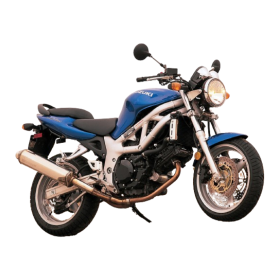
Suzuki 1999 SV650 Service Manual (399 pages)
Brand:
Suzuki
| Category:
Motorcycle
| Size: 76.25 MB
Table of Contents
Foreword
2
Group Index
2
How to Use this Manual
3
To Locate What You Are Looking for
3
Component Parts and Work to be Done
3
Symbol
4
General Information
5
Contents
5
Warning/Caution/Note
6
General Precautions
6
Suzuki SV650X ('99-Model) View
8
Right Side
8
Left Side
8
Serial Number Location
8
Fuel, Oil and Engine Coolant Recommendation
9
Engine Oil
9
Brake Fluid
9
Front Fork Oil
9
Anti-Freeze/Engine Coolant
10
Liquid Amount of Water/Engine Coolant
10
Break-In Procedures
10
Cylinder Identification
10
Information Labels
11
Specifications
12
Dimensions and Dry Mass
12
Electrical
13
Capacities
13
Country and Area Codes
14
Periodic Maintenance
15
Periodic Maintenance Schedule
16
Periodic Maintenance Chart
16
Lubrication Points
17
Maintenance and Tune-Up Procedures
18
Air Cleaner
18
Front Spark Plug Removal
19
Rear Spark Plug Removal
20
Heat Range
21
Carbon Deposits
21
Spark Plug Gap
21
Spark Plug Installation
21
Tappet Clearance
22
Tappet Clearance Adjustment
24
Intake Side
25
Tappet Shim Selection Table (Intake)
25
How to Use this Chart
25
Exhaust Side
26
Tappet Shim Selection Table (Exhaust)
26
Engine Oil and Oil Filter
27
Engine Oil Replacement
27
Oil Filter Replacement
28
Necessary Amount of Engine Oil
28
Fuel Hose
29
Engine Idle Speed
29
Throttle Cable Play
30
Clutch Cable Play
31
Engine Coolant Level Check
32
Engine Coolant Change
32
Air Bleeding the Cooling Circuit
33
Radiator Hoses
33
Drive Chain
34
Checking
34
Adjusting
35
Cleaning and Lubricating
35
Brake Fluid Level Check
36
Brake Pads
37
Brake Pedal Height
37
Brake Light Switch
37
Air Bleeding from Brake Fluid Circuit
38
Tire Tread Condition
39
Tire Pressure
40
Steering
40
Front Fork
41
Rear Suspension
41
Exhaust Pipe Bolt and Nut
41
Chassis Bolts and Nuts
42
Compression Pressure Check
44
Compression Pressure Specification
44
Compression Test Procedure
44
Oil Pressure Check
45
Oil Pressure Specification
45
Low Oil Pressure
45
High Oil Pressure
45
Engine
46
Engine Components Removable with the Engine in Place
47
Engine Left Side
47
Engine Right Side
47
Engine Center
47
Engine Removal
48
Engine Installation
58
Exhaust Gas Sealer: Permatex 1372
63
Engine Disassembly
65
Cylinder Head Cover
66
Front Camshafts
66
Rear Camshafts
68
Front Cylinder Head
70
Rear Cylinder Head
71
Front Cylinder
72
Rear Cylinder
72
Piston
73
Starter Motor
73
Oil Filter
73
Generator Cover
74
Clutch Cover
74
Clutch
75
Gearshift System
76
Oil Pipe
77
Primary Drive Gear
77
Rear Cam Chain
78
Generator Rotor
78
Front Cam Chain
79
Oil Pump
81
Neutral Indicator Light Switch
82
Crankcase
82
Crankshaft
83
Transmission
83
Engine Components Inspection and Service
85
Camshaft Identification
85
Cam Wear
85
Camshaft Journal Wear
86
Camshaft Runout
87
Cam Chain Tension Adjuster
87
Cam Chain Tensioner
87
Cam Chain Guide
87
Cylinder Head and Valve
88
Valve and Valve Spring Disassembly
88
Cylinder Head Distortion
89
Valve Stem Runout
89
Valve Head Radial Runout
89
Valve Face Wear
89
Valve Stem Deflection
90
Valve Stem Wear
90
Valve Guide Servicing
90
Valve Seat Width Inspection
91
Valve Seat Servicing
92
Initial Seat Cut
92
Top Narrowing Cut
93
Bottom Narrowing Cut
93
Final Seat Cut
93
Valve Stem End Condition
95
Valve Spring
95
Valve and Valve Spring Reassembly
96
Intake Pipe
97
Exhaust Pipe
98
Water Union
98
Cylinder Distortion
98
Cylinder Bore
98
Piston and Piston Ring
99
Piston Diameter
99
Piston-To-Cylinder Clearance
99
Piston Ring-To-Groove Clearance
99
Piston Ring Free End Gap and Piston Ring End Gap
100
Oversize Piston Ring
100
Oversize Oil Ring
100
Piston Ring Reassembly
101
Piston Pins and Pin Bore
102
Conrod and Crankshaft
102
Conrod Small End I.D.
102
Conrod Big End Side Clearance
103
Conrod Removal and Bearing Inspection
103
Conrod-Crank Pin Bearing Selection
104
Bearing Selection Table
104
Conrod I.D.
105
Crank Pin O.D.
105
Bearing Thickness
105
Conrod and Bearing Reassembly
105
Crankshaft Journal Bearing
106
Inspection
106
Selection
107
Crank Shaft Journal I.D.
107
Replacement
108
Removal
108
Installation
109
Crankshaft Thrust Bearing
112
Bearing and Oil Seal
113
Bearing Remover Attachment
114
Bearing Installer Attachment
114
Oil Pressure Switch
115
Oil Pressure Regulator
116
Oil Strainer Cleaning
116
Oil Plate
117
Oil Jet
118
Gearshift Arm Stopper
119
Clutch Drive Plates
120
Clutch Driven Plates
120
Clutch Spring
120
Clutch Bearing Inspection
121
Primary Driven Gear Assembly
121
Gearshift Shaft/Gearshift Arm
122
Countershaft Disassembly
123
Driveshaft Disassembly
124
Gearshift Fork to Groove Clearance
128
Gearshift Fork Groove Width
128
Gearshift Fork Thickness
128
Starter Clutch
129
Generator and Signal Generator
130
Oil Pump Inspection
131
Engine Reassembly
132
Gearshift
132
Engine Sprocket Spacer
135
Cam Chain Drive Sprocket
137
Cylinder
151
Cam Timing
156
Front Camshaft
156
Rear Camshaft
160
Camchain Tension Adjuster
162
Fuel and Lubrication System
167
Fuel System
168
Fuel Pump Operation
169
Intake Process
169
Discharge Process
169
Control of Fuel Pressure
169
Fuel Tank Lift-Up
170
Fuel Tank
171
Remounting
172
Vacuum Fuel Valve
172
Inspection and Cleaning
173
Fuel Level Indicator Light Switch
174
Fuel Pump
175
Carburetor Construction
177
I.D. No. Location
179
Diaphragm and Pistor Operation
180
Slow System
181
Transient Enrichment System
181
Main System
182
Starter (Enricher) System
183
Float System
183
Carburetor
184
Disassembly
186
Carburetor Cleaning
193
Carburetor Inspection
193
Needle Valve Inspection
193
Fuel Filter Inspection
194
Float Height Adjustment
194
Throttle Position Sensor Inspection
194
Carburetor Heater Inspection (Only for E-02 Model)
195
Carburetor Heater-Switch Inspection (Only for E-02 Model)
195
Reassembly and Remounting
196
(Only for E-02 Model)
196
Carburetor Heater (Only for E-02 Model)
196
Coasting Valve
197
Funnel
197
Pilot Screw
197
Carburetor Top Cap
197
Throttle Position Sensor Positioning
199
Carburetor Clamps
200
Carburetor Synchronization
201
Calibrating each Gauge
201
Fuel Level Adjustment
204
Oil Strainer
205
Engine Lubrication System Chart
206
Engine Lubrication System
207
Front Cylinder View
207
Rear Cylinder View
208
Cooling System
209
Engine Coolant
210
Cooling Circuit Inspection
211
Radiator and Water Hoses
212
Radiator Removal
212
Radiator Cap Inspection
213
Radiator Inspection and Cleaning
213
Water Hose Inspection
213
Radiator Remounting
214
Cooling Fan
214
Cooling Fan Thermo-Switch
215
Engine Coolant Temperature Switch
216
Thermostat
217
Water Pump
220
Bearing
223
Mechanical Seal
223
Oil Seal
224
Seal Washer
224
Reassembly and Installation
224
Chassis
229
Exterior Parts Construction
230
Rear Seat
231
Frame Side Cover
231
Front Seat
231
Front Fender
231
Seat Tail Cover
232
Front Wheel Construction
233
Speed Sensor
236
Wheel Bearing
236
Front Wheel
236
Front Axle
236
Brake Disc
237
Front Fork Construction
239
Inner and Outer Tubes
242
Fork Spring
242
Steering Construction
247
Handlebars
248
Steering Removal
251
Steering Inspection and Disassembly
252
Steering Installation
254
Steering Tension Adjustment
256
Rear Wheel Construction
257
Wheel Damper
260
Rear Wheel
260
Rear Axle
260
Sprocket
261
Rear Suspension Construction
265
Rear Shock Absorber and Cushion Rod
267
Spacer
267
Rear Shock Absorber
268
Swingarm
269
Chain Buffer
271
Swingarm Pivot Shaft
271
Suspension Setting
273
Spring Pre-Load Adjustment
273
Front Brake Construction
274
Brake Fluid Replacement
275
Brake Pad Replacement
276
Front Brake Caliper
276
Brake Caliper Inspection
277
Brake Caliper Piston Inspection
277
Front Master Cylinder
279
Rear Brake Construction
283
Rear Brake Caliper
285
Rear Master Cylinder
289
Tire and Wheel
292
Tire Removal
292
Wheel Inspection
292
Tire Inspection
292
Valve Inspection
293
Valve Installation
293
Tire Installation
293
Cold Inflation Tire Pressure
294
Electrical System
295
Cautions in Servicing
296
Connector
296
Coupler & Clamp
296
Semi-Conductor Equipped Part
296
Connecting Battery
297
Wiring Procedure
297
Using Multi Circuit Tester
297
Location of Electrical Components
298
Charging System
301
Description
301
Function of Regulator
301
Battery Current Leak Inspection
304
Charging Output Inspection
304
Generator Coil Resistance Inspection
305
Generator No-Load Performance Inspection
305
Regulator/Rectifier Inspection
305
Starter System and Side-Stand Ignition Interlock System Description
306
Starter Motor Removal and Disassembly
309
Starter Motor Inspection
309
Carbon Brushes
309
Commutator
310
Armature Coil Inspection
310
Oil Seal Inspection
310
Starter Motor Reassembly
310
Starter Relay Inspection
313
Side Stand/Ignition Interlock System Parts Inspection
314
Neutral Switch
314
Side-Stand Switch
315
Turn Signal/Side-Stand Relay
315
Side-Stand Relay Inspection
315
Diode Inspection
316
Ignition System (Digital Ignitor)
317
Ignition Coil Primary Peak Voltage
319
Ignition Coil Resistance
320
Signal Generator Peak Voltage
321
Signal Generator
322
Speedometer
323
Bulb Replacement
324
Construction
325
Fuel Level Indicator Light Inspection
327
Oil Pressure Indicator Light Inspection
328
Water Temperature Indicator Light Inspection
328
Speed Sensor Inspection
329
Relays
330
Turn Signal Side-Stand Relay
330
Brake Light/Taillight
333
Turn Signal Lights
333
Switches
334
Ignition Switch Removal
335
Battery Specifications
336
Initial Charging
336
Filling Electrolyte
336
Servicing
337
Recharging Operation
338
Servicing Information
339
Troubleshooting
340
Wiring Diagram (for U.S.A. and Canada Models)
348
Wiring Diagram (for E-24 Model)
349
Wiring Diagram (for E-02, 04, 17, 18, 22, 25 and 34 Models)
350
Wiring Harness, Cable and Hose Routing
351
Speed Sensor Lead Wire Routing
353
Cable Routing
354
Fuel System Hose Routing
355
Cooling System Hose Routing
357
Front Brake Hose Routing
358
Rear Brake Hose Routing
359
Pair (Air Supply) System Hose Routing
360
Fuel Tank Set-Up
361
Special Tools
362
Tightening Torque
365
Tightening Torque Chart
368
Service Data
369
Valve + Guide
369
Camshaft + Cylinder Head
370
Conrod + Crankshaft
371
Transmission + Drive Chain
372
Thermostat + Radiator + Fan + Coolant
372
Wattage
374
Brake + Wheel
375
Tire
376
Suspension
376
Fuel + Oil
377
Emission Control Information
378
Emission Control Carburetor Components
379
Evaporative Emission Control System (California Model Only)
380
Canister Hose Routing (California Model Only)
381
Hoses
382
Canister
382
Tank Pressure Control Valve
382
Pair (Air Supply) System Diagram
383
Hoses and Pipes
385
Reed Valve of Pair Control Valve
385
Pair Control Valve
385
SV650Y ('00-Model)
386
Cylinder + Piston + Piston Ring
389
Advertisement
Advertisement
Related Products
Suzuki 1999 VZ800
Suzuki 1999 GSX-R750
Suzuki 1998 VZ800
Suzuki 1997 VZ800
Suzuki 1997 GSX-R750
Suzuki 1996 GSX-R750
Suzuki 1994 GS500ER
Suzuki 1995 GS500ES
Suzuki 1996 GS500ET
Suzuki 1997 GS500EV
Suzuki Categories
Motorcycle
Automobile
Motorcycle Accessories
Musical Instrument
Offroad Vehicle
More Suzuki Manuals
Login
Sign In
OR
Sign in with Facebook
Sign in with Google
Upload manual
Upload from disk
Upload from URL