Sign In
Upload
Manuals
Brands
Siemens Manuals
Controller
HydroRanger 200
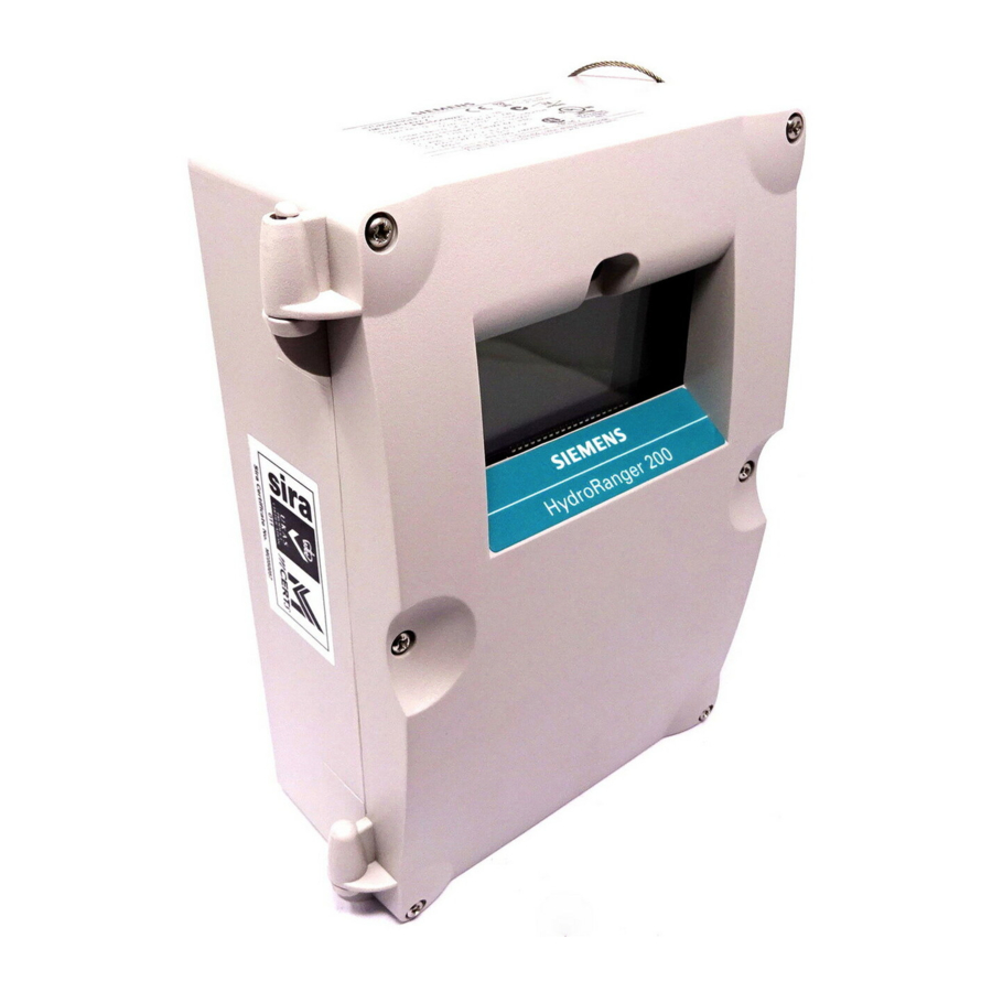
Siemens HydroRanger 200 Level Controller Manuals
Manuals and User Guides for Siemens HydroRanger 200 Level Controller. We have
1
Siemens HydroRanger 200 Level Controller manual available for free PDF download: Instruction Manual
Siemens HydroRanger 200 Instruction Manual (280 pages)
Brand:
Siemens
| Category:
Controller
| Size: 3.03 MB
Table of Contents
Table of Contents
3
The Hydroranger 200
11
Hydroranger 200 [1 or 3 Relay Model]
11
Hydroranger 200 [6 Relay Model]
11
The Manual
11
Manual Symbols
12
Configuration Examples
12
Specifications
13
Temperature Compensation
14
Installation
18
Mounting
18
Mounting Locations
18
Mounting Instructions
19
Wall Mount
19
Cable Routed through a Conduit
20
Panel Mount
21
Mounting the Enclosure
22
Hydroranger 200 Board
23
Board View
23
Installing the Battery
23
Installing Smartlinx Card
24
Wiring
25
Terminal Board
26
Cables
26
Transducers
27
Relays
27
Temperature Sensor
28
Ma Input [6 Relay Model]
28
Ma Output
28
Level System Synchronization
29
Power
29
Digital Communications
30
RS-232 Serial Connection
30
Discrete Inputs
30
Operating the Hydroranger 200
31
RUN Mode
31
Readings in RUN Mode
32
Status Parameters
33
Controlling the Display
34
Adjusting the Primary Reading for Four-Digit LCD Readout
34
Auxiliary Reading
34
Multiple Readings [6 Relay Model]
35
PROGRAM Mode
36
Starting PROGRAM Mode
36
Hand Programmer
36
Programmer Keys
37
Dolphin Plus
38
Dolphin Plus Toolbar Buttons
39
SIMATIC Process Device Manager (PDM)
40
Device Description
40
Activating the Hydroranger 200
41
Changing Parameters
41
Security
42
Using Units or Percent (%)
42
Parameters Types
42
Parameter Reset
43
Display Readout
43
Parameter Indexing
44
Primary and Secondary Indexes
45
Primary Index
45
Secondary Index
45
Starting Measurement
46
Single Point Models
46
Average or Differential [6 Relay Model]
47
Dual Point Models
47
Measurement Conditions
48
Response Rate
48
Dimensions [6 Relay Model]
48
Failsafe
48
Relays
49
General Introduction
49
Relay Function
49
Alarm
49
Pump
50
Miscellaneous
50
Relay Status - Non Run Modes
51
Relay States
51
Relay Related Parameters
51
Relay Wiring Test
52
Relay Activation
52
Relay Failsafe
53
Preset Applications
54
Backup Level Override
55
Backup Level Override Parameters
55
Discrete Inputs
56
Wiring the Discrete Inputs
56
Programming the Discrete Input Logic
56
Ma I/O
57
Ma Input [6 Relay Model]
57
Ma Output
57
Volume [6 Relay Model]
59
Readings
59
Tank Shape and Dimensions
59
Characterization Chart [6 Relay Model]
60
Example Chart
60
Hydroranger 200 [6 Relay Model]
61
Alarms
62
Level
62
Setting Simple Level Alarms
63
Rate [6 Relay Model]
63
In Bounds/ out of Bounds Range [6 Relay Model]
64
Temperature Alarm
64
Cable Fault
64
Temperature [6 Relay Model]
64
Loss of Echo (LOE)
65
Pump Control
66
Setting a Pump down Group
66
Setting a Pump up (Reservoir) Group
67
Other Pump Control Algorithms
69
Set Relays to ALTERNATE DUTY BACKUP [6 Relay Model]
69
Set Relays to FIXED DUTY ASSIST
69
Set Relays to FIXED DUTY BACKUP [6 Relay Model]
70
Set Relays to ALTERNATE DUTY SERVICE [6 Relay Model]
70
Set Relays to FIRST in FIRST out (FIFO) ASSIST [6 Relay]
71
Optional Pump Controls
71
Starting Pumps by Rate of Level Change [6 Relay Model]
71
Rotating Pumps by Service Ratio [6 Relay Model]
72
Totalizing Pumped Volume [6 Relay Model]
73
Setting Independent Failsafe Controls
73
Setting a Pump to Run on [6 Relay Model]
74
Setting the Pump Start Delays [6 Relay Model]
74
Reducing Wall Cling [6 Relay Model]
74
Grouping Pumps [6 Relay Model]
75
Setting a Flush Valve [6 Relay Model]
75
Relay Controlled by Communications
76
Tracking Pump Usage
76
Rake (Screen) Control [6 Relay Model]
77
Setting a Rake Control
77
Setting the Common Parameters
78
Set Relay 1 (Operate Rake)
78
Set Relays 2 to 4 (Level Alarms)
78
External Totalizers and Flow Samplers [6 Relay Model]
79
Relay Contacts
79
Totalizer
79
Flow Sampler
80
Based on Volume and Time
80
Open Channel Monitoring (OCM) [6 Relay Model]
81
Common Parameters
81
Setting Zero Head
82
Setting Totalized Volume
83
Applications Supported by Hydroranger 200 [6 Relay Model]
83
BS-3680 / ISO 1438/1 Thin Plate V Notch Weir
83
BS-3680 / ISO 4359 Rectangular Flume
84
Palmer Bowlus Flume
85
H Flume
86
Pmds with Exponential Flow to Head Function
87
Applicable Weir Profiles
87
Non-Applicable Weir Profiles
88
Parshall Flume
88
Leopold Lagco Flume
89
Cut Throat Flume
90
Universal Calculation Support
91
Typical Flow Characterization
91
Example Flumes
92
Example Weirs
92
Testing the Configuration
93
Simulation
93
Simulating a Single Measurement
93
Simulating a Level Cycle
93
Checking Volume Characterization [6 Relay Model]
94
Checking OCM Flow Characterization [6 Relay Model]
94
I/O Checkout
95
Application Test
95
Hydroranger 200 Communications
97
Hydroranger 200 Communication Systems
97
Optional Smartlinx®Cards
98
Communication Systems
98
Communication Ports
98
Modbus
99
Smartlinx
99
Dolphin Plus
99
Communications Installation
100
Wiring Guidelines
100
Ports 1 and 2
100
Ports 1 and 2: RS-232 RJ-11 Jack and RS-485 Locations
100
Port 1: RS-232 RJ-11 Jack
101
Port 2: RS-485
101
Configuring Communication Ports (Parameters)
102
Modbus Register Map
105
Word Order (R40,062)
106
Map ID (R40,063)
106
Product ID (R40,064)
107
Point Data (R41,010 - R41,031)
107
Totalizer (R41,040 - R41,043)
107
Input/Output (R41,070 - R41,143)
108
Discrete Inputs (R41,070)
108
Relay Outputs (R41,080)
108
Ma Input (R41,090) [6 Relay Model]
108
Ma Output (R41,110-41,111)
108
Pump Control (R41,400 - R41,474)
108
Pump on Setpoint (R41,420 - R41,425)
108
Pump off Setpoint (R41,430 - R41,435)
109
Pumped Volume (R41,440 - R41,443) [6 Relay Model]
109
Pump Hours (R41,450 - R41,461)
109
Pump Starts (R41,470 - R41,475)
109
Parameter Access (R43,998 - R46,999)
110
Parameter Indexing
110
Indexing the Parameter Access Area
110
Reading Parameters
111
Global Index Method (P782 = 0)
111
Parameter Specific Index Method (P782 = 1)
112
Writing Parameters
112
Global Index Method (P782 = 0)
112
Format Words (R46,000 to R46,999)
113
Global Index Method (P782 = 0)
113
Parameter-Specific Index Method (P782 = 1)
113
Format Registers
113
Data Types
115
Numeric Values
115
Bit Values
115
Unsigned Double Precision Integer (UINT32)
115
Split Values
116
Text Messages
117
Relay Function Codes (P111 Only)
118
Error Handling
119
Modbus Responses
119
Communication Troubleshooting
121
Generally
121
Specifically
121
Communication Appendix A: Single Parameter Access (SPA)
122
Mapping
122
Reading Parameters
122
Writing Parameters
123
Format Register
123
Error Codes
124
Parameter Reference
125
Hydroranger 200 - 1, 3, or 6 Relay Models
125
Helpful Hints
125
Index Types
126
Quick Start (P001 to P007)
127
P000 Lock
127
For DPD and DPA Programming [6 Relay Model]
128
Volume (P050 to P055) [6 Relay Model]
131
Display and Reading (P060 to P062)
136
Backup Level Override
138
Failsafe (P070 to P072)
140
Relays (P100 to P119)
141
Hydroranger 200 [6 Relay Model]
143
Pump Setpoint Modifiers (P121 and P122) [6 Relay Model]
148
Independent Relay Failsafe (P129)
149
Advanced Pump Control Modifiers (P130 to P137) [6 Relay Model]
150
Flush Systems (P170 to P173) [6 Relay Model]
153
Ma Output (P200 to P219)
155
Independent Ma Setpoints (P210 and P211)
158
Ma Output Limits (P212 and P213)
158
Ma Output Trim (P214 to P215)
159
Ma Output Failsafe (P219) [6 Relay Model]
160
Ma Input (P250 to P260) [6 Relay Model]
160
Discrete Input Functions (P270 to P275)
163
Standard Data Logging (P300 to P321)
164
Record Temperatures (P300 to P303)
164
Record Readings (P304 and P305)
166
Pump Records (P309 to P312)
166
Flow Records (P320 and P321) [6 Relay Model]
167
LCD Totalizer (P322 and P323) [6 Relay Model]
168
Profile Records (P330 to P337)
169
Auto Record on and off Setpoints (P334 to P337)
172
Installation Records (P340 to P342)
174
Open Channel Monitoring (P600 to P621) [6 Relay Model]
175
Example Exponents
177
Pumped Volume Totalizer (P622) [6 Relay Model]
184
Totalizer (P630 to P645) [6 Relay Model]
185
Range Calibration (P650 to P654)
188
Temperature Compensation (P660 to P664)
191
Rate (P700 to P708)
193
Measurement Verification (P710 to P713)
197
Transducer Scanning (P726 to P729)
200
Display (P730 to P739)
201
Smartlinx Reserved (P750 to P769)
204
Communications (P770 to P782)
204
Smartlinx Hardware Testing (P790 to P795)
207
Echo Processing (P800 to P807)
209
Advanced Echo Processing (P815 to P825)
213
Advanced TVT Adjustment (P830 to P835)
217
Advanced Shot Adjustment (P840 to P852)
222
Test (P900 to P913)
225
Measurement (P920 to P927)
228
Master Reset (P999)
231
Appendix A: Index Types
233
Index Types
233
Appendix B: Technical Reference
234
Transmit Pulse
234
Echo Processing
234
TVT (Time Varying Threshold) Curves
235
Auto False-Echo Suppression
235
Distance Calculation
236
Sound Velocity
236
Scanning
237
Volume Calculation [6 Relay Model]
237
Universal, Curved [6 Relay Model]
238
Flow Calculation [6 Relay Model]
238
Universal, Linear [6 Relay Model]
239
Universal, Curved [6 Relay Model]
239
Maximum Process Speed
240
Appendix C: Troubleshooting
241
Common Problems Chart
241
Noise Problems
242
Determine the Noise Source
242
Non-Transducer Noise Sources
243
Common Wiring Problems
243
Reducing Electrical Noise
243
Reducing Acoustical Noise
243
Measurement Difficulties
244
Flashing LOE Display
244
Adjust Transducer Aiming
244
Increase Failsafe Timer Value
245
Install a Transducer with a Narrower Beam
245
Use Dolphin Plus to Debug Echo
245
Fixed Reading
245
Obstructions in the Sound Beam
245
Nozzle Mountings
245
Set the Hydroranger 200 to Ignore the Bad Echo
246
Wrong Reading
246
Types of Wrong Readings
246
Liquid Splashing
246
Adjust the Echo Algorithm
246
Transducer Ringing
247
Unit Repair and Excluded Liability
248
Appendix D: Pump Control Reference
249
Pump Control Options
249
Pump Groups
249
Pump by Rate [6 Relay Model]
249
Pump Control Algorithms
249
Fixed Duty Assist (P111 = 50)
250
Fixed Duty Backup (P111 = 51) [6 Relay Model]
250
Alternate Duty Assist (P111 = 52)
251
Alternate Duty Backup (P111 = 53) [6 Relay Model]
251
Service Ratio Duty Assist (P111 = 54) [6 Relay Model]
252
Service Ratio Duty Backup (P111 = 55) [6 Relay Model]
253
First in First out (FIFO) (P111 = 56) [6 Relay Model]
253
Pump by Rate (P121) [6 Relay Model]
253
Other Pump Controls [6 Relay Model]
253
Appendix E: Updating Software
255
Updating Software
255
Appendix F: Upgrading
256
Mounting a Hydroranger 200 (All Models)
256
Connecting the Transducer
256
Coaxial Transducer Extention
256
Connecting a Transducer with RG62 Coaxial Extension Cable
257
Hydroranger to Hydroranger 200 Parameters
258
Appendix G: Conduit Entry for Class 1, DIV 2 Applications
259
Appendix H: Software Revision History
261
Programming Charts
265
Advertisement
Advertisement
Related Products
Siemens HiPath C100
Siemens HMI 128PT
Siemens HMI 2048PT
Siemens HMI 512PT
Siemens HY738356M
Siemens HY738357M
Siemens HB43.S SERIES
Siemens HK 162..EU
Siemens HS736G1 2 Series
Siemens HB378GT 0 Series
Siemens Categories
Industrial Equipment
Controller
Oven
Control Unit
Washer
More Siemens Manuals
Login
Sign In
OR
Sign in with Facebook
Sign in with Google
Upload manual
Upload from disk
Upload from URL