Sign In
Upload
Manuals
Brands
Schweitzer Engineering Laboratories Manuals
Measuring Instruments
SEL-734
Schweitzer Engineering Laboratories SEL-734 Manuals
Manuals and User Guides for Schweitzer Engineering Laboratories SEL-734. We have
2
Schweitzer Engineering Laboratories SEL-734 manuals available for free PDF download: Instruction Manual, Quick Start Manual
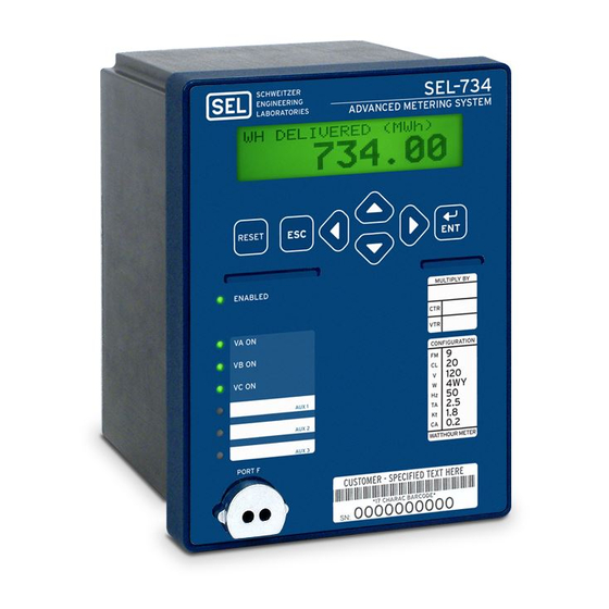
Schweitzer Engineering Laboratories SEL-734 Instruction Manual (344 pages)
Advanced Metering System
Brand:
Schweitzer Engineering Laboratories
| Category:
Measuring Instruments
| Size: 6.3 MB
Table of Contents
Table of Contents
3
List of Tables
7
List of Figures
11
Preface
13
Section 1: Introduction and Specifications
19
Overview
19
SEL-734 Meter Forms and Models
19
Table 1.1 SEL-734 Form Numbers
19
Table 1.2 SEL-734 Feature Availability
20
Applications
21
Figure 1.1 SEL-734 Applied at Billing Points Throughout the Power System
21
Hardware Connection Features
22
Figure 1.2 SEL-734 Inputs, Outputs, and Communications Ports
22
Figure 1.3 SEL-734 Extra I/O Board (Expansion Slot #2)
23
Communications Connections
24
Figure 1.4 SEL-734 Communications Connection Examples
24
Specifications
25
Section 2: Installation
29
Overview
29
Meter Mounting
29
Figure 2.1 SEL-734 Horizontal Panel-Mount Dimensions
29
Figure 2.2 SEL-734 Vertical Panel-Mount Dimensions
30
Figure 2.3 SEL-734 Easily Extractable Meter (EXM) Mounting Dimensions
30
Connection Diagrams
31
Figure 2.4 SEL-734 Horizontal Front-Panel Drawing
31
Figure 2.6 Rear-Panel Drawings for Model 0734ES2-6X
33
Making Rear-Panel Connections
34
Figure 2.7 Grounding Terminal Symbol
34
Table 2.1 SEL-734 Power Supply Fuse Requirements
35
Figure 2.8 Form 9, 3-Element, 4-Wire Wye
37
Figure 2.9 Form 5, 2-Element, 3-Wire Delta
38
Table 2.2 Expansion Slot C (#1) Circuit Board Jumper J7 Information
39
Figure 2.10 J7 Internal Telephone Modem Jumper Positions
39
Figure 2.11 J7 Location on the Auxiliary Communication Board
39
Table 2.3 Communication Cables Used to Connect the SEL-734 to Other Devices
40
Table 2.4 Optical Port Probes
41
Circuit Board Connections
42
Section 3: PC Software
45
Overview
45
Installing the Computer Software
45
Table 3.1 System Requirements for AC SEL ERATOR Quickset
45
Installation
46
Starting AC SEL ERATOR Quickset
46
Section 4: Metering
47
Overview
47
Four-Quadrant VAR Metering
48
Figure 4.1 IEEE VAR Sign Convention
48
Instantaneous Metering
49
Table 4.1 Metering Quantity Definitions
49
Figure 4.2 SEL-734 Power Flow Notations
49
Demand Metering
51
Figure 4.3 Response of Thermal, Rolling, and Block Demand Meters to a Step Input (Setting DMTC=15 Minutes)
52
Table 4.2 Demand Meter Settings and Settings Ranges
54
Table 4.3 Time = 5 Minutes Intervals
54
Table 4.4 Time = 10 Minutes Intervals
54
Table 4.5 Time = 15 Minutes Intervals
55
Table 4.6 Demand Meter Settings and Settings Range
56
Figure 4.5 PREDAL Logic
56
Figure 4.6 Demand Current Logic Outputs
57
Energy Metering
59
Table 4.7 Example ANGCUT Setting
59
Energy Interface
60
Table 4.8 Energy Interface Table
60
Maximum/Minimum Metering
62
Figure 4.7 FAULT and DFAULT Meter Word Bit Logic
63
Crest Factor Metering
64
Harmonic Metering
65
Transformer/Line Loss Compensation
67
Table 4.9 MET H Command
67
Figure 4.8 Meter and Billing Positions
67
Table 4.10 Meter Power Calculation Corrections According to Meter Position
68
Table 4.11 Analog Values Affected by Transformer/Line Loss Compensation
68
Table 4.12 Required User Input
69
Figure 4.9 Example System Values
71
Table 4.13 Settings for Example Loss Calculations
72
Load Profile Report
74
Table 4.14 Load Profile Recorder Settings and Commands
74
Table 4.15 LDP Serial Port Commands
75
Table 4.16 LDP File Transfer Commands
77
Table 4.17 LDP Field Format
77
Table 4.18 Meter Configuration Record
78
Table 4.19 SEL-734 Load Profile Record Response
80
Table 4.20 Record Type 0065-Present Values
80
Table 4.21 Record Type 0066-Meter Status
80
Table 4.22 Record Type 0067-LDP Data
81
Table 4.23 Status Nibble Definitions
81
Metering Calculations
82
Table 4.24 Record Type 0068-SER Data
82
Table 4.25 Record Type 0069-LDP Error
82
Section 5: Time-Of-Use
85
Introduction
85
Settings
85
TOU Setup
86
Figure 5.1 Setup Page
86
Figure 5.2 Rate Schedules Page
87
Figure 5.3 Schedule Drop-Down Menu
87
Figure 5.4 Deleting a Rate Schedule
88
Figure 5.5 Renaming a Rate Schedule
88
Figure 5.6 Modifying a Rate Schedule
89
Figure 5.7 Calendar Page
90
Figure 5.8 Calendar Entry Drop-Down Menu
91
Figure 5.9 Calendar Entry Editor
91
Figure 5.10 Calendar Entry Editor
91
Figure 5.11 Quick Set Menu
92
Figure 5.12 TOU Data Page
92
Table 5.1 Available Time-Of-Use Data
93
TOU Glossary
95
Figure 5.13 Total At/Since Demand Reset
95
Figure 5.14 Peak Cumulative Demand
96
Section 6: Power Quality and Event Analysis
99
Overview
99
Event Reports
100
Figure 6.1 Standard Event Report Summary
100
Table 6.1 Example EVE Commands
101
Table 6.2 Standard Event Report Current, Voltage, and Frequency Columns
103
Figure 6.2 Typical Auto Message Response
103
Example Standard 15-Cycle Event Report
104
Figure 6.3 Example Standard 15-Cycle Event Report 1/16-Cycle Resolution (Wye-Connected Pts)
105
Sequential Events Recorder (SER) Report
106
Table 6.3 Example SER Serial Port Commands
107
Example Sequential Events Recorder (SER) Report
108
Table 6.4 Sequence of Events Recorder Explanation
108
Figure 6.4 Example Sequential Events Recorder (SER) Event Report
108
Sag/Swell/Interruption (SSI) Report
109
Figure 6.5 AC SEL ERATOR Quickset VSSI Report with CBEMA/ITIC and Disturbance Analysis
109
Figure 6.6 Example SSI Response in AC SEL ERATOR Quickset
110
Table 6.5 Element Status Columns
111
Table 6.6 Status SSI Column
111
Figure 6.7 Example Sag/Swell/Interruption (SSI) Report (Meter Form 9)
111
Figure 6.8 Example Sag/Swell/Interruption (SSI) Report (Meter Form 5)
112
Section 7: Time-Synchronized Measurements
113
Overview
113
Meter Configuration for High-Accuracy Timekeeping
113
Figure 7.1 High-Accuracy Timekeeping Connections
114
Synchrophasor Measurements
115
Table 7.1 Required Synchrophasor Settings
116
Table 7.2 PMDATA Setting for Synchrophasor Fast Message Data Selection (Form 9 Meter)
117
Table 7.3 SEL Fast Message Protocol Format
118
Table 7.4 Unsolicited Write Message Transmission Rates
118
Table 7.5 Minimum Bandwidth Requirements
119
Table 7.6 Unsolicited Fast Message Enable Packet
120
Table 7.7 Unsolicited Fast Message Disable Packet
120
Power Flow Analysis
121
Table 7.8 Meter Voltage and Current Measurement
121
Figure 7.2 500 Kv Three Bus Power System
121
State Estimation Verification
123
Figure 7.3 Power Flow Solution
123
Section 8: Logic
125
Overview
125
Table 8.1 SEL-734 Logic Inputs and Outputs
125
Optoisolated Inputs
126
Figure 8.1 Example Operation of Optoisolated Inputs IN101 through IN102
126
Figure 8.2 Example Operation of Optoisolated Inputs IN401 through IN404, Extra I/O Board (Model 0734ES2-6X)
126
Remote Control Switches
128
Figure 8.3 Remote Control Switches Drive Remote Bits RB01 through RB16
128
Latch Bits
129
Figure 8.4 Traditional Latching Relay
129
Figure 8.5 Latch Control Switches Drive Latch Bits LT01 through LT16
129
Figure 8.6 Battery Charger Health Status Contact Pulses Input IN102 to Enable/Disable ALARM Output Contact
130
Figure 8.7 Single Input to Control ALARM
131
Figure 8.8 Latch Control Switch Operation Time Line
131
Figure 8.9 Latch Control Switch (with Time-Delay Feedback) Operation Time Line
132
SEL OGIC Control Equation Variables/Timers
133
Figure 8.10 SEL OGIC Control Equation Variables/Timers SV01/SV01T through SV16/SV16T
133
Table 8.2 Operator Precedence
134
Math Variables
135
Counter Variables
135
Table 8.3 Counter Inputs and Outputs
135
Figure 8.12 SEL OGIC Variable SV10 Timing Logic
136
KYZ Outputs
137
Table 8.4 KYZ Energy Values
137
Table 8.5 KYZ Output Settings and Ranges
138
Figure 8.14 KYZ Pulse Pickup
138
Output Contacts
139
Figure 8.15 Logic Flow for Example Output Contact Operation
140
Analog Output
141
Table 8.6 Analog Output Settings
141
Figure 8.16 Example SEL-734 Connected to an RTU
141
Rotating Display
142
Table 8.7 Example Connection Details
142
Table 8.8 Display Point Test Definitions
143
Table 8.9 Display Point Formatting
144
Section 9: Settings
147
Overview
147
Table 9.1 Serial Port SET Commands
147
Settings Changes Via the Serial Port
148
Table 9.2 Set Command Editing Keystrokes
148
Meter Word Bits (Used in SEL OGIC Control Equations)
149
Table 9.3 SEL-734 Meter Word Bits
149
Table 9.4 SEL-734 Meter Word Bit Definitions
151
Settings Explanations
157
SEL-734 Settings Sheets
159
Section 10: Communications
171
Overview
171
Communications Options
171
Table 10.1 SEL-734 Meter Models and Available Serial Ports
171
Table 10.2 Modem Settings
172
Figure 10.1 Factory Default at String
172
Table 10.3 Useful at Commands
173
Table 10.4 Useful Dialing Modifiers
173
Port Connector and Communications Cables
174
Figure 10.2 DB-9 Connector Pinout for EIA-232 Serial Ports
174
Table 10.5 Ethernet Port LED Description
175
Table 10.6 Pinout Functions for EIA-232 Serial Ports 2, 3, and 4
175
Figure 10.3 Ethernet Port Status Leds
175
Figure 10.4 Cables for Connecting the SEL-734 to a Computer
176
Figure 10.5 Cable for Connecting the SEL-734 to a DNP Device
177
Figure 10.6 Cable for Connecting the SEL-734 to an External Modem
177
Figure 10.7 Cable for Connecting the SEL-734 to an SEL-2020, SEL-2030, SEL-2032, or SEL-2100
177
Communications Protocols
178
Table 10.7 Serial Communications Port Pin/Terminal Function Definitions
178
Table 10.8 Serial Port Automatic Messages
181
Command Summary
182
Command Explanations
184
Figure 10.8 Using Hyperterminal to Read Settings
187
Table 10.9 MET CF Command Displayed Quantities
189
Table 10.10 MET D Command Displayed Values
189
Table 10.11 MET E Command Displayed Quantities
190
Table 10.12 MET Command Displayed Magnitudes
192
Table 10.13 MET M Command Displayed Quantities
193
Table 10.14 MET PM Displayed Quantities
193
Table 10.15 SHO Command Options
194
Table 10.16 STA Abbreviation Definitions
195
Table 10.17 TAR Command Options
196
Table 10.18 SEL-734 Meter Word and Its Correspondence to TAR Command
196
Table 10.19 SEL-734 Meter Control Subcommands
199
Figure 10.9 Using Hyperterminal to Write Settings
200
Table 10.20 Factory Default Passwords
201
Figure 10.10 Jumper Header-Password and Breaker Jumpers
201
Table 10.21 Main Board Jumpers
202
Table 10.22 STA S Command
202
SEL-734 Meter Command Summary
203
Table 10.23 STA SC and STA SR Command
203
Table 10.24 Command Summary
203
Section 11: Front-Panel Operation
207
Front-Panel Layout
207
Figure 11.1 Meter Front Panel
207
Normal Front-Panel Display
208
Front-Panel Automatic Messages
208
Front-Panel Menus and Operations
208
Table 11.1 Front-Panel Automatic Messages
208
Figure 11.2 Default Display Screen
208
Table 11.2 Front-Panel Pushbutton Functions
209
Figure 11.3 Front-Panel Pushbuttons
209
Figure 11.4 Access Level Security Padlock Symbol
209
Figure 11.5 Password Entry Screen
210
Front-Panel Main Menu
212
Figure 11.6 Front-Panel Main Menu
212
Figure 11.7 Main Menu > Meter Function
212
Figure 11.8 Meter Menu > Instantaneous Meter Display Functions
212
Figure 11.9 Main Menu > Set/Show Function
213
Figure 11.10 Set/Show > Meter Function
213
Figure 11.11 Set Meter > Port Function
213
Figure 11.12 Set/Show > Password Function
214
Section 12: Testing and Troubleshooting
215
Overview
215
Testing Philosophy
215
Testing Methods and Tools
217
Table 12.1 Meter Testing Features
217
Figure 12.1 Typical TEST Mode Connections for an SEL-734 Using a Single-Phase Test Source
218
Figure 12.2 Typical TEST Mode Connections for an SEL-734 Using Three-Phase Test Source
218
Table 12.2 Default Meter Test Pulse Weights
221
Table 12.3 IEEE Recommended Test Pulses
224
Gain Adjustment
225
Table 12.4 Values Affected by WGAIN and VARGAIN
225
Meter Self-Tests
226
Table 12.5 Meter Self-Tests
227
Meter Troubleshooting
228
Meter Calibration
229
Factory Assistance
229
Appendix A: Firmware and Manual Versions
231
Firmware
231
Table A.1 Firmware Revision History
231
Table A.2 Instruction Manual Revision History
237
Appendix Bsel Distributed Port Switch Protocol (LMD)
239
Overview
239
Settings
239
Operation
239
Appendix C: SEL Communications Processors
241
SEL Communications Protocols
241
Table C.1 Supported Serial Command Sets
241
Table C.2 Compressed ASCII Commands
242
SEL Communications Processor
243
Figure C.1 SEL Communications Processor Star Integration Network
243
Table C.3 SEL Communications Processors Protocol Interfaces
244
Figure C.2 Multitiered SEL Communications Processor Architecture
244
SEL Communications Processor and Meter Architecture
245
Figure C.3 Enhancing Multidrop Networks with SEL Communications Processors
246
SEL Communications Processor Example
247
Table C.4 SEL Communications Processor Port 1 Settings
247
Figure C.4 Example SEL Meter and SEL Communications Processor Configuration
247
Table C.5 SEL Communications Processor Data Collection Auto-Messages
248
Table C.6 SEL Communications Processor Port 1 Automatic Messaging Settings
248
Table C.7 SEL Communications Processor Port 1 Region Map
248
Table C.8 Communications Processor METER Region Map
249
Appendix D: Setting SEL
251
OGIC Control Equations
251
Overview
251
Meter Word Bits
251
SEL OGIC Control Equations
252
Table D.2 SEL OGIC Control Equation Settings Limitations for the SEL-734 Meter Model
253
Processing Order and Processing Interval
254
Table D.3 Processing Order of Meter Elements and Logic (Top to Bottom)
254
Appendix E: Distributed Network Protocol
255
Overview
255
Table E.1 VSSI Record Status Report Definitions
257
Table E.2 Phase SSI Column Definitions
257
Configuration
258
Table E.3 SEL-734 DNP3 Default Data Map
258
Table E.4 SEL-734 DNP3 Default Variations
258
Table E.5 DNP3 Device Profile
259
EIA-232 Physical Layer Operation
267
Ethernet Operation
268
Data-Link Operation
268
Table E.6 DNP-IP Specific Settings
268
Data Access Method
269
Device Profile
269
Table E.7 Data Access Methods
269
Table E.8 SEL-734 DNP3 Device Profile
269
Object Table
271
Table E.9 SEL-734 DNP Object List
271
Data Map
273
Table E.10 Event Causes
273
Table E.11 Fault Type
273
Table E.12 Control Field
273
Appendix F: Modbus RTU Communications Protocol
275
Overview
275
Modbus RTU Communications Protocol
275
Table F.1 Modbus Query Fields
275
Table F.2 SEL-734 Meter Modbus Function Codes
276
Table F.3 SEL-734 Meter Modbus Exception Codes
276
Table F.4 01H Read Coil Status Commands
277
Table F.5 Meter Responses to 01H Read Coil Query Errors
277
Table F.6 02H Read Input Status Command
278
Table F.7 SEL-734 Meter Inputs
278
Table F.8 Responses to 02H Read Input Query Errors
278
Table F.9 03H Read Holding Register Command
279
Table F.10 Responses to 03H Read Holding Register Query Errors
279
Table F.11 04H Read Holding Register Command
280
Table F.12 Responses to 04H Read Holding Register Query Errors
280
Table F.13 05H Force Single Coil Command
280
Table F.14 SEL-734 Meter Output Coils (Fc05H)
281
Table F.15 Responses to 05H Force Singe Coil Query Errors
281
Table F.16 06H Preset Single Register Command
281
Table F.17 Responses to 06H Preset Single Register Query Errors
281
Table F.18 08H Loopback Diagnostic Command
282
Table F.19 Responses to 08H Loopback Diagnostic Query Errors
282
Table F.20 10H Preset Multiple Registers Command
282
Table F.21 Responses to 10H Preset Multiple Registers Query Errors
283
Table F.22 Modbus Conversion
284
Table F.23 Modbus Register Map
285
Table F.24 Sequence of Event Enumerations
303
Table F.25 Load Profile Status Enumeration
303
Table F.26 Load Profile Record Status Bits
304
Table F.27 Example Load Profile Status Enumeration
304
Figure F.1 Example Decimal Enumeration
304
Appendix G: MIRRORED BITS Communications
305
Overview
305
Operation
305
MIRRORED BITS Protocol for Pulsar 9600 Baud Modem
308
Settings
308
Table G.2 Matching RX_ID of Local Meter to TX_ID of Remote Meter
309
Appendix H Analog Quantities
311
Table H.1 Instantaneous and RMS Quantities
312
Table H.3 Peak Demand Metering
315
Table H.4 Energy Metering
317
Table H.5 Maximum/Minimum Metering
318
Table H.6 Harmonics Metering
319
Table H.7 Flicker Metering
320
Table H.8 Diagnostics
320
Table H.9 Date/Time
320
Table H.10 SEL OGIC Counters
320
Table H.11 SEL OGIC Math Variables
321
Table H.12 DNP Remote Analog Output Objects
321
Table H.13 Transformer Ratio Settings
321
Table H.14 Prefix and Qualifier Descriptions
321
Table H.15 Time-Of-Use
322
Glossary
325
Index
337
Table H.2 Demand Metering
338
SEL-734 Meter Command Summary
341
Advertisement
Schweitzer Engineering Laboratories SEL-734 Quick Start Manual (16 pages)
Advanced Metering System
Brand:
Schweitzer Engineering Laboratories
| Category:
Measuring Instruments
| Size: 2.23 MB
Advertisement
Related Products
Schweitzer Engineering Laboratories SEL-734W
Schweitzer Engineering Laboratories SEL-787
Schweitzer Engineering Laboratories SEL-700G Series
Schweitzer Engineering Laboratories SEL-700G1
Schweitzer Engineering Laboratories SEL-700GT
Schweitzer Engineering Laboratories SEL-701-1
Schweitzer Engineering Laboratories SEL-787-2
Schweitzer Engineering Laboratories SEL-787-2E
Schweitzer Engineering Laboratories SEL-787-4X
Schweitzer Engineering Laboratories SEL-749M
Schweitzer Engineering Laboratories Categories
Relays
Computer Hardware
Transceiver
Protection Device
Measuring Instruments
More Schweitzer Engineering Laboratories Manuals
Login
Sign In
OR
Sign in with Facebook
Sign in with Google
Upload manual
Upload from disk
Upload from URL