
Related Manuals for Schweitzer Engineering Laboratories SEL-734

Summary of Contents for Schweitzer Engineering Laboratories SEL-734
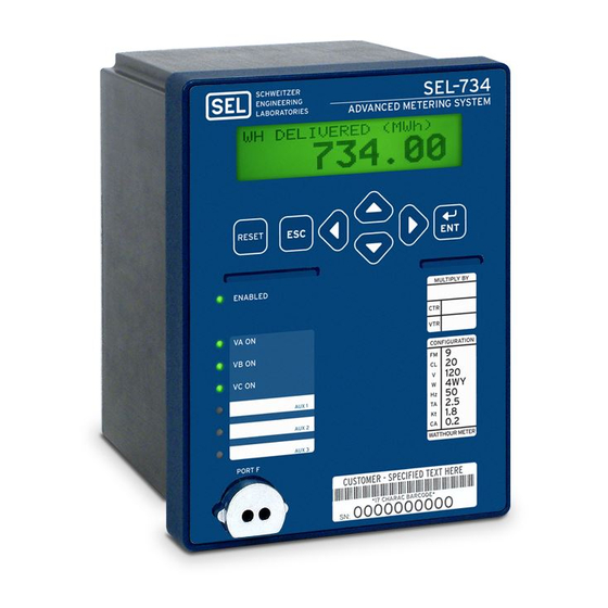
- Page 1 SEL-734 Advanced Metering System Instruction Manual 20090730 *PM734-01-NB* Courtesy of NationalSwitchgear.com...
- Page 2 SEL products appearing in this document may be covered by US and Foreign patents. Schweitzer Engineering Laboratories, Inc. reserves all rights and benefits afforded under federal and international copyright and patent laws in its products, including without limitation software, firmware, and documentation.
-
Page 3: Table Of Contents
List of Figures ..............................ix Preface .................................. xi Section 1: Introduction and Specifications Overview ................................. 1.1 SEL-734 Meter Forms and Models ......................... 1.1 Applications..............................1.3 Hardware Connection Features ........................1.4 Communications Connections......................... 1.6 Specifications ..............................1.7 Section 2: Installation Overview ................................. 2.1 Meter Mounting............................... - Page 4 Communications Options ..........................10.1 Port Connector and Communications Cables ....................10.4 Communications Protocols ..........................10.8 Command Summary ............................10.12 Command Explanations ..........................10.14 SEL-734 Meter Command Summary ......................10.33 Section 11: Front-Panel Operation Front-Panel Layout ............................11.1 Normal Front-Panel Display ..........................11.2 Front-Panel Automatic Messages ........................11.2 Front-Panel Menus and Operations .......................11.2 Front-Panel Main Menu ..........................11.6...
- Page 5 Communications IRRORED Overview ................................ G.1 Operation ................................ G.1 Protocol for Pulsar 9600 Baud Modem ................G.4 IRRORED Settings ................................G.4 Appendix H: Analog Quantities Glossary Index SEL-734 Meter Command Summary Date Code 20090730 Instruction Manual SEL-734 Meter Courtesy of NationalSwitchgear.com...
- Page 6 This page intentionally left blank Courtesy of NationalSwitchgear.com...
-
Page 7: List Of Tables
SEL-734 Power Supply Fuse Requirements ................2.7 Table 2.2 Expansion Slot C (#1) Circuit Board Jumper J7 Information ..........2.11 Table 2.3 Communication Cables Used to Connect the SEL-734 to Other Devices ......2.12 Table 2.4 Optical Port Probes....................... 2.13 Table 3.1 System Requirements for QuickSet .............. - Page 8 SHO Command Options .....................10.24 Table 10.16 STA Abbreviation Definitions ....................10.25 Table 10.17 TAR Command Options .....................10.26 Table 10.18 SEL-734 Meter Word and Its Correspondence to TAR Command ........10.26 Table 10.19 SEL-734 Meter Control Subcommands ................10.29 Table 10.20 Factory Default Passwords ....................10.31 Table 10.21 Main Board Jumpers......................10.32...
- Page 9 Fault Type..........................E.19 Table E.12 Control Field ........................E.19 Table F.1 Modbus Query Fields ......................F.1 Table F.2 SEL-734 Meter Modbus Function Codes................F.2 Table F.3 SEL-734 Meter Modbus Exception Codes................F.2 Table F.4 01h Read Coil Status Commands................... F.3 Table F.5 Meter Responses to 01h Read Coil Query Errors ..............
- Page 10 This page intentionally left blank Courtesy of NationalSwitchgear.com...
-
Page 11: List Of Figures
List of Figures Figure 1.1 SEL-734 Applied at Billing Points Throughout the Power System........1.3 Figure 1.2 SEL-734 Inputs, Outputs, and Communications Ports ............1.4 Figure 1.3 SEL-734 Extra I/O Board (Expansion Slot #2)..............1.5 Figure 1.4 SEL-734 Communications Connection Examples ..............1.6 Figure 2.1... - Page 12 Set Meter > Port Function ....................11.7 Figure 11.12 Set/Show > Password Function ....................11.8 Figure 12.1 Typical TEST Mode Connections for an SEL-734 Using a Single-Phase Test Source..12.4 Figure 12.2 Typical TEST Mode Connections for an SEL-734 Using Three-Phase Test Source ...12.4 Figure C.1 SEL Communications Processor Star Integration Network ..........
-
Page 13: Preface
Preface Manual Overview The SEL-734 Advanced Metering System provides high-accuracy revenue metering and power quality metering for electric utilities and industrial applications. The SEL-734 has OGIC ® flexible, user-programmable SEL control equations that include mathematical functions. The metering and control functions are ideal for complete automation applications. - Page 14 This appendix describes DNP and includes the DNP Port Settings Sheets. Appendix F: Modbus RTU Communications Protocol. ® This appendix describes Modbus RTU communications features supported by the SEL-734 Meter communications port. Appendix G: M Communications. This appendix contains a summary of IRRORED ITS ®...
- Page 15 Earth (Ground) Terminal Laser The SEL-734 is a Class 1 LED Product and complies with IEC 60825-1:1993 + A1:1997 + A2:2001. The following figure shows the compliance label that is located on the left side of the device (when facing the front of the device).
- Page 16 Operation of this equipment in a residential area is likely to cause harmful interference in which serious injury. case the user will be required to correct the interference at his own expense. Class 1 LED Product Compliance Label and Location The following table shows LED information specific to the SEL-734. SEL-734 LED Information Item Detail Max Optical Output: 3.8 mW...
- Page 17 Units must be returned to SEL for repair or replacement. Instructions for Cleaning and Decontamination Use care when cleaning the SEL-734. Use a mild soap or detergent solution and a damp cloth to clean the chassis. Do not use abrasive materials, polish compounds, or harsh chemical solvents (such as xylene or acetone) on any surface.
- Page 18 This page intentionally left blank Courtesy of NationalSwitchgear.com...
-
Page 19: Section 1: Introduction And Specifications
4 wire wye Model numbers are derived from the SEL-734 Model Option Table. For the available options, associated option codes, or to order an SEL-734, refer to the Model Option Table for this product at the SEL website. The SEL-734 offers two options for current classes, CL10 or CL20. The internal hardware of the SEL-734 is identical for both classes. -
Page 20: Table 1.2 Sel-734 Feature Availability
Introduction and Specifications SEL-734 Meter Forms and Models The presence of certain features in a particular SEL-734 varies according to the firmware revision, serial number, and the Power Quality model option. This manual describes features that are not present in some model variations. -
Page 21: Applications
SEL-734 Processor Local Monitoring Plant Net and Control Input/Output SEL-734 SEL-734 SEL-734 SEL-734 Unit Output Auxiliary Process Loads Loads Figure 1.1 SEL-734 Applied at Billing Points Throughout the Power System Date Code 20090730 Instruction Manual SEL-734 Meter Courtesy of NationalSwitchgear.com... -
Page 22: Hardware Connection Features
EIA-485 4 Inputs IRIG-B Telephone Modem 4 Outputs (solid-state EIA-232 EIA-232 or electromechanical) 4 Analog Outputs 4 Solid-State Outputs i4155a Sealing provision Figure 1.2 SEL-734 Inputs, Outputs, and Communications Ports SEL-734 Meter Instruction Manual Date Code 20090730 Courtesy of NationalSwitchgear.com... -
Page 23: Figure 1.3 Sel-734 Extra I/O Board (Expansion Slot #2)
Introduction and Specifications Hardware Connection Features Analog Output/Digital Output Board Input/Output Board (Reference Model 0734ES2-8X) (Reference Model 0734ES2-6X) Figure 1.3 SEL-734 Extra I/O Board (Expansion Slot #2) Date Code 20090730 Instruction Manual SEL-734 Meter Courtesy of NationalSwitchgear.com... -
Page 24: Communications Connections
Connect to the SEL-734 Meters Meter Meter Individually Via the Rear-Panel Serial Ports ETHERNET CONNECTION Port 1 SEL-734 Meter MODEM CONNECTION Port 4B SEL-734 Meter Figure 1.4 SEL-734 Communications Connection Examples SEL-734 Meter Instruction Manual Date Code 20090730 Courtesy of NationalSwitchgear.com... -
Page 25: Specifications
0.75 A L/R = 40 ms 48 Vdc 0.50 A L/R = 40 ms 125 Vdc 0.30 A L/R = 40 ms 250 Vdc 0.20 A L/R = 40 ms Date Code 20090730 Instruction Manual SEL-734 Meter Courtesy of NationalSwitchgear.com... - Page 26 Maximum On 100 mA 10 messages/second (Fnom = 50 Hz) 50 Ω Resistance: typical: The SEL-734 IEEE C37.118-2005 Level 0 performance is specified below: 75 Ω guaranteed: 30 mA Voltage and Current Fnom = 60 Hz ± 5 Hz 75 Ω...
- Page 27 2.5 kV peak differential mode Voltages V ±1% 1.0 kV peak common mode on communication ports Voltages V : ±1% Currents I ±1% Current, Neutral I ±2% Frequency: ±0.01 Hz Date Code 20090730 Instruction Manual SEL-734 Meter Courtesy of NationalSwitchgear.com...
- Page 28 Severity: Response: Class 2 Note: Optional modem not CE compliant. Endurance: Class 1 IEC 60255-21-2:1988 Elec. relays, Part 21: Vibration, shock, bump, and seismic, Section 2, Severity: Response: Class 2 Endurance: Class 1 SEL-734 Meter Instruction Manual Date Code 20090730 Courtesy of NationalSwitchgear.com...
-
Page 29: Section 2: Installation
Section 2 Installation Overview This section provides information you need to install the SEL-734 Meter, including the following topics: ➤ Meter Mounting ➤ Rear-Panel Connection Diagrams ➤ Making Rear-Panel Connections ➤ Circuit Board Connections Meter Mounting Figure 2.1 SEL-734 Horizontal Panel-Mount Dimensions... -
Page 30: Figure 2.2 Sel-734 Vertical Panel-Mount Dimensions
You can mount the SEL-734 in a sheltered indoor environment (a building or an enclosed cabinet) that does not exceed the temperature and humidity ratings for the meter. For voltage and current inputs, the SEL-734 is rated for Measurement Category II, (CAT II) and Pollution Degree 2. This rating allows... -
Page 31: Connection Diagrams
All units can be ordered with an extra I/O or communications card. For model options, view the SEL-734 Model Option Table on the SEL website or contact your local SEL sales representative. Date Code 20090730... - Page 32 Installation Connection Diagrams i4164a Figure 2.5 SEL-734 Vertical Front-Panel Drawing SEL-734 Meter Instruction Manual Date Code 20090730 Courtesy of NationalSwitchgear.com...
-
Page 33: Figure 2.6 Rear-Panel Drawings For Model 0734Es2-6X
Installation Connection Diagrams i4163a i4155a Figure 2.6 Rear-Panel Drawings for Model 0734ES2-6X Date Code 20090730 Instruction Manual SEL-734 Meter Courtesy of NationalSwitchgear.com... -
Page 34: Making Rear-Panel Connections
Refer to Figure 2.6 for rear-panel connections and component location. Required Equipment You will need the following equipment to install SEL-734 rear-panel connections: ➤ Tools: 1/4" (6 mm) slotted-tip screwdriver for current inputs; 5/32" x 1/32" (4 mm x .8 mm) slotted-tip screwdriver for ®... -
Page 35: Table 2.1 Sel-734 Power Supply Fuse Requirements
The SEL-734 internal power supply exhibits low power consumption and a wide-input voltage tolerance. Power Supply Fuse Replacement You can replace a blown or failed fuse in an SEL-734 power supply, or you DANGER can return the SEL-734 to the SEL factory for fuse replacement. If you decide... - Page 36 Specifications on page 1.7 for analog output ratings. Optoisolated Inputs The optoisolated inputs in any of the SEL-734 models (e.g., IN102, IN404) are not polarity dependent. With nominal control voltage applied, each optoisolated input draws between 2–6 mA of current. Refer to Specifications on page 1.7...
-
Page 37: Figure 2.8 Form 9, 3-Element, 4-Wire Wye
Form VC voltage inputs. 9-connected voltages. Frequency is determined from the meter voltage terminals VA-N and VC-N. Form 9 Example SEL-734 Voltage Inputs SEL-734 Current Inputs 3-Phase 4-Wire Wye Figure 2.8 Form 9, 3-Element, 4-Wire Wye... -
Page 38: Figure 2.9 Form 5, 2-Element, 3-Wire Delta
Table 10.1 for information on the serial ports available on the different SEL-734 models. All ports (1, 2, 3, and 4) are independent; therefore, you can communicate to any combination simultaneously. Serial Port 4 on all SEL-734 models with optional communication card consists of an EIA-485 (4A), telephone modem (4B), and an EIA-232 (4C) port. -
Page 39: Table 2.2 Expansion Slot C (#1) Circuit Board Jumper J7 Information
Port Figure 2.11 J7 Location on the Auxiliary Communication Board The SEL-734 optional internal modem complies with Part 68 of the FCC Rules and Regulations. The SEL-734 has a label that contains the FCC Registration Number and Ringer Equivalence Number (REN) of the modem. -
Page 40: Table 2.3 Communication Cables Used To Connect The Sel-734 To Other Devices
80 km. Contact SEL for further information on these products. Table 2.3 Communication Cables Used to Connect the SEL-734 to Other Devices SEL-734 EIA-232 SEL Standard... -
Page 41: Table 2.4 Optical Port Probes
Protocol Specification for ANSI Type 2 Optical Ports. You can communicate with the meter using an ANSI C12.18 optical probe. SEL has tested a variety of optical probes for compatibility with the SEL-734. Table 2.4, although not exhaustive, can be used as a guide for selecting compatible probes. -
Page 42: Circuit Board Connections
Circuit Board Connections Cleaning Use care when cleaning the SEL-734. Use a mild soap or detergent solution and a damp cloth to clean the chassis. Do not use abrasive materials, polishing compounds, or harsh chemical solvents (such as xylene or acetone) on any surface. - Page 43 STA command (see Section 10: Communications). The SEL-734 generates a warning when the battery voltage is less than 2.3 Vdc. If the meter does not maintain the date and time after power loss, replace the CAUTION battery.
- Page 44 This page intentionally left blank Courtesy of NationalSwitchgear.com...
-
Page 45: Section 3: Pc Software
Section 3 PC Software Overview ® Each SEL-734 Meter includes the QuickSet SEL-5030 ERATOR Software program which allows meter configuration, monitoring, testing, and data retrieval. QuickSet offers the following capabilities: ERATOR ➤ ® Create and manage device settings with a Windows interface. -
Page 46: Installation
Step 1. Double-click the QuickSet icon if you have a ERATOR desktop shortcut. Step 2. Choose Programs > SEL Applications and select the QuickSet icon to start the program. ERATOR SEL-734 Meter Instruction Manual Date Code 20090730 Courtesy of NationalSwitchgear.com... -
Page 47: Section 4: Metering
Section 4 Metering Overview This section explains the following SEL-734 Meter metering functions: ➤ Four-Quadrant VAR Metering ➤ Instantaneous Metering ➤ Demand Metering ➤ Energy Metering ➤ Energy Interface ➤ Maximum/Minimum Metering ➤ Crest Factor Metering ➤ Harmonic Metering ➤... -
Page 48: Four-Quadrant Var Metering
Figure 4.1 IEEE VAR Sign Convention The SEL-734 displays VARs in four separate quadrants I–IV: IN-Lagging (I), IN-Leading (II), OUT-Lagging (III), and OUT-Leading (IV). The notations, IN and OUT, used by the SEL-734 are synonymous with delivered and received as shown in Figure 4.2. -
Page 49: Instantaneous Metering
Source Load (Electric Utility) (Industrial Plant) SEL-734 Figure 4.2 SEL-734 Power Flow Notations Four-Quadrant In addition to displaying analog VAR quantities in all four quadrants, Meter Word bits describing the instantaneous VAR quadrants are available (see Meter Word Bits Meter Word Bits (Used in SEL Control Equations) on page 9.3). - Page 50 P_AVE, Q_AVE, or S_AVE Power magnitudes updated every 1 s with 8 kHz data. Power Factor (PF) Displacement power factor calculated using fundamental voltage and current vectors. Updated every 25 ms. SEL-734 Meter Instruction Manual Date Code 20090730 Courtesy of NationalSwitchgear.com...
-
Page 51: Demand Metering
Table 9.1 SEL-734 Settings Sheets Section 9: Settings). Also refer to MET D (Demand Metering) on page 10.19). The SEL-734 provides demand and peak demand metering for the following values: Currents Input currents (A primary) A,B,C,N Power Single-phase megawatts delivered/received... -
Page 52: Figure 4.3 Response Of Thermal, Rolling, And Block Demand Meters To A Step Input (Setting Dmtc=15 Minutes)
(EDEM=ROL) 0.33 Time (Minutes) DMTC=15 minutes Block Demand Meter Response (EDEM=BLOK) Time (Minutes) Figure 4.3 Response of Thermal, Rolling, and Block Demand Meters to a Step Input (Setting DMTC=15 Minutes) SEL-734 Meter Instruction Manual Date Code 20090730 Courtesy of NationalSwitchgear.com... - Page 53 DMTC = 15 minutes, referenced to when the step energy input is first applied. The SEL-734 updates thermal demand values approximately every second. Rolling Demand Meter Response (EDEM=ROL) The response of the rolling demand meter in Figure 4.3...
-
Page 54: Table 4.2 Demand Meter Settings And Settings Ranges
Table 4.4 Time = 10 Minutes Intervals (Sheet 1 of 2) 5-Minute Totals Corresponding 5-Minute Interval 0.0 per unit –5 to 0 minutes 1.0 per unit 0 to 5 minutes SEL-734 Meter Instruction Manual Date Code 20090730 Courtesy of NationalSwitchgear.com... -
Page 55: Table 4.5 Time = 15 Minutes Intervals
Word bit asserts at the end of every subinterval. Predictive Demand Meter Response (EPRED=Y and EDEM=ROL or BLOK) The SEL-734 supports the processing of predictive demand of any peak demand value. Predictive demand is calculated and updated every second. The... -
Page 56: Table 4.6 Demand Meter Settings And Settings Range
Figure 4.5 shows the logic used for the PREDAL alarm. The SEL-734 requires three one-second calculations to be above the PREDAL threshold or below the threshold in order to assert or deassert the PREDAL Meter Word bit. This requirement minimizes the number of nuisance alarms from starting of large loads. -
Page 57: Figure 4.6 Demand Current Logic Outputs
Demand Function QDEMP Thermal (EDEM = THM) QDEM 2(DEM) Rolling (EDEM = ROL) Block (EDEM = BLOK) Serial Port reset Command demand MET RD Figure 4.6 Demand Current Logic Outputs Date Code 20090730 Instruction Manual SEL-734 Meter Courtesy of NationalSwitchgear.com... - Page 58 For example set RSTPKDM := RB01 AND RA00=12345. Now, to reset the peak demand value in the SEL-734, the DNP master writes a value of 12345 to RA00 and asserts RB01 to force the SEL-734 to reset the peak demand value.
-
Page 59: Energy Metering
90° (PF = 0). To prevent erroneous real power measurements under near PF = 0 conditions, the SEL-734 supports an energy cut-off angle using the ANGCUT (see SET G Command on page SET.5) setting. -
Page 60: Energy Interface
Energy Interface Introduction The SEL-734 represents metering values differently through the interface of each protocol. The list below details how each interface reports energy data and illustrates how the SEL-734 displays watt-hours. Overview... - Page 61 ERATOR primary Mega units that do not rollover. MODBUS TOU Registers The SEL-734 reports Modbus TOU energy data in primary units scaled by the SCALE and DND settings. Front-Panel LCD (HMI) The front-panel LCD displays Time-of-Use energy in primary units scaled by the FP_SCALE, FP_DND, and FP_DECPL settings.
-
Page 62: Maximum/Minimum Metering
Fast Meter data is in primary Mega units, does not rollover, and is not affected by scaling settings. Fast Message (A546 Function Code 1-Data Read Request) The SEL-734 reports Fast Messages in Kilo units that rollover at 999,999,999. Maximum/Minimum Metering View or Reset Maximum/Minimum Metering Information... -
Page 63: Figure 4.7 Fault And Dfault Meter Word Bit Logic
Maximum/Minimum The SEL-734 will not meter certain values during faults to ensure that only billable quantities are recorded. When asserted, the overcurrent elements Metering Elements ensure that peak demand, maximum metering, and crest factors are not recorded. -
Page 64: Crest Factor Metering
Along with total harmonic distortion, crest factor is an indication of power quality. A sinusoidal waveform crest factor is 1.414 and a square wave crest factor is 1.0. The SEL-734 records the maximum and minimum crest factor metering values. The SEL-734 uses the equation shown in Equation 4.2... -
Page 65: Harmonic Metering
The cause was believed to be the starting of some large loads that induced harmonics into the system, but this was not verified. With the SEL-734, you made the following settings: SET HARM02 = 10 HARM03 = 10 •... - Page 66 ⎝ ⎠ Equation 4.5 where: XX = the channel I , etc. THDXX = the per-phase THD in percent the channel DISTORTION DISTORTION = the channel fundamental magnitude MAG = SEL-734 Meter Instruction Manual Date Code 20090730 Courtesy of NationalSwitchgear.com...
-
Page 67: Transformer/Line Loss Compensation
Estimate power transmission losses given known system parameters with transformer/line-loss compensation. Calculations to implement loss compensation in the SEL-734 are not required. Inputs to the meter use given nameplate transformer specifications and line resistance. The meter adds or subtracts the loss compensation based on these inputs. -
Page 68: Table 4.10 Meter Power Calculation Corrections According To Meter Position
MVRB_AVG MWC_AVG MVRC_AVG MW3_AVG MVR3_AVG Demand MWADI MVRADI_LG MVRADO_LG MWBDI MVRBDI_LG MVRBDO_LG MWCDI MVRCDI_LG MVRCDO_LG MW3DI MVR3DI_LG MVR3DO_LG MWADO MVRADI_LD MVRADO_LD MWBDO MVRBDI_LD MVRBDO_LD MWCDO MVRCDI_LD MVRCDO_LD MW3DO MVR3DI_LD MVR3DO_LD SEL-734 Meter Instruction Manual Date Code 20090730 Courtesy of NationalSwitchgear.com... -
Page 69: Table 4.12 Required User Input
Copper (load) and iron (no load) transformer loss compensation can be calculated independently by enabling the ELCU and ELFE settings. The SEL-734 requires the user input shown in Table 4.12 to calculate transformer/line loss compensation. - Page 70 The impedance of power carrying conductors causes line losses. The resistive component causes active power losses (watts) while the reactive component causes reactive power (VAR) losses. If the conductor resistance and reactance SEL-734 Meter Instruction Manual Date Code 20090730 Courtesy of NationalSwitchgear.com...
-
Page 71: Figure 4.9 Example System Values
Transformer/Line Loss Compensation are known, the per-phase losses can be calculated. In a three-phase system, the SEL-734 assumes that each conductor has identical impedances and solely series losses are considered. The SEL-734 uses the following equations to calculate line-loss compensation values. -
Page 72: Table 4.13 Settings For Example Loss Calculations
LWFE LWFE ---------------- - base Equation 4.22 ------------------------------ base • KVLL 1.05 • Equation 4.23 On a per-phase basis: -------- - LVACU • MVA1 base base 0.667 MVA Equation 4.24 SEL-734 Meter Instruction Manual Date Code 20090730 Courtesy of NationalSwitchgear.com... - Page 73 ---------------- - 12.0000 11 kV Equation 4.34 MPOS Equation 4.35 Load line: 1 if MPOS = 3 or 4 XFTR otherwise Equation 4.36 • • losses actual 1.736 • Equation 4.37 Date Code 20090730 Instruction Manual SEL-734 Meter Courtesy of NationalSwitchgear.com...
-
Page 74: Load Profile Report
LLP and SLP are line watt losses. LLQ and SLQ are line VAR losses. Calculating The transformer loss inputs of the SEL-734 are designed for user convenience and do not require any calculations. If these inputs are unknown, use percent Transformer Test transformer losses to calculate the required transformer test data. -
Page 75: Table 4.15 Ldp Serial Port Commands
Port Command The SEL-734 returns all LDP data. LDP 17 The SEL-734 returns the most recent 17 LDP rows. LDP 10 33 or LDP 33 10 The SEL-734 returns LDP rows 10–33 or 33–10 in chronological or reverse chronological order, respec- tively. - Page 76 0.10 =>> The SEL-734 places a “*” in the load profile report for any changes in date or time (including Daylight Saving Time changes), if the meter cycles power, or if TEST mode is entered during the recording interval for easy identification in the report.
-
Page 77: Table 4.16 Ldp File Transfer Commands
The Record Size is the length, in bytes, of the data field plus 2 bytes for the check sum. The SEL-734 reports this data in the Big-Endian format with the most significant byte first. The smallest record size possible is 0x0002 which specifies a data field of 0 bytes in length and a check sum of 2 bytes. -
Page 78: Table 4.18 Meter Configuration Record
The Checksum is a two byte binary sum of all the bytes stored in the data field of the record. The Checksum allows the master to validate the authenticity of the data stored in a record. The SEL-734 reports this data in the Big-Endian format with the most significant byte first. - Page 79 “xFwmmdd---” where x = “I” for inclusive, “-” for noninclusive, w = day of week (1–7), mm = 2-digit month dd = 2-digit day “_” (ASCII 0x2D) is the pad Date Code 20090730 Instruction Manual SEL-734 Meter Courtesy of NationalSwitchgear.com...
-
Page 80: Table 4.19 Sel-734 Load Profile Record Response
= 2-digit month dd = 2-digit day “_” (ASCII 0x2D) is the pad Table 4.19 describes the load profile records that the SEL-734 reports depending on the values written by the master. Table 4.19 SEL-734 Load Profile Record Response Value From Master... -
Page 81: Table 4.22 Record Type 0067-Ldp Data
Daylight saving time is in effect during or at start of interval Power fail within interval (missing data) Clock reset forward during interval Clock reset backwards during interval Skipped interval (not presently supported in SEL-734) TEST mode data Date Code 20090730 Instruction Manual SEL-734 Meter Courtesy of NationalSwitchgear.com... -
Page 82: Metering Calculations
OVERWRITE OCCURRED String that contains a description of the error The SEL-734 reports this error if the meter overwrites old LDP data with new data during a response or if an operator issues an LDP C command. Metering Calculations The information below details how the SEL-734 calculates various meter data. - Page 83 = a, b, or c Form 5 (2-element meter) Per-phase values not calculated for delta Three-Phase Apparent Power (VA) Form 9 (3-element meter) S = S This calculation provides arithmetic apparent power. Date Code 20090730 Instruction Manual SEL-734 Meter Courtesy of NationalSwitchgear.com...
- Page 84 Form 5 (2-element meter) – Energy Calculations The SEL-734 calculates energy by integrating power over time. This is accomplished using a numerical approximation of the integral. As an example, using active power, P, as described above, the SEL-734 calculates watthours by adding watthours for the most recent interval to the previously accumulated watthour value.
-
Page 85: Section 5: Time-Of-Use
➤ Twenty-Year TOU Calendar ➤ Fifteen Self Reads Settings To program the SEL-734 for TOU metering, create a TOU program using ® QuickSet SEL-5030 Software. A TOU program defines the ERATOR Calendar, Season Schedule, and Rate Schedule used by the TOU function. -
Page 86: Tou Setup
TOU Setup TOU Setup Use the dialog box shown in Figure 5.1 to enable TOU and to establish TOU configuration for the SEL-734. Setup Tab Figure 5.1 Setup Page Time-of-Use Enabled Time-Of-Use Enabled enables or disables TOU metering. Until you enable TOU, other TOU settings are not available. -
Page 87: Figure 5.2 Rate Schedules Page
To create a new Rate Schedule, click on the New button, or right-click in the Rate Schedules window and select New from the drop-down menu shown in Figure 5.3. Figure 5.3 Schedule Drop-Down Menu Date Code 20090730 Instruction Manual SEL-734 Meter Courtesy of NationalSwitchgear.com... -
Page 88: Figure 5.4 Deleting A Rate Schedule
➤ Keep the left mouse button depressed over an existing rate to reduce the rate in 15-minute intervals until the mouse button is released or until the interval disappears. SEL-734 Meter Instruction Manual Date Code 20090730 Courtesy of NationalSwitchgear.com... -
Page 89: Figure 5.6 Modifying A Rate Schedule
Alternatively, place your mouse over the desired table entry and click the Edit button that appears on the screen. In the drop-down menu that appears, select the Rate Schedule you want. Date Code 20090730 Instruction Manual SEL-734 Meter Courtesy of NationalSwitchgear.com... -
Page 90: Figure 5.7 Calendar Page
New from the drop-down menu shown in Figure 5.8. The Calendar Entry Editor will appear as in Figure 5.9. Select the desired action and determine how you want this action to repeat. SEL-734 Meter Instruction Manual Date Code 20090730 Courtesy of NationalSwitchgear.com... -
Page 91: Figure 5.8 Calendar Entry Drop-Down Menu
Double-click on the calendar entry for the action you want to change ➤ Right-click on the calendar entry you want to change and select Edit ➤ Left-click on a Configure button to modify date patterns Date Code 20090730 Instruction Manual SEL-734 Meter Courtesy of NationalSwitchgear.com... -
Page 92: Figure 5.11 Quick Set Menu
Click on the Meter and Control icon and select Time-of-Use from the HMI tree view to view all TOU Register Data. Use the Time-of-Use Registers drop-down menu to select the season data you want to view. The SEL-734 displays data in bar graph and text formats. See Figure 5.12. -
Page 93: Table 5.1 Available Time-Of-Use Data
Appendix H: Analog Quantities lists all TOU billing quantities available in the SEL-734 and describes their usage. Table 5.1 Available Time-of-Use Data (Sheet 1 of 3) Rated Energy Block Rate X MWH “Total”... - Page 94 Min “Total” PF at last demand reset Min “Total” PF since last demand reset Average “Total” PF at last demand reset Average “Total” PF since last demand reset Number of demand resets SEL-734 Meter Instruction Manual Date Code 20090730 Courtesy of NationalSwitchgear.com...
-
Page 95: Tou Glossary
Figure 5.13. At/Since Demand Reset MWH Total at Demand Reset Present MWH Total since Demand Reset Time Demand Demand Demand Reset Reset Reset Time Figure 5.13 Total At/Since Demand Reset Date Code 20090730 Instruction Manual SEL-734 Meter Courtesy of NationalSwitchgear.com... -
Page 96: Figure 5.14 Peak Cumulative Demand
The meter uses the Total Calculation setting to calculate these registers, and includes timestamps and coincident power factors. Rated Demand or The value that the TOU program in the SEL-734 stores for each rate schedule defined in the QuickSet Time-Of-Use setting window. - Page 97 Time-of-Use 5.13 TOU Glossary Self-Read The SEL-734 copies and stores the present values in demand and energy registers. Total Calculation The meter calculates a total energy value according to the following Total Calculation setting options: ➤ Delivered ➤ Received ➤...
- Page 98 This page intentionally left blank Courtesy of NationalSwitchgear.com...
-
Page 99: Section 6: Power Quality And Event Analysis
The SEL-734 provides an option to generate 15-cycle at 16-samples per cycle event reports. These reports are filtered to provide fundamental-only waveforms—harmonics and interharmonics are filtered out. These reports show information for 15 continuous cycles—4 cycles of prefault data followed... -
Page 100: Event Reports
ER1, ER2, and ER3 are set to trigger standard event reports. When setting ERn sees a logical 0 to logical 1 transition, it generates an event report (if the SEL-734 is not already generating a report that encompasses the new transition). The factory setting for SEL-734 meters is listed below:... -
Page 101: Table 6.1 Example Eve Commands
If you request an event report that does not exist, the meter responds: Invalid Event Compressed ASCII The SEL-734 provides Compressed ASCII event reports to facilitate event report storage and display. The SEL-2030 Communications Processor, the Event Reports ®... - Page 102 Comtrade Format The SEL-734 provides the raw event report in Comtrade format for use with SEL-5601 and other Comtrade viewers. The CTR command displays the raw Event Reports event report in Comtrade format, meeting the International Standard for Comtrade Format for Transient Data Exchange (COMTRADE) for power systems (IEC 60255-24).
-
Page 103: Table 6.2 Standard Event Report Current, Voltage, And Frequency Columns
VA-N from the measured value from meter terminals VC-N (V – V Note that the ac values change from plus to minus (–) values in Figure 6.3, indicating the sinusoidal nature of the waveforms. Date Code 20090730 Instruction Manual SEL-734 Meter Courtesy of NationalSwitchgear.com... -
Page 104: Example Standard 15-Cycle Event Report
Example Standard 15-Cycle Event Report Example Standard 15-Cycle Event Report The following example standard 15-cycle event report in Figure 6.3 (from a SEL-734 Form 9) also corresponds to the example sequential events recorder (SER) report in Figure 6.4. An arrow (>) in the column following the Freq column identifies the “trigger” row. This row corresponds to the Date and Time values at the top of the event report. -
Page 105: Figure 6.3 Example Standard 15-Cycle Event Report 1/16-Cycle Resolution (Wye-Connected Pts)
ETLLC := N EKYZ := N := 10.0000 CTRN := 10.0000 := 10.0000 FLTBLK 27P1P := 80 PARTNO=0734P0931A1216E5X6A3A =>> Figure 6.3 Example Standard 15-Cycle Event Report 1/16-Cycle Resolution (Wye-Connected PTs) Date Code 20090730 Instruction Manual SEL-734 Meter Courtesy of NationalSwitchgear.com... -
Page 106: Sequential Events Recorder (Ser) Report
Therefore, the apparent SER memory size can vary between 682 and 1365 entries. An average of one state change every three minutes can occur for a 25-year meter service life. SEL-734 Meter Instruction Manual Date Code 20090730... -
Page 107: Table 6.3 Example Ser Serial Port Commands
Port Command The SEL-734 returns all SER data. SER 17 The SEL-734 returns the most recent 17 SER rows. SER 10 33 or SER 33 10 The SEL-734 returns SER rows 10–33 or 33–10 in chronological or reverse chronological order, respectively. -
Page 108: Example Sequential Events Recorder (Ser) Report
Meter words SAGA, SAGB, SAGC asserted indicating a voltage sag on the system. 4, 5 OUT101 asserted and deasserted based on the SEL equations. OGIC 2, 1 OUT401 asserted and deasserted based on the SEL equations. OGIC SEL-734 Meter Instruction Manual Date Code 20090730 Courtesy of NationalSwitchgear.com... -
Page 109: Sag/Swell/Interruption (Ssi) Report
Figure 6.5. The SEL-734 records VSSI data using an adaptive sampling rate algorithm that maximizes the number of disturbances that the meter can store. Given typical conditions, the SEL-734 will capture at least 20 independent disturbances and a minimum of 2048 detailed entries. -
Page 110: Figure 6.6 Example Ssi Response In Ac Sel Erator Quickset
Voltages VA, VB, and VC as a percentage of the VBASE quantity (Meter Form 9) ➤ Voltages VAB, VBC, and VCA as a percentage of the VBASE quantity (Meter Form 5) SEL-734 Meter Instruction Manual Date Code 20090730 Courtesy of NationalSwitchgear.com... -
Page 111: Table 6.5 Element Status Columns
04/10/03 12:58:38.783 100 100 100 0 90 100 100 0.10 ... P 04/10/03 12:58:38.787 100 100 100 0 89 100 100 0.10 ... P =>> Figure 6.7 Example Sag/Swell/Interruption (SSI) Report (Meter Form 9) Date Code 20090730 Instruction Manual SEL-734 Meter Courtesy of NationalSwitchgear.com... -
Page 112: Figure 6.8 Example Sag/Swell/Interruption (Ssi) Report (Meter Form 5)
Mapping these VSSI Meter Word Bits to the Sequential Events Recorder (SER) allows rapid analysis of a disturbance and its corresponding CBEMA/ITIC region. See Table 9.4 on page 9.5 for a definition of each bit. SEL-734 Meter Instruction Manual Date Code 20090730 Courtesy of NationalSwitchgear.com... -
Page 113: Section 7: Time-Synchronized Measurements
The signal does not include a code to identify the year. To verify that the SEL-734 calendar is set to the proper year, issue the DATE command to view or change the date. The meter stores the year in nonvolatile memory and will maintain the proper year even if meter power cycles off and on. -
Page 114: Figure 7.1 High-Accuracy Timekeeping Connections
Time-Synchronized Measurements Meter Configuration for High-Accuracy Timekeeping Automatic The SEL-734 automatically switches time-source inputs from internal to IRIG-B if a valid IRIG signal is connected. Time-Source If the IRIG-B time source is unavailable or is unreliable, the meter switches to Selection the internal source. -
Page 115: Synchrophasor Measurements
This subsection details the retrieval of synchrophasor (synchronized phasor measurement) data from the SEL-734. You can access data as fast as 20 samples per second to monitor the power system in real time. System Requirements... -
Page 116: Table 7.1 Required Synchrophasor Settings
The SEL-734 is factory configured according to the voltage connection ordering option in Form 5 or Form 9. Form 5 corresponds to delta voltage connection, and Form 9 corresponds to wye voltage connection. The SEL-734 reports phase-to-neutral voltage synchrophasors regardless of the voltage connection option. -
Page 117: Table 7.2 Pmdata Setting For Synchrophasor Fast Message Data Selection (Form 9 Meter)
Fast Message packet. The application of the SEL-734 using unsolicited Fast Messaging requires consideration of a few issues. First, you must decide what data are required for the application. Second, you must decide how often messages must be transmitted to satisfy the application requirements. -
Page 118: Table 7.3 Sel Fast Message Protocol Format
Decide the Rate at Which You Want to Receive Fast Messages The SEL-734 can transmit Unsolicited Fast Messages at the rate of 1, 2, 4, 5, 10, or 20 times per second. For Fnom = 50, the maximum rate is 10 times per second. -
Page 119: Table 7.5 Minimum Bandwidth Requirements
Table 7.6 shows the content and format required to enable the unsolicited synchrophasor binary messages. Date Code 20090730 Instruction Manual SEL-734 Meter Courtesy of NationalSwitchgear.com... -
Page 120: Table 7.6 Unsolicited Fast Message Enable Packet
C0 for single frame message; maximum frame size 255 bytes Response Number XX = 00, 01, 02, 03 Application 20h Synchrophasor Reserved Check Word 2-byte CRC-16 check code for message XXXX SEL-734 Meter Instruction Manual Date Code 20090730 Courtesy of NationalSwitchgear.com... -
Page 121: Power Flow Analysis
Meter at Substation T Looking Towards Substation S 295.603 kV ∠1.6 238.995 A ∠138.1 AT–S AT–S 295.603 kV ∠238.4 238.995 A ∠101.9 BT–S BT–S 295.603 kV ∠118.4 238.995 A ∠18.1 CT–S CT–S Date Code 20090730 Instruction Manual SEL-734 Meter Courtesy of NationalSwitchgear.com... - Page 122 • 234.036 A – 135.8 – – 152.8 MW – j140.5 MVAR Equation 7.6 The total load at Substation T is: – – – 306.5 MW j5.4 MVAR Equation 7.7 SEL-734 Meter Instruction Manual Date Code 20090730 Courtesy of NationalSwitchgear.com...
-
Page 123: State Estimation Verification
Take time-synchronized, high-resolution positive-sequence voltage measurements at all substations. Send the Meter Fast Messages to a central database to determine the power system state. Date Code 20090730 Instruction Manual SEL-734 Meter Courtesy of NationalSwitchgear.com... - Page 124 This page intentionally left blank Courtesy of NationalSwitchgear.com...
-
Page 125: Overview
➤ Output Contacts ➤ Analog Outputs ➤ Rotating Displays Table 8.1 describes all of the logic input/output of SEL-734. This section explains the operation of these inputs. Table 8.1 SEL-734 Logic Inputs and Outputs Description Setting Model Reference Optoisolated inputs IN101–IN102... -
Page 126: Optoisolated Inputs
Figure 8.2 show the resultant Meter Word bits (e.g., Meter Word bits IN101 through IN102) that follow corresponding optoisolated inputs (e.g., optoisolated inputs IN101 through IN102) for the different SEL-734 models. The figures show examples of energized and de-energized optoisolated inputs and corresponding Meter Word bit states. - Page 127 (see SET G Command on page SET.5 of the SEL-734 Settings Sheets for valid debounce timer settings). Time settings IN101D and IN102D are settable from 0 to 25 ms or ac setting. The meter takes the entered time setting and internally runs the timer at 1 ms.
-
Page 128: Remote Control Switches
The CON 3 command and PRB 3 subcommand place the remote control Switch MOMENTARY switch 3 into the MOMENTARY position for one processing interval, Position regardless of its initial state. Remote control switch 3 is then placed in the OFF position. SEL-734 Meter Instruction Manual Date Code 20090730 Courtesy of NationalSwitchgear.com... -
Page 129: Latch Bits
Latch control switches (Latch Bits are the outputs of these switches) replace traditional latching relays. Traditional latching relays maintain their output contact state. The SEL-734 latch control switches retain their state even when power to the meter is lost. If the latch control switch is set to a programmable... -
Page 130: Figure 8.6 Battery Charger Health Status Contact Pulses Input In102 To Enable/Disable Alarm Output Contact
Example: Adding Battery Charger Health Status to ALARM Contact Use a latch control switch to add battery charger health status alarm latching to the SEL-734. In this example, a SCADA contact is connected to optoisolated input IN102 as shown in Figure 8.6. -
Page 131: Figure 8.7 Single Input To Control Alarm
(latch bit LT01) uses feedback for SEL control equation settings SET01 and RST01. The OGIC feedback of latch bit LT01 determines whether input IN102 operates the Date Code 20090730 Instruction Manual SEL-734 Meter Courtesy of NationalSwitchgear.com... -
Page 132: Figure 8.9 Latch Control Switch (With Time-Delay Feedback) Operation Time Line
The latch bit states are stored in nonvolatile memory so they can be retained during power loss or settings change. The nonvolatile memory is rated for a finite number of writes for all cumulative latch bit state changes. Exceeding SEL-734 Meter Instruction Manual Date Code 20090730... -
Page 133: Sel Ogic Control Equation Variables/Timers
SET01 and RST01 settings keep latch bit LT01 from cyclical operation for any single assertion of the battery charger health status contact. Local Control Bit The SEL-734 provides local control using the front-panel RESET pushbutton and the Meter Word bit, RESET (see Meter Word Bits (Used in SEL OGIC 9.3). -
Page 134: Table 8.2 Operator Precedence
Operator Precedence When you combine several operators and operands within a single expression, the SEL-734 evaluates the operators from left to right, starting with the highest precedence operators and working down to the lowest precedence. This means that if you write an equation with three AND operators, for example SV01 AND SV02 AND SV03, each AND will be evaluated from the left to the right. -
Page 135: Math Variables
MV09 Math Error Detection If a math operation results in an error, the SEL-734 turns on the math error bit, MATHERR, in the Meter Word. A settings change or the STATUS SC command provides reset for this bit. For example, if you attempt to divide a value by zero, the math error bit will be asserted until you clear the bit with a STATUS SC command or change settings. -
Page 136: Figure 8.12 Sel Ogic Variable Sv10 Timing Logic
The ten-second period on SV10T makes the preset value setting easier to determine. 10 minutes • 60 s/minute Preset Value ------------------------------------------------------------ - 60 s/count 10 x/count Figure 8.13 is provided as a reference to this example. SEL-734 Meter Instruction Manual Date Code 20090730 Courtesy of NationalSwitchgear.com... -
Page 137: Kyz Outputs
Figure 8.13 SEL Control Equation Counter Example OGIC KYZ Outputs The SEL-734, using settings KYZD1 through KYZD4, outputs the integrated quantities shown in Table 8.4. Note that Form 5 meters only accept 3-phase quantities. The meter allows for as many as four integrated values to be output to Form A contacts. -
Page 138: Table 8.5 Kyz Output Settings And Ranges
KYZ energy data can be collected using two methods. The first uses a pickup that records the rising edge of a pulse; the second records the rising and falling edges. The KYZ outputs of the SEL-734 are designed for compatibility with a pickup that records the rising and falling edge (see Figure 8.14). -
Page 139: Output Contacts
KYZPW1 = 25 SET L <Enter> OUT401 = R_TRIG KYZD1 or F_TRIG KYZD1 For every 1.8 kWh primary measured on A-phase out, the SEL-734 asserts Meter Word bit KYZD1 for approximately 25 ms, thus closing OUT401 for approximately 25 ms. -
Page 140: Figure 8.15 Logic Flow For Example Output Contact Operation
States OUT401 de-energized logical 0 OUT401 OUT401 (a) open PULSE OUT401 OUT402 OUT402 (a) energized closed OUT402 logical 1 PULSE OUT402 Figure 8.15 Logic Flow for Example Output Contact Operation SEL-734 Meter Instruction Manual Date Code 20090730 Courtesy of NationalSwitchgear.com... -
Page 141: Analog Output
Figure 8.16 illustrates an example in which we set the SEL-734 analog output AO01 to report instantaneous three-phase real power (MW3) to a remote terminal unit (RTU). The RTU expects a ±1 mA input from the SEL-734. SEL-734 AO01 Figure 8.16 Example SEL-734 Connected to an RTU For our example, we determine that our load has a maximum delivered power of 1000 kW and maximum received power of 1000 kW. -
Page 142: Rotating Display
QuickSet Analog Output Settings ERATOR Set other analog quantities similarly. Rotating Display There are sixteen displays available in the SEL-734. Each display has two complementary screens (e.g., points) available. General Operation control equation display point setting DPnn (nn = 01 through 16) -
Page 143: Table 8.8 Display Point Test Definitions
If the numeric value will not fit in the Date Code 20090730 Instruction Manual SEL-734 Meter Courtesy of NationalSwitchgear.com... -
Page 144: Table 8.9 Display Point Formatting
DP02 = 0 DP02_0 = MVSH3I,”3 PHASE APPARENT ENERGY IN” (MVSH3I is not a valid name) DP03 = 0 DP03_0 = MWH30,”WATT HOURS 3P OUT={4,100,2}” ({4,100,2} is not a valid format) SEL-734 Meter Instruction Manual Date Code 20090730 Courtesy of NationalSwitchgear.com... - Page 145 DPnn_0 setting problems just discussed, the meter displays the appropriate error, one per line on the display: Syntax Error in DP01_0 Name Error in DP02_0 User Format Error in DP03_0 Date Code 20090730 Instruction Manual SEL-734 Meter Courtesy of NationalSwitchgear.com...
- Page 146 This page intentionally left blank Courtesy of NationalSwitchgear.com...
-
Page 147: Section 9: Settings
Section 9 Settings Overview This section explains how to use the SET and SHOWSET serial port commands to make settings changes in the SEL-734. Meter Word bits tables OGIC ® for SEL control equations are also included, as well as settings explanations. -
Page 148: Settings Changes Via The Serial Port
9.1), the meter disables while it saves the new settings and pulses the SALARM bit for approximately one second. If Logic settings are changed, the meter can be disabled for as long as 15 seconds. SEL-734 Meter Instruction Manual Date Code 20090730... -
Page 149: Meter Word Bits (Used In Sel Ogic Control Equations)
The Meter Word bit row numbers correspond to the row numbers used in the TAR command (see TAR Command (Display Meter Element Status) on page 10.26). Table 9.3 SEL-734 Meter Word Bits (Sheet 1 of 2) Index Range 1606– LED6... - Page 150 Settings Meter Word Bits (Used in SEL Control Equations) OGIC Table 9.3 SEL-734 Meter Word Bits (Sheet 2 of 2) Index Range 223–216 SET09 SET10 SET11 SET12 SET13 SET14 SET15 SET16 231–224 RST09 RST10 RST11 RST12 RST13 RST14 RST15 RST16 239–232...
-
Page 151: Table 9.4 Sel-734 Meter Word Bit Definitions
Control Equations) OGIC Section 9 Settings Meter Word Bits (Used in SEL OGIC Control Equations) Table 9.4 SEL-734 Meter Word Bit Definitions Table 9.4 SEL-734 Meter Word Bit Definitions (Sheet 2 of 12) (Sheet 1 of 12) Definition Definition INTA... - Page 152 Settings Meter Word Bits (Used in SEL Control Equations) OGIC Table 9.4 SEL-734 Meter Word Bit Definitions Table 9.4 SEL-734 Meter Word Bit Definitions (Sheet 3 of 12) (Sheet 4 of 12) Definition Definition RATECH Rate change bit asserted (for later...
- Page 153 Settings Meter Word Bits (Used in SEL Control Equations) OGIC Table 9.4 SEL-734 Meter Word Bit Definitions Table 9.4 SEL-734 Meter Word Bit Definitions (Sheet 5 of 12) (Sheet 6 of 12) Definition Definition SV01 control equation variable SV13 control equation variable...
- Page 154 Settings Meter Word Bits (Used in SEL Control Equations) OGIC Table 9.4 SEL-734 Meter Word Bit Definitions Table 9.4 SEL-734 Meter Word Bit Definitions (Sheet 7 of 12) (Sheet 8 of 12) Definition Definition LT12 Latch bit 12 asserted SC04QU...
- Page 155 Settings Meter Word Bits (Used in SEL Control Equations) OGIC Table 9.4 SEL-734 Meter Word Bit Definitions Table 9.4 SEL-734 Meter Word Bit Definitions (Sheet 9 of 12) (Sheet 10 of 12) Definition Definition FREQY Frequency Tracking asserted SC07LD Counter 07, load preset...
- Page 156 9.10 Settings Meter Word Bits (Used in SEL Control Equations) OGIC Table 9.4 SEL-734 Meter Word Bit Definitions Table 9.4 SEL-734 Meter Word Bit Definitions (Sheet 11 of 12) (Sheet 12 of 12) Definition Definition SC09CU Counter 09, count up...
-
Page 157: Settings Explanations
Identifier Labels The SEL-734 has two identifier labels, the Meter Identifier (MID) and the Terminal Identifier (TID). The Meter Identifier is typically used to identify the meter. Typical Terminal Identifiers include an abbreviation of the substation name and line terminal. - Page 158 Refer to Pickup and Accuracies on page 1.9. OGIC The Settings Sheets can be photocopied and filled out to set the SEL-734. Note that these sheets correspond to the serial port SET commands listed in Table 9.1.
-
Page 159: Sel-734 Settings Sheets
Date _______________ SEL-734 Settings Sheets SET.1 of 12 SET Command SEL-734 Settings Sheets SET Command You can access the following settings from the meter front panel and the serial port. Identifier Labels Meter Identifier (20 characters) Terminal Identifier (20 characters) - Page 160 SET.2 of 12 SEL-734 Settings Sheets Date _______________ SET Command Demand Block Time (OFF, 1–300 min) DBLOCK End of Interval Pulse Timer (OFF, 1–5 sec) EOIPT Predicted Peak Demand Quantity PRED (Hidden if EPRED = N or is hidden) Peak Demand Alarm Level (0.00–1,000,000.00)
- Page 161 Date _______________ SEL-734 Settings Sheets SET.3 of 12 SET L Command Voltage Swell (OFF, 101.00–180.00) VSWELL Voltage Swell Hysteresis (0.00–10.00) VSWELHYS := KYZ Pulse Settings Replace n with a value from 1–4. KE Scale (PRI, SEC) KEn_SCALE := Watthour Constant (0.0001–9,999.0000)
- Page 162 SET.4 of 12 SEL-734 Settings Sheets Date _______________ SET L Command Counters (N, 1–16) OGIC Set Latch Bit LTn SETn Reset Latch Bit LTn RSTn Control Equation Variable Timer Input Equations OGIC Make the following settings if preceding enable setting ESV = 1–16. Replace n with a value from 01–16.
- Page 163 IN4nD Remote Reset Equations Remote reset equations allow remote masters to reset the SEL-734 demand or energy registers. These equations allow remote bits RB01–RB16 to reset demand, peak demand, or energy registers. Use a AND equation to add a remote analog quantity, RA00–RA31, as a password. See...
- Page 164 LMDURn Fast Message Settings Fast Message Settings enable and disable Fast Messages that the SEL-734 sends after a Fast Message read request. Disable one or more Fast Messages if a communications processor indicates a memory overflow error when there are more than eight SEL-734 meters connected. If a memory overflow occurs, the SEL communications processor reports the following: Attempting auto-configuration...
- Page 165 Date _______________ SEL-734 Settings Sheets SET.7 of 12 SET F Command Enable Energy Message (Y, N) FMR1 Enable 4-Quadrant Demand Message (Y, N) FMR2 Enable 4-Quadrant Peak Demand Message (Y, N) FMR3 Enable 4-Quadrant Meter Message (Y, N) FMR4 SET F Command Front-Panel Display Settings Front-Panel Time-out (OFF, 1–120 min)
- Page 166 Set FASTOP = Y to enable binary Fast Operate messages at the serial port. Set FASTOP = N to block binary Fast Operate messages. Refer to Appendix C: SEL Communications Processors for the description of the SEL-734 Meter Fast Operate commands. Synchronized Phasor Measurements Settings Sync. Phasor Transmission Data Set (V1, V, A) PMDATA Address of Sync.
- Page 167 Date _______________ SEL-734 Settings Sheets SET.9 of 12 SET P Command Receive Identifier (1–4) RXID IRRORED RX Bad Pickup Time (1–10000 sec) RBADPU IRRORED PPM M Channel Bad Pickup (1–10000) CBADPU IRRORED Receive Default State RXDFLT IRRORED (string of 1s, 0s or Xs)87654321 RMB_ Pickup Debounce Msgs (1–8)
- Page 168 SET.10 of 12 SEL-734 Settings Sheets Date _______________ SET P Command Class 0 Response Counter Object (20, 21, Both) CZPCT Enable Unsolicited Reporting (Y, N) UNSOL Enable Unsolicited Reporting at Power-Up (Y, N) PUNSOL Number of Events to Transmit On (1–200) NUMEVE Oldest Event to Tx On (0–99999 sec)
- Page 169 Date _______________ SEL-734 Settings Sheets SET.11 of 12 SET P Command Ethernet Port Settings Primary Telnet Port (23, 1025–65534) TPORT Primary Telnet Port Time-out (OFF, 1–30 min) TIDLE IP Address IPADDR Subnet Mask SUBNETM Default Router (Gateway) DEFRTR Date Code 20090730...
- Page 170 This page intentionally left blank Courtesy of NationalSwitchgear.com...
-
Page 171: Section 10: Communications
Section 10 Communications Overview There are various options for communicating with the SEL-734. The meter communications ports consist of the following: ➤ EIA-232 (2 standard, 1 optional) ➤ EIA-232/485 ➤ Internal Telephone Modem ➤ 10BASE-T Ethernet Port ➤ Type 2 Optical Port This section explains how to connect serial communications cables and how the SEL-734 uses communications protocols. -
Page 172: Table 10.2 Modem Settings
Modem Command Set In general, the SEL-734 modem accepts all Hayes-compatible AT commands configured by the ATSTRING setting. The following are useful AT command settings for the internal SEL-734 modem. For a full set of supported AT ® ® commands, please refer to the Multi-Tech... -
Page 173: Table 10.3 Useful At Commands
Hook flash Wait for silence FCC Compliance The SEL-734 optional internal modem complies with Part 68 of the FCC Rules and Regulations. The SEL-734 has a label which contains the FCC Registration Number and Ringer Equivalence Number (REN) of the modem. -
Page 174: Port Connector And Communications Cables
Settings). Port Connector and Communications Cables Figure 10.2 shows the DB-9 connector pinouts for the SEL-734 serial ports. Figure 10.2 DB-9 Connector Pinout for EIA-232 Serial Ports Ethernet Port 1 of the meter is a standard 10BASE-T Ethernet port. The default settings for the Ethernet port are the following: ➤... -
Page 175: Table 10.5 Ethernet Port Led Description
, or DNP3, but supports a maximum of one DNP3 LAN/WAN session. If an application requires two DNP3 sessions, the SEL-734 supports one DNP3 LAN/WAN session and one DNP serial session. Protocol selection for the Ethernet port is determined via the port number on which requests arrive. -
Page 176: Figure 10.4 Cables For Connecting The Sel-734 To A Computer
Port Connector and Communications Cables SEL-734 to PC The following cable diagrams show several types of EIA-232 serial communications cables that connect the SEL-734 to other devices. These and other cables are available from SEL. Contact the factory for more information. Cable C234A/R... -
Page 177: Figure 10.5 Cable For Connecting The Sel-734 To A Dnp Device
9-Pin DNP Device 9-PIN MALE 9-PIN FEMALE "D" SUB CONNECTOR "D" SUB CONNECTOR ORANGE BLUE/SHIELD Figure 10.5 Cable for Connecting the SEL-734 to a DNP Device Cable C222/R SEL-734 DCE** DEVICE 9-PIN MALE 25-PIN MALE "D" SUB CONNECTOR "D" SUB CONNECTOR... -
Page 178: Communications Protocols
If RTSCTS = Y, the meter deasserts RTS when it is unable to receive characters. If RTSCTS = Y, the meter does not send characters until the CTS input is asserted. Software Protocols SEL-734 communications protocols: ➤ SEL ASCII ➤ SEL Distributed Port Switch Protocol (LMD) ➤... - Page 179 The meter activates protocols on a per-port basis. See SET P Command on page SET.7 in the SEL-734 Settings Sheets. SEL Fast Meter and SEL Compressed ASCII commands are active when PROTO is set to either SEL or LMD. The commands are not active when...
- Page 180 DNP is an optional protocol and is described in Appendix E: Distributed Network Protocol. Telnet The SEL-734 provides Telnet support via the Ethernet port (PORT 1). The meter supports a total of three simultaneous sessions on this port (see Ethernet on page 10.4).
-
Page 181: Table 10.8 Serial Port Automatic Messages
Access Level 1 When the meter is in Access Level 1, the meter sends the following prompt: => Commands 2AC through TRI in SEL-734 Meter Command Summary on page 10.33 are available from Access Level 1. Date Code 20090730 Instruction Manual SEL-734 Meter Courtesy of NationalSwitchgear.com... -
Page 182: Command Summary
TRI in Table 10.24) in Access Level 2. Command Summary SEL-734 Meter Command Summary on page 10.33 lists alphabetically the serial port commands within a given access level. Much of the information available from the serial port commands is also available via the front-panel pushbuttons. - Page 183 The serial port command explanations that follow in Command Explanations on page 10.14 are in the same order as the commands listed in Table 10.24. Date Code 20090730 Instruction Manual SEL-734 Meter Courtesy of NationalSwitchgear.com...
-
Page 184: Command Explanations
If access is denied, the SALARM bit pulses for one second. If you are unable to enter the correct password after the third failed attempt, the SEL-734 asserts the SALARM Meter Word bit and displays the following error message on a communications terminal screen:... - Page 185 To limit the number of COM records displayed in the report to the 10 most recent records, type COM 10 L <Enter>. To select lines 10 through 20 of the COM records for display in the report, type COM 10 20 L <Enter>. Date Code 20090730 Instruction Manual SEL-734 Meter Courtesy of NationalSwitchgear.com...
- Page 186 Analog Outputs = 0 => EVE Command (Event Reports) Use the EVE command to view event reports. See Section 6: Power Quality and Event Analysis for further details on retrieving event reports. SEL-734 Meter Instruction Manual Date Code 20090730 Courtesy of NationalSwitchgear.com...
-
Page 187: Figure 10.8 Using Hyperterminal To Read Settings
In the terminal window type FIL READ SET_PF.TXT and press <Enter>. Click Transfer > Receive File and select a directory for the file. Click Receive to save the settings file from the SEL-734 to your computer. Ensure that Ymodem has been selected as the receiving protocol. - Page 188 MET Commands The MET commands provide access to the metering data. Metered quantities include phase voltages and currents, sequence component voltages and currents, power, frequency, energy, demand, peak demand, harmonic, crest SEL-734 Meter Instruction Manual Date Code 20090730 Courtesy of NationalSwitchgear.com...
-
Page 189: Table 10.9 Met Cf Command Displayed Quantities
P (MW Three-phase megawatts S (MVA Single-phase apparent power (Form 9 A,B,C only) S (MVA Three-phase apparent power Q (MVAR Four-quadrant single-phase megavars A,B,C (Form 9 only) Q (MVAR Three-phase megavars Date Code 20090730 Instruction Manual SEL-734 Meter Courtesy of NationalSwitchgear.com... -
Page 190: Table 10.11 Met E Command Displayed Quantities
For more information on energy metering, see Energy Metering on page 4.13. MET FL (Flicker Metering) The MET FL command displays the following quantities: ➤ Instantaneous Flicker Sensation ➤ Short-Term Flicker Evaluation—P (updated every 10 minutes) SEL-734 Meter Instruction Manual Date Code 20090730 Courtesy of NationalSwitchgear.com... - Page 191 To view harmonic metering values, enter the following command: =>MET H <Enter> The output from an SEL-734 Meter with Form 9 voltage inputs is shown: MET H I (Harmonic Magnitudes and Angles for Current) The MET H I command displays harmonic current magnitudes (in secondary units) and angles in degrees.
-
Page 192: Table 10.12 Met Command Displayed Magnitudes
The angles are referenced to the A-phase voltage if it is greater than 13 V secondary; otherwise, the angles are referenced to A-phase current. The angles range from –179.99 to 180.00 degrees. SEL-734 Meter Instruction Manual Date Code 20090730 Courtesy of NationalSwitchgear.com... -
Page 193: Table 10.13 Met M Command Displayed Quantities
To view maximum/minimum metering values, enter the following command: =>MET M <Enter> Use the MET M R command from Access Level E or higher to reset the maximum/minimum values. All values will display until the SEL-734 RESET records new maximum/minimum values. For more information on maximum/minimum metering, see Maximum/Minimum Metering on page 4.16. -
Page 194: Table 10.15 Sho Command Options
10.24 Communications Command Explanations The MET PM time command directs the SEL-734 to display synchrophasor data at a specified time. For example, enter the command MET PM 14:14:12 to cause the SEL-734 to display a response similar to Figure 10.9 (but with a time stamp of 14:14:12.000) just after 14:14:12. -
Page 195: Table 10.16 Sta Abbreviation Definitions
To reset the self-test statuses, use the STA C command from Access Level 2: =>>STA C <Enter> The meter responds: Reboot the meter and clear status Are you sure (Y/N)? Date Code 20090730 Instruction Manual SEL-734 Meter Courtesy of NationalSwitchgear.com... -
Page 196: Table 10.17 Tar Command Options
Clears front-panel target LEDs. Shows Meter Word Row 0. NOTE: The TAR R command cannot Table 10.18 SEL-734 Meter Word and Its Correspondence to TAR Command reset the latched targets if a logical 1 (asserted) condition is present. TAR 0... - Page 197 You can separate the month, day, and year parameters with spaces, commas, at least 60 seconds before powering slashes, colons, and semicolons. down the meter or the new setting may be lost. Date Code 20090730 Instruction Manual SEL-734 Meter Courtesy of NationalSwitchgear.com...
- Page 198 0.604 0.000 => The SEL-734 places an “*” in the load profile report for any changes in date, time (including Daylight Saving Time changes), or if TEST mode is entered during the recording interval for easy identification in the report.
-
Page 199: Table 10.19 Sel-734 Meter Control Subcommands
Click Transfer > Send File and select the directory that contains the settings file. Click Send to transfer the settings file from your computer to the SEL-734. Ensure that Ymodem has been selected as the receiving protocol. Date Code 20090730... -
Page 200: Figure 10.9 Using Hyperterminal To Write Settings
LOOP command with the R parameter. If both M channels IRRORED are enabled, omitting the channel specifier in the disable command will cause both channels to be disabled. =>LOO R <Enter> Loopback is disabled on both channels. =>> SEL-734 Meter Instruction Manual Date Code 20090730 Courtesy of NationalSwitchgear.com... -
Page 201: Table 10.20 Factory Default Passwords
Level 1. The passwords can also be disabled by installing Jumper B on the main board. See Table 10.21 for password jumper location. Figure 10.10 Jumper Header—Password and Breaker Jumpers Date Code 20090730 Instruction Manual SEL-734 Meter Courtesy of NationalSwitchgear.com... -
Page 202: Table 10.21 Main Board Jumpers
OGIC (including Math Errors) and does not clear SEL errors. OGIC Table 10.22 STA S Command Command Description Access Level STA S Display detailed SEL control equation OGIC error information. SEL-734 Meter Instruction Manual Date Code 20090730 Courtesy of NationalSwitchgear.com... -
Page 203: Sel-734 Meter Command Summary
Communications 10.33 SEL-734 Meter Command Summary STA SC and STA SR The STA SC and STA SR commands clear/reset the SEL control OGIC equation operating errors from the status report if the errors are no longer present. Table 10.23 STA SC and STA SR Command... - Page 204 10.34 Communications SEL-734 Meter Command Summary Table 10.24 Command Summary (Sheet 2 of 3) Access Command Description Level Move to Energy Access Level Event report, 16 samples per cycle EVE C Compressed event report, 16 samples per cycle EVE L...
- Page 205 Communications 10.35 SEL-734 Meter Command Summary Table 10.24 Command Summary (Sheet 3 of 3) Access Command Description Level Display self test status Display Meter Word bits Show time Trigger an event Set date Force synchronize to IRIG LDP C Reset first load profile recorder LDP2 C–...
- Page 206 This page intentionally left blank Courtesy of NationalSwitchgear.com...
-
Page 207: Section 11: Front-Panel Operation
Section 11 Front-Panel Operation Front-Panel Layout The SEL-734 Meter front-panel interface consists of six programmable LEDs, an LCD display, a seven-button keypad, and an optical port connector. The front-panel layout is shown in Figure 11.1. Optical Communications Port LCD Display... -
Page 208: Normal Front-Panel Display
12.12) Front-Panel Menus and Operations The SEL-734 front panel gives you access to most of the information that the meter measures and stores. You can also use front-panel controls to view or modify meter settings or to reset demand values. -
Page 209: Table 11.2 Front-Panel Pushbutton Functions
Access Level 2 password. In the figures that follow, restricted activities are marked with the padlock symbol shown in Figure 11.4. Figure 11.4 Access Level Security Padlock Symbol Date Code 20090730 Instruction Manual SEL-734 Meter Courtesy of NationalSwitchgear.com... -
Page 210: Figure 11.5 Password Entry Screen
Step 5. With the correct Access Level 2 password visible in the upper Level 2 password is TAIL. line of the display, use the UP ARROW and RIGHT ARROW pushbuttons to select Accept SEL-734 Meter Instruction Manual Date Code 20090730 Courtesy of NationalSwitchgear.com... - Page 211 Invalid Password Step 8. Press the ENT pushbutton to return to your previous task. Step 9. Repeat Step 1 through Step 8 until you enter the correct password. Date Code 20090730 Instruction Manual SEL-734 Meter Courtesy of NationalSwitchgear.com...
-
Page 212: Front-Panel Main Menu
Crest Factor IA RMS= 0.00 A • • • Press these keys • Freq= 60.0 Hz to move within the list. Figure 11.8 Meter Menu > Instantaneous Meter Display Functions SEL-734 Meter Instruction Manual Date Code 20090730 Courtesy of NationalSwitchgear.com... -
Page 213: Figure 11.9 Main Menu > Set/Show Function
FRONT PORT Baud Rate (300-38400) PROTO=SEL SPEED=9600 SPEED=9600 bps Press these keys to view settings choices. Press this key to select a setting. Figure 11.11 Set Meter > Port Function Date Code 20090730 Instruction Manual SEL-734 Meter Courtesy of NationalSwitchgear.com... -
Page 214: Figure 11.12 Set/Show > Password Function
} ~ ..Del: Delete character(s) Clr: Clear password Accept: Accept password/ character(s) Press this key to select a character. Figure 11.12 Set/Show > Password Function SEL-734 Meter Instruction Manual Date Code 20090730 Courtesy of NationalSwitchgear.com... -
Page 215: Section 12: Testing And Troubleshooting
Testing and Troubleshooting Overview This section provides guidelines for determining and establishing test routines for the SEL-734 Meter. Included are discussions on testing philosophies, methods, and tools. Meter self-tests and troubleshooting procedures are shown at the end of the section. - Page 216 At the end of your maintenance interval, the only items that need testing are those that have not operated during the maintenance interval. SEL-734 Meter Instruction Manual Date Code 20090730...
-
Page 217: Testing Methods And Tools
TEST Mode Use the SEL-734 TEST mode to test meter functions and accuracy. You can test the SEL-734 as you would test any digital revenue meter. The meter and test standard measure and report the same voltage, current, demand, and energy, provided you connect the meter and standard voltage elements in parallel and the current elements in series. -
Page 218: Figure 12.1 Typical Test Mode Connections For An Sel-734 Using A Single-Phase Test Source
Z04:IB E04:VN SEL-734 ZO5:IC+ Form 9 Optical Port Z05:IC (Front) Standard Pickup To Ground Test Source Figure 12.1 Typical TEST Mode Connections for an SEL-734 Using a Single-Phase Test Source Z01:IA+ E01:VA Z02:IA E02:VB Z03:IB+ E03:VC Z04:IB E04:VN SEL-734 Z05:IC+... - Page 219 During TEST mode, the meter uses the optical port to transmit test pulses consistent with the register that the meter is presently displaying. When you place the SEL-734 into TEST mode it will do the following: ➤ Stop recording Peak Demand data ➤...
- Page 220 The pulse weight (KET) setting for each pulse is set to a default value of 1.8 unit-hours per pulse. This results in the values shown in Table 12.2. SEL-734 Meter Instruction Manual Date Code 20090730 Courtesy of NationalSwitchgear.com...
-
Page 221: Table 12.2 Default Meter Test Pulse Weights
Settings Saved the display of TEST mode options. Exiting TEST Mode Any one of the following causes the SEL-734 to exit TEST mode: ➤ Press the ESC button on the front of the meter twice from the display of TEST mode options. - Page 222 OUT on the optical port. Transformer/line loss compensation is disabled. Upon entering TEST mode, the meter responds as follows: TEST MODE ACTIVE PULSING: KVRH3O ENERGY/PULSE: 1.8000 TCCL: Disabled Issue command TEST MODE OFF to exit test mode. =>> SEL-734 Meter Instruction Manual Date Code 20090730 Courtesy of NationalSwitchgear.com...
- Page 223 KYZD1 to the output contacts and the SER. The KYZD1 element, OGIC ® like many in the SEL-734, is controlled by enable settings and/or SEL control equations. To enable the KYZD1 element, set the EKYZ enable setting to the following:...
-
Page 224: Table 12.3 Ieee Recommended Test Pulses
SER report. Use this method to verify timing associated with undervoltage elements, input/output operation, etc. Do not forget to reenter the correct meter settings when you are ready to place the meter in service. SEL-734 Meter Instruction Manual Date Code 20090730... -
Page 225: Gain Adjustment
Gain Adjustment Gain Adjustment To ensure that the SEL-734 meets ANSI Accuracy Class 0.2, SEL precisely calibrates each meter before it is shipped. A calibration report is included with each meter detailing the measured error over a variety of operating conditions. -
Page 226: Meter Self-Tests
➤ The meter displays failure messages on the meter LCD display for failures. Use the serial port STATUS command or front-panel command to STATUS view meter self-test status. SEL-734 Meter Instruction Manual Date Code 20090730 Courtesy of NationalSwitchgear.com... -
Page 227: Table 12.5 Meter Self-Tests
10 seconds. The following self-tests are performed by dedicated circuitry in the microprocessor and the SEL-734 main board. Failures in these tests shut down the microprocessor and are not shown in the status report. -
Page 228: Meter Troubleshooting
Type <Ctrl+Q> to send meter an XON and restart communications. METER Command Does Not Respond as Expected 1. Group Settings CTR, CTRN, or PTR not set correctly. 2. Meter analog inputs not connected correctly. SEL-734 Meter Instruction Manual Date Code 20090730 Courtesy of NationalSwitchgear.com... -
Page 229: Meter Calibration
Testing and Troubleshooting 12.15 Meter Calibration Information Lost Certain functions of the SEL-734 store data in volatile memory, which is lost when the meter cycles power. The following occurs when meter power is During Power Cycle cycled. ➤ All SEL... - Page 230 This page intentionally left blank Courtesy of NationalSwitchgear.com...
-
Page 231: Appendix A: Firmware And Manual Versions
Firmware Determining the Firmware Version in Your Meter To find the firmware version number in your SEL-734 Meter, view the status report through use of the serial port STAT command or the front-panel STATUS pushbutton. The firmware revision number is after the R and the release date is after the D. For example, the following is firmware revision number 100, release date May 5, 2003. - Page 232 Improved Ethernet communications with 10/100MB autonegotiate. ➤ Improved accuracy of demand calculated from energy consumed in LDP interval. ➤ Corrected behavior of TOU demand values when aliased in Display Points. SEL-734 Meter Instruction Manual Date Code 20090730 Courtesy of NationalSwitchgear.com...
- Page 233 Corrected per-point scaling on DNP counters. ➤ Corrected Load Profile DST flag when the Meter loses power. ➤ Corrected Modbus and MV-90 SER number reporting when SER > 512 records. Date Code 20090730 Instruction Manual SEL-734 Meter Courtesy of NationalSwitchgear.com...
- Page 234 Added real and imaginary components to SEL OGIC ➤ Enhanced settings reads over long-distance Ethernet connection. ➤ Corrected TEST mode time-out. ➤ Corrected Volt-hour scaling. ➤ Enhanced TLL settings. ➤ Added MATH command. SEL-734 Meter Instruction Manual Date Code 20090730 Courtesy of NationalSwitchgear.com...
- Page 235 Corrected VAR quadrant accumulation error when at zero Power Factor. ➤ Added support for COMTRADE-formatted Event Reports. ➤ Form 5 Meter Corrected possible error condition when reading event reports. 20050617 SEL-734-R511-V0-Z004001-D20050617 Form 9 Meter SEL-734-R111-V0-Z004001-D20050617 Date Code 20090730 Instruction Manual SEL-734 Meter Courtesy of NationalSwitchgear.com...
- Page 236 Table A.2 for a summary of 20040224 SEL-734-R506-V0-Z002001-D20040213 manual updates. Form 9 Meter SEL-734-R106-V0-Z002001-D20040213 ➤ Form 5 Meter Resolve Ethernet and Test Mode Conflict. 20040213 SEL-734-R506-V0-Z002001-D20040213 Form 9 Meter SEL-734-R106-V0-Z002001-D20040213 SEL-734 Meter Instruction Manual Date Code 20090730 Courtesy of NationalSwitchgear.com...
-
Page 237: Instruction Manual
Updated Table 1.2: SEL-734 Feature Availability. ➤ Updated Harmonic Accuracy and Flicker information in Specifications. Section 2 ➤ Added Figure 2.3: SEL-734 Easily Extractable Meter (EXM) Mounting Dimensions. Section 4 ➤ Updated Table 4.18: Meter Configuration Record. Section 8 ➤... - Page 238 QuickSet interface for VSSI. ERATOR Section 9 ➤ Added ITIC_ND, ITIC_PR, ITIC_SR, DSTCH, LOWBAT, and SETCH Meter Word bits to Table 9.3: SEL-734 Meter Word Bits. ➤ Removed DOWCH, HOLCH, ALTICH, ALT2CH, and SLFRD Meter Word bits from Table 9.3: SEL-734 Meter Word Bits.
-
Page 239: Appendix Bsel Distributed Port Switch Protocol (Lmd)
4. Until the meter connection terminates, you can use the standard pushbuttons to change the port commands that are available when PROTO is set to SEL. settings to return to SEL protocol. Date Code 20090730 Instruction Manual SEL-734 Meter Courtesy of NationalSwitchgear.com... - Page 240 6. Enter the sequence <Ctrl+X> QUIT <Enter> before entering the prefix character if all meters in the multidrop network do not have the same prefix setting. SEL-734 Meter Instruction Manual Date Code 20090730 Courtesy of NationalSwitchgear.com...
-
Page 241: Appendix C: Sel Communications Processors
Appendix C SEL Communications Processors SEL Communications Protocols The SEL-734 Meter supports the protocols and command sets shown in Table C.1. Table C.1 Supported Serial Command Sets Command Set Description SEL ASCII Use this protocol to send ASCII commands and receive ASCII responses that are human readable with an appropriate terminal emulation program. -
Page 242: Table C.2 Compressed Ascii Commands
Fast Meter, and Fast Operate messages to populate a local database and to perform SCADA operations. At the same time, you can use the binary data stream to connect transparently to the SEL-734 and use the ASCII data stream for commands and responses. -
Page 243: Sel Communications Processor
In this multitiered system, the lower-tier SEL communications processors forward data to the upper-tier SEL communications processor that serves as the central point of access to substation data and station IEDs. Date Code 20090730 Instruction Manual SEL-734 Meter Courtesy of NationalSwitchgear.com... -
Page 244: Table C.3 Sel Communications Processors Protocol Interfaces
FTP (File Transfer Protocol) FTP clients Telnet Telnet servers and clients UCA2 GOMSFE UCA2 protocol masters UCA2 GOOSE UCA2 protocol and peers Requires SEL-2711 Modbus Plus protocol card. Requires SEL-2701 Ethernet Processor. SEL-734 Meter Instruction Manual Date Code 20090730 Courtesy of NationalSwitchgear.com... -
Page 245: Sel Communications Processor And Meter Architecture
SEL communications processors equipped with an SEL-2701 can provide a UCA2 interface to SEL-734 meters and other serial IEDs. The SEL-734 data appear in models in a virtual device domain. The combination of the SEL-2701 with an SEL communications processor offers a significant cost savings because you can use existing IEDs or purchase less expensive IEDs. -
Page 246: Figure C.3 Enhancing Multidrop Networks With Sel Communications Processors
Access SCADA Engineering Ethernet LAN Ethernet LAN Modem SEL Communications Processor EIA-232 SEL-734 Meter SEL-734 Meter Ethernet IED SEL Relay Non-SEL IED Figure C.3 Enhancing Multidrop Networks With SEL Communications Processors SEL-734 Meter Instruction Manual Date Code 20090730 Courtesy of NationalSwitchgear.com... -
Page 247: Sel Communications Processor Example
Attempting auto-configuration... FAILED, auto-configuration error This error indicates that the amount of data that the SEL-734 meters are sending during an auto configuration attempt exceeds the capability of the communications processor. See Fast Message Settings on page SET.6 additional details about the FMR1–FMR4 settings. -
Page 248: Table C.5 Sel Communications Processor Data Collection Auto-Messages
Archive memory disabled USER No USER region registers reserved Table C.7 shows the map of regions in the SEL communications processor for data collected from the SEL-734. Table C.7 SEL Communications Processor Port 1 Region Map Data Collection Region Region Name... -
Page 249: Table C.8 Communications Processor Meter Region Map
2055h float PB (MW) 2057h float QB (MVAR) 2059h float PC (MW) 205Bh float QC (MVAR) 205Dh float P (MW) 205Fh float Q (MVAR) 2061h float I0 (A) 2063h float[2] Date Code 20090730 Instruction Manual SEL-734 Meter Courtesy of NationalSwitchgear.com... - Page 250 The SEL communications processor can automatically pass control messages, called Fast Operate messages, to the SEL-734. You must enable Fast Operate messages through use of the FASTOP setting in the SEL-734 port settings for the port connected to the SEL communications processor. You must also enable Fast Operate messages in the SEL communications processor by setting the automessage setting SEND_OPER equal to Y.
-
Page 251: Appendix D: Setting Sel
Additional SEL control equation setting details are available in Section 9: OGIC Settings (see also SEL-734 Settings Sheets). See the SHO Command (Show/ View Settings) on page 10.24 for a list of the factory settings shipped with the standard SEL-734. -
Page 252: Sel Ogic Control Equations
For example, the SEL OGIC control equation event report generation setting uses rising edge operators: ER := R_TRIG OUT103 The Meter Word bit in this setting example is: OUT103 (Output contact OUT103). SEL-734 Meter Instruction Manual Date Code 20090730 Courtesy of NationalSwitchgear.com... -
Page 253: Table D.2 Sel Ogic Control Equation Settings Limitations For The Sel-734 Meter Model
OGIC control equation variable output (Meter Word bit SV01) in the OGIC control equation trip setting FAULT. OGIC Table D.2 SEL Control Equation Settings Limitations for the SEL-734 Meter OGIC Model Model Control Equation Settings Limitations per Setting Group OGIC Number Total number of elements ≤... -
Page 254: Processing Order And Processing Interval
(25 ms), and the Meter Word bit states (logical 1 or logical 0) are updated with each interval. Once a Meter Word bit is asserted, it retains the state (logical 1 or logical 0) until it is updated again in the next processing interval. SEL-734 Meter Instruction Manual Date Code 20090730... -
Page 255: Appendix E: Distributed Network Protocol
DNP point remapping. Binary Inputs The SEL-734 can write Meter Word Bits to the DNP master using Binary Inputs. The SEL-734 updates binary inputs 0–799 and 1600–1643 approximately once per second. The time stamps for binary input events may be up to two seconds behind the time of actual occurrence. - Page 256 3–12 by writing a value of 2 for LDP3, 3 for LDP4, and so forth. The SEL-734 returns a format error if the master writes a value outside of the range 0–11. If the SEL-734 does not support the recorders LDP2–LDP12, it will always report LDP1 regardless if the master writes a...
-
Page 257: Table E.1 Vssi Record Status Report Definitions
O (Overvoltage) U (Undervoltage) I (Interruption) Analog Inputs The SEL-734 reports analog input quantities to the master optimized for all quantities except for energy values. Analog inputs peak at their binary full-scale values, 2 or 2 depending on variation, and do not roll over. -
Page 258: Configuration
Distributed Network Protocol Configuration Configuration The SEL-734 allows two simultaneous DNP sessions with a maximum of one DNP3 LAN/WAN session. DNP Operation To configure a port for DNP, set the port PROTO setting to DNP. Refer to SEL-734 Settings Sheets for a list of all DNP settings. -
Page 259: Table E.5 Dnp3 Device Profile
<Enter>. These settings are entered in a manner similar to entering analog input settings. Table E.5 includes the default object map supported by the SEL-734. Note that single phase elements are only available with a Form 9 meter. Table E.5 DNP3 Device Profile (Sheet 1 of 9) - Page 260 Energy—MVRHAO_LD DECPLE 20,22 2383 Energy—MVRHAO_LG DECPLE 20,22 2384 Energy—MVRHBI_LD DECPLE 20,22 2385 Energy—MVRHBI_LG DECPLE 20,22 2386 Energy—MVRHBO_LD DECPLE 20,22 2387 Energy—MVRHBO_LG DECPLE 20,22 2388 Energy—MVRHCI_LD DECPLE 20,22 2389 Energy—MVRHCI_LG DECPLE SEL-734 Meter Instruction Manual Date Code 20090730 Courtesy of NationalSwitchgear.com...
- Page 261 1021–1023 Va, Vb, Vc (L-L if delta) (% of Vbase) Scaled by 100 20,22 1024 Vbase in Volts Secondary scaled by 100 20,22 1025 Phase A (AB if delta) State Date Code 20090730 Instruction Manual SEL-734 Meter Courtesy of NationalSwitchgear.com...
- Page 262 IC magnitude and angle, inst. (In 1/100ths of a degree) DECPLA, ANADBA, ANADBM 30,32 06–07 IN magnitude and angle, inst. (In 1/100ths of a degree) DECPLA, ANADBA, ANADBM 30,32 08–35 Reserved SEL-734 Meter Instruction Manual Date Code 20090730 Courtesy of NationalSwitchgear.com...
- Page 263 142–145 Demand—MVA A, B, C, and 3-phase IN DECPLM, ANADBM 30,32 146–149 Demand—MVA A, B, C, and 3-phase OUT DECPLM, ANADBM 30,32 150–152 Peak Demand—IA, IB, IC magnitudes DECPLA, ANADBA Date Code 20090730 Instruction Manual SEL-734 Meter Courtesy of NationalSwitchgear.com...
- Page 264 Copper Loss—MVR A-, B-, C-, and 3-phase DECPLM, ANADBM 30,32 296–299 Iron Loss—MVR A-, B-, C-, and 3-phase DECPLM, ANADBM 30,32 300–302 Reserved 30,32 303–306 THD—IA, IB, IC, IN (percent) DECPLM, ANADBM SEL-734 Meter Instruction Manual Date Code 20090730 Courtesy of NationalSwitchgear.com...
- Page 265 Harmonics—IB Angles (2nd . . . 50th) (In 1/100ths of a degree) ANADBM 30,32 676–724 Harmonics—IC Magnitudes (2nd . . . 50th) DECPLA, ANADBA 30,32 725–773 Harmonics—IC Angles (2nd . . . 50th) (In 1/100ths of a degree) ANADBM Date Code 20090730 Instruction Manual SEL-734 Meter Courtesy of NationalSwitchgear.com...
- Page 266 Reserved 40,41 Load Profile Recorder Selection NOTE: Write a 0–11 to Object 40, 41, index 39 to select between LDP1 and LDP12. See Load Profile on page E.2 for details. SEL-734 Meter Instruction Manual Date Code 20090730 Courtesy of NationalSwitchgear.com...
-
Page 267: Eia-232 Physical Layer Operation
(i.e., MINDLY and MAXDLY). In addition, the SEL-734 monitors received data and treats receipt of data as a DCD indication. This allows RTS to be looped back to CTS in cases where the external transceiver does not support DCD. -
Page 268: Ethernet Operation
Set the data-link time-out long enough to allow for the worst-case response of the master plus transmission time. When the SEL-734 decides to transmit on the DNP link, it has to wait if the physical connection is in use. The SEL-734 monitors physical connections by... -
Page 269: Data Access Method
Data Access Method receipt. Once the physical link goes idle, as indicated by CTS being deasserted and no characters being received, the SEL-734 will wait a configurable amount of time before beginning a transmission. This hold-off time will be a random value between the MINDLY and MAXDLY setting values. - Page 270 E.16 Distributed Network Protocol Device Profile Table E.8 SEL-734 DNP3 Device Profile (Sheet 2 of 2) Parameter Value Maximum data link frame size transmit- ted/received (octets) Maximum data link retries Configurable using DRETRY Requires data link layer confirmation Configurable using DTIMEO...
-
Page 271: Object Table
Table E.9 lists the objects and variations with supported function codes and qualifier codes available in the SEL-734. The list of supported objects conforms to the format laid out in the DNP specifications and includes both supported and unsupported objects. Those that are supported include the function and qualifier codes. - Page 272 E.18 Distributed Network Protocol Object Table Table E.9 SEL-734 DNP Object List (Sheet 2 of 2) Request Response (supported) (may generate) Obj. Var. Description Funct. Funct. Qual. Codes Codes Qual. Codes (hex) Codes (hex) (dec) (dec) 32-Bit Analog Input 0, 1, 6, 7, 8, 17, 28...
-
Page 273: Data Map
Exercise caution with multiple remote bit pulses in a single message (i.e., point count > 1), as this may result in some of the pulse commands being ignored and returning an already active status. Date Code 20090730 Instruction Manual SEL-734 Meter Courtesy of NationalSwitchgear.com... - Page 274 This page intentionally left blank Courtesy of NationalSwitchgear.com...
-
Page 275: Appendix F: Modbus Rtu Communications Protocol
Cyclical Redundancy Check (CRC) 2 bytes The SEL-734 SLAVEID setting defines the device address. Set this value to a unique number for each device on the Modbus network. For Modbus communication to operate properly, no two slave devices may have the same address. -
Page 276: Table F.2 Sel-734 Meter Modbus Function Codes
CRC. If the calculated CRC matches the CRC sent by the SEL-734, the master device uses the data received. If there is not a match, the check fails and the message is ignored. The devices use a similar process when the master sends queries. -
Page 277: Table F.4 01H Read Coil Status Commands
The other inputs follow towards the high order end of this byte, and from low order to high order in subsequent bytes. Date Code 20090730 Instruction Manual SEL-734 Meter Courtesy of NationalSwitchgear.com... -
Page 278: Table F.6 02H Read Input Status Command
Input numbers are defined in Table F.7. Table F.7 SEL-734 Meter Inputs Input Coil Number Input Coil Name Notes IN101... -
Page 279: Table F.9 03H Read Holding Register Command
Most masters use 3X references with this function code. If you are accustomed to 3X references with this function code, for five-digit addressing, add 30001 to the standard database address. Date Code 20090730 Instruction Manual SEL-734 Meter Courtesy of NationalSwitchgear.com... -
Page 280: Table F.11 04H Read Holding Register Command
Operation Code (FF for bit set, 00 for bit clear) 1 byte Placeholder (00) 2 bytes CRC-16 The coil numbers supported by the SEL-734 can be listed in Table F.15. The physical coils (coils 1–7) are self-resetting. Pulsing a set remote bit clears the remote bit. -
Page 281: Table F.14 Sel-734 Meter Output Coils (Fc05H)
Format error Illegal Data Value (03h) Bad Packet Format 06h Preset Single The SEL-734 uses this function to allow a Modbus master to write directly to a database register. Refer to the Modbus Register Map in Table F.23 for a list Register Command of registers that can be written using this function code. -
Page 282: Table F.18 08H Loopback Diagnostic Command
Modbus RTU Communications Protocol Modbus RTU Communications Protocol 08h Loopback The SEL-734 uses this function to allow a Modbus master to perform a diagnostic test on the Modbus communications channel and meter. When the Diagnostic Command subfunction field is 0000h, the meter returns a replica of the received message. -
Page 283: Table F.21 Responses To 10H Preset Multiple Registers Query Errors
Illegal Data Value (03h) Illegal Write Modbus Password The SEL-734 parameters MID, TID, Password, and the User Map Registers are settable via Modbus. Any settable parameter or reset that requires a valid Control and password write will time out 15 minutes after the last valid write to any of Parameter these restricted registers. -
Page 284: Table F.22 Modbus Conversion
For example, if the number of records available is 25, write 11 to the selected starting record to read records 11 to 20. Modbus Load Profile To read load profile data from the SEL-734 by using the Modbus map, perform the following steps. Register Operation Step 1. -
Page 285: Table F.23 Modbus Register Map
Modbus Password Con- trol and Parameter Modifi- cation on page F.9 00B2 Discard Modbus Password Con- trol and Parameter Modifi- Settings Changes cation on page F.9 00B3 Reset Communication Counters Date Code 20090730 Instruction Manual SEL-734 Meter Courtesy of NationalSwitchgear.com... - Page 286 0187 Illegal write Number of invalid write UINT requests received 0188 Bad packet format Number of messages with UINT illegal size received (Does not increment with MV90 protocol) SEL-734 Meter Instruction Manual Date Code 20090730 Courtesy of NationalSwitchgear.com...
- Page 287 01C3 Start Record Date UINT 01C4 month UINT 01C5 year 2000 9999 UINT 01C6 Selected starting record Read/Writable UINT 01C7 Number of records available Records available since start UINT date/time Date Code 20090730 Instruction Manual SEL-734 Meter Courtesy of NationalSwitchgear.com...
- Page 288 IN Current Angle –1800 1800 INT10 0308 IG Current Magnitude UINT1000 0309 IG Current Angle –1800 1800 INT10 030A I1 Current Magnitude UINT1000 030B I1 Current Angle –1800 1800 INT10 SEL-734 Meter Instruction Manual Date Code 20090730 Courtesy of NationalSwitchgear.com...
- Page 289 INT100 Reserved if Form 5 033C Negative if leading. –100 INT100 Reserved if Form 5 033D PF3P Negative if leading. –100 INT100 033E VA Deviation AB if Form 5 UINT100 Date Code 20090730 Instruction Manual SEL-734 Meter Courtesy of NationalSwitchgear.com...
- Page 290 VhBC if Form 5 LONG100 1116–1117 045C–045D VhCA if Form 5 LONG100 1118–1119 045E–045F Vh3P LONG100 1120 0460 Last Reset Time seconds UINT 1121 0461 minutes UINT 1122 0462 hours UINT SEL-734 Meter Instruction Manual Date Code 20090730 Courtesy of NationalSwitchgear.com...
- Page 291 2000 9999 UINT 1254–1279 04E6–04FF Reserved Present Interval Analog values are in secondary. Demand Metering 1280 0500 IA Demand UINT1000 1281 0501 IB Demand UINT1000 1282 0502 IC Demand UINT1000 Date Code 20090730 Instruction Manual SEL-734 Meter Courtesy of NationalSwitchgear.com...
- Page 292 Reserved if Form 5 LONG100 1560–1563 0618–061B VAB IN, OUT Reserved if Form 5 LONG100 1564–1567 061C–061F VAC IN, OUT Reserved if Form 5 LONG100 1568–1571 0620–0623 VA3P IN, OUT LONG100 SEL-734 Meter Instruction Manual Date Code 20090730 Courtesy of NationalSwitchgear.com...
- Page 293 1827 0723 IC Min Current UINT100 1828–1833 0724–0729 IC Min Current Time and Date UINT 1834 072A IN Max Current UINT100 1835–1840 072B–0730 IN Max Current Time and Date UINT Date Code 20090730 Instruction Manual SEL-734 Meter Courtesy of NationalSwitchgear.com...
- Page 294 07BA–07BF IN CF Max Time and Date UINT 1984 07C0 VA CF Min, Crest Factor VAB CF if Form 5 UINT100 1985–1990 07C1–07C6 VA CF Min Time and Date UINT SEL-734 Meter Instruction Manual Date Code 20090730 Courtesy of NationalSwitchgear.com...
- Page 295 08BE–08BF FE VAR Loss 3P (VAR) LONG100 2240–2245 08C0–08C5 Transformer Loss A, B, C (VA) Reserved if Form 5 LONG100 2246–2247 08C6–08C7 Transformer Loss 3P (VA) LONG100 2248–2303 08C8–08FF Reserved Date Code 20090730 Instruction Manual SEL-734 Meter Courtesy of NationalSwitchgear.com...
- Page 296 F.27) for recorders 1–16 supported in firmware versions R130/R530 and later. For details on addresses 8192–11297 that support LDP recorders 1–12, please refer to the SEL-734 Instruction Manual that shipped with SEL-734 Meters with firmware versions R129/R529 and earlier 11298– 12287 2C22–2FFF...
- Page 297 5th Max MW, MVAR, MVA Total Peak Demand LONG 12420–12421 3084–3085 Rate A Max MW “Total” Peak Demand LONG 12422–12423 3086–3087 PF at Rate A Max MW “Total” Peak Demand LONG100 Date Code 20090730 Instruction Manual SEL-734 Meter Courtesy of NationalSwitchgear.com...
- Page 298 12582–12599 3126–3137 Rate A Max MW, MVAR, MVA Total Peak Demand Time and Date UINT 12600–12617 3138–3149 Rate B Max MW, MVAR, MVA Total Peak Demand Time and Date UINT SEL-734 Meter Instruction Manual Date Code 20090730 Courtesy of NationalSwitchgear.com...
- Page 299 PF at Rate A Max MW Received Peak Demand LONG1000 12824–12825 3218–3219 Rate A Max MVAR Received Peak Demand LONG 12826–12827 321A–321B PF at Rate A Max MVAR Received Peak Demand LONG1000 Date Code 20090730 Instruction Manual SEL-734 Meter Courtesy of NationalSwitchgear.com...
- Page 300 13018–13035 32DA–32EB Rate C Max MW, MVAR, MVA Rcvd Peak Demand Time and Date UINT 13036–13053 32EC–32FD Rate D Max MW, MVAR, MVA Rcvd Peak Demand Time and Date UINT SEL-734 Meter Instruction Manual Date Code 20090730 Courtesy of NationalSwitchgear.com...
- Page 301 4 = Min in Interval 24579–24591 6003–600F Reserved 24592–24598 6010–6016 Load Profile Value 1 Name STRING 24599–24605 6017–601D Load Profile Value 2 Name STRING 24606–24612 601E–6024 Load Profile Value 3 Name STRING Date Code 20090730 Instruction Manual SEL-734 Meter Courtesy of NationalSwitchgear.com...
- Page 302 6229–622A Value 15 LONG100 25131–25132 622B–622C Value 16 LONG100 25133 6622D Record 2 Status ENUM 25134–25139 622E–6233 Record 2 Time and Date UINT 25140–25171 6234–6253 Record 2 Value 1–16 LONG100 SEL-734 Meter Instruction Manual Date Code 20090730 Courtesy of NationalSwitchgear.com...
-
Page 303: Table F.24 Sequence Of Event Enumerations
Test Mode Record Test Mode Record, Daylight Savings Time in Effect Table F.26 lists the load profile record status bits noted in the Load Profile portion of Table F.23 on page F.23. Date Code 20090730 Instruction Manual SEL-734 Meter Courtesy of NationalSwitchgear.com... -
Page 304: Table F.26 Load Profile Record Status Bits
Time Set Backwards Time Set Backwards, Daylight Savings Time in Effect Skipped Interval Skipped Interval, Daylight Savings Time in Effect Test Mode Record Test Mode Record, Daylight Savings Time in Effect SEL-734 Meter Instruction Manual Date Code 20090730 Courtesy of NationalSwitchgear.com... -
Page 305: Appendix G: Mirrored Bits Communications
At 9600 baud, one message is transmitted each 1/4 power system cycle. ➤ At 19200 and 38400 baud, one message is transmitted each 1/4 power system cycle for the SEL-734. Date Code 20090730 Instruction Manual SEL-734 Meter Courtesy of NationalSwitchgear.com... - Page 306 1/8 power system cycle, but processes the pickup/dropout security counters as messages are received. Because the SEL-321 is receiving messages from the SEL-734, it will receive a message per 1/4-cycle processing interval. So a counter set to two will again delay by about a half cycle.
- Page 307 When channel unavailability exceeds a user-settable threshold, the meter asserts a user-accessible flag called CBADx. You would typically combine CBADx with other alarm conditions through use of SEL control equations. OGIC Date Code 20090730 Instruction Manual SEL-734 Meter Courtesy of NationalSwitchgear.com...
-
Page 308: Mirrored Bits Protocol For Pulsar 9600 Baud Modem
19 idle bits at connector) for M communications through use of IRRORED 9600 baud in an SEL-734 Meter with this specification. The meter sets RTS (to a positive voltage at the system frequency at 65 Hz. the EIA-232 connector) for M... -
Page 309: Table G.2 Matching Rx_Id Of Local Meter To Tx_Id Of Remote Meter
Mirrored Bits RMB_ Pickup Debounce msgs(1-8) RMB7PU= 1 Mirrored Bits RMB_ Dropout Debounce msgs(1-8) RMB7DO= 1 Mirrored Bits RMB_ Pickup Debounce msgs(1-8) RMB8PU= 1 Mirrored Bits RMB_ Dropout Debounce msgs(1-8) RMB8DO= 1 Date Code 20090730 Instruction Manual SEL-734 Meter Courtesy of NationalSwitchgear.com... - Page 310 Supervise the transfer of received data (or default data) to RMB1A–RMB8A with the M pickup and dropout security counters. Set the pickup IRRORED and dropout counters individually for each bit. SEL-734 Meter Instruction Manual Date Code 20090730 Courtesy of NationalSwitchgear.com...
-
Page 311: Appendix H Analog Quantities
MAG = Magnitudes updated every 25 ms with fundamental data ➤ ANG = Angles updated every 25 ms ➤ RMS or AVG = Magnitudes updated every 1 s with 8 kHz data Date Code 20090730 Instruction Manual SEL-734 Meter Courtesy of NationalSwitchgear.com... -
Page 312: Table H.1 Instantaneous And Rms Quantities
Real power RMS mag., x-phase where Watts x = A, B, or C MW3_AVG Real power RMS magnitude, 3-phase Watts MVRx(9) Reactive power mag., x-phase where x = A, B, or C SEL-734 Meter Instruction Manual Date Code 20090730 Courtesy of NationalSwitchgear.com... - Page 313 Ix_RE Real component of Ix where x = A, B, Amps sec C, or N Ix_IM Imaginary component of Ix where Amps sec x = A, B, C, or N Date Code 20090730 Instruction Manual SEL-734 Meter Courtesy of NationalSwitchgear.com...
- Page 314 = A, B, or C MVR3DI_LG Reactive power mag., 3-phase IN lagging MVRxDI_LD (9) Reactive power mag., x-phase IN leading where x = A, B, or C MVR3DI_LD Reactive power mag., 3-phase IN leading SEL-734 Meter Instruction Manual Date Code 20090730 Courtesy of NationalSwitchgear.com...
-
Page 315: Table H.3 Peak Demand Metering
Lagging where x = A, B, or C MVR3PI_LG Reactive power mag., 3-phase IN Lagging MVRxPI_LD (9) Reactive power mag., x-phase IN Leading where x = A, B, or C Date Code 20090730 Instruction Manual SEL-734 Meter Courtesy of NationalSwitchgear.com... - Page 316 IN Lagging where x = A, B, or C MVR3PITLG Date/time of peak reactive power, 3-phase IN Lagging MVRxPITLD (9) Date/time of peak reactive power, x-phase IN Leading where x = A, B, or C SEL-734 Meter Instruction Manual Date Code 20090730 Courtesy of NationalSwitchgear.com...
-
Page 317: Table H.4 Energy Metering
VAR-hours where x = A, B, or C MVRH3I_LG Reactive energy, 3-phase IN LAG VAR-hours MVRHxI_LD (9) Reactive energy, x-phase IN VAR-hours LEAD where x = A, B, or C Date Code 20090730 Instruction Manual SEL-734 Meter Courtesy of NationalSwitchgear.com... -
Page 318: Table H.5 Maximum/Minimum Metering
Reactive power mag., 3-phase, max MW3MN Real power mag., 3-phase, min Watts MVR3MN Reactive power mag., 3-phase, min IxCFMX Current, x-phase, max crest factor mag. where Amps x = A, B, C, or N SEL-734 Meter Instruction Manual Date Code 20090730 Courtesy of NationalSwitchgear.com... -
Page 319: Table H.6 Harmonics Metering
Watts, secondary (07340) or n = 2 . . . 50 (0734P) For a Form 5 meter, the values for IB, VB, VBC, and B (power) are always zero (0). Date Code 20090730 Instruction Manual SEL-734 Meter Courtesy of NationalSwitchgear.com... -
Page 320: Table H.7 Flicker Metering
Week number (1–52) DAYW Day of Week number (1–7) MINSM Minutes since Midnight Table H.10 SEL Counters OGIC Usage Name Description Units Logic Modbus CASC SCnn counter nn present value OGIC SEL-734 Meter Instruction Manual Date Code 20090730 Courtesy of NationalSwitchgear.com... -
Page 321: Table H.11 Sel Ogic Math Variables
3-phase real energy total for rate x Z_MVAH_x_TOT 3-phase apparent energy total for rate x Z_MVARH_x_TOT 3-phase total reactive energy for rate x Z_MWH_x_REC 3-phase real energy received for rate x Date Code 20090730 Instruction Manual SEL-734 Meter Courtesy of NationalSwitchgear.com... -
Page 322: Table H.15 Time-Of-Use
Z_MVAR_x_REC_PD Value, time, and date of 3-phase received peak reactive power for rate x Z_PF_AT_MW_1_PD Power factor at the highest peak real power for rate x SEL-734 Meter Instruction Manual Date Code 20090730 Courtesy of NationalSwitchgear.com... - Page 323 Z_PF_AT_MVA_n_REC_PD Power factor at the num- ber n received peak appar- ent power Z_PF_AT_MVAR_n_REC_PD Power factor at the num- ber n received peak reac- tive power Date Code 20090730 Instruction Manual SEL-734 Meter Courtesy of NationalSwitchgear.com...
- Page 324 Average power factor as of the last demand reset Z_PF_AVG_SINCE_RESET Average power factor since the last demand reset Z_NUM_DEMAND_RESET Number of demand resets performed Z_TIME_OF_LAST_ Time and date of the last DEMAND_RESET demand reset SEL-734 Meter Instruction Manual Date Code 20090730 Courtesy of NationalSwitchgear.com...
-
Page 325: Glossary
ASCII Abbreviation for American Standard Code for Information Interchange. Defines a standard set of text characters. The SEL-734 uses ASCII text characters to communicate using front-panel and rear-panel EIA-232 serial ports on the meter and through virtual serial ports. - Page 326 To activate. To fulfill the logic or electrical requirements needed to operate a device. To set a logic condition to the true state (logical 1) of that condition. To apply a closed contact to an SEL-734 input. To close a normally open output contact. To open a normally closed output contact.
- Page 327 To clear a logic condition to its false state (logical 0). To open the circuit or open the contacts across an SEL-734 input. To open a normally open output contact. To close a normally closed output contact.
- Page 328 A network physical and data link layer defined by IEEE 802.2 and IEEE 802.3. Event History A quick look at recent meter activity that includes a standard report header; event number, date, time, type, and targets. SEL-734 Meter Instruction Manual Date Code 20090730 Courtesy of NationalSwitchgear.com...
- Page 329 Measured A-phase, B-phase, and C-phase currents. Intelligent electronic device. Residual current, calculated from the sum of the phase currents. In normal, balanced operation, this current is very small or zero. Date Code 20090730 Instruction Manual SEL-734 Meter Courtesy of NationalSwitchgear.com...
- Page 330 The establishment of debounce time and assertion level. Instantaneous Meter Type of meter data presented by the SEL-734 that includes the present values measured at the meter ac inputs. The word “Instantaneous” is used to differentiate these values from the measurements presented by the demand, energy, and other meter types.
- Page 331 Maximum/Minimum Type of meter data presented by the SEL-734 that includes a record of the Meter maximum and minimum of each value, along with the date and time that each maximum and minimum occurred.
- Page 332 Peak Demand Metering Maximum demand and a time stamp for phase currents, negative-sequence and zero-sequence currents, and powers. The SEL-734 stores peak demand values and the date and time these occurred to nonvolatile storage overwriting the previously stored value if the new value is larger. Should the meter lose control power, the meter restores the peak demand information last stored.
- Page 333 Self-Test A function that verifies the correct operation of a critical device subsystem and indicates detection of an out-of-tolerance condition. The SEL-734 has self-tests that validate the meter power supply, microprocessor, memory, and other critical systems. A rules-based editor within the...
- Page 334 The ratio of the sum of the power of all harmonic frequencies above the Distortion (THD) fundamental frequency to the power of the fundamental frequency. Usually expressed as a percentage, large numbers indicate increased distortion. SEL-734 Meter Instruction Manual Date Code 20090730 Courtesy of NationalSwitchgear.com...
- Page 335 Z-Number That portion of the meter MID string that identifies the proper ERATOR QuickSet software meter driver version and HMI driver version when creating or editing meter settings files. Date Code 20090730 Instruction Manual SEL-734 Meter Courtesy of NationalSwitchgear.com...
- Page 336 This page intentionally left blank Courtesy of NationalSwitchgear.com...
-
Page 337: Index
See Event History; Commands, CHI 10.27 10.29 Crest Factor Metering 4.18 10.27 Circuit Board update and storage 4.18 10.33 connections 2.14 viewing or resetting 4.18 Commissioning Testing COM Command See Testing See Commands, COM Date Code 20090730 Instruction Manual SEL-734 Meter Courtesy of NationalSwitchgear.com... -
Page 338: Table H.2 Demand Metering
11.4 preloading 4.14 clearing 4.30 pushbuttons 11.1 11.3 update and storage 4.13 determining the size of buffer 4.30 viewing or resetting 4.13 report 4.28 Event See also Commands, EVE SEL-734 Meter Instruction Manual Date Code 20090730 Courtesy of NationalSwitchgear.com... - Page 339 M–S Local Control Bit targets 10.26 LOOP Command Rotating Display 8.18 Optoisolated Inputs See Commands, LOO connections debounce Schweitzer Engineering Laboratories Output Contacts MAC Address contact information 12.15 types See Commands, VER SEL-734 Meter Maintenance Testing features See Testing options...
- Page 340 VERSION Command delete an action diagram 11.1 See Commands, VER demand reset Terminal Blocks Voltage Sag/Swell/Interrupt edit an action tightening torque See also Commands, SSI self reads report 6.11 data export SEL-734 Meter Instruction Manual Date Code 20090730 Courtesy of NationalSwitchgear.com...
-
Page 341: Sel-734 Meter Command Summary
SEL-734 Meter Command Summary Access Level Command Description Move to Access Level 1 Binary names Compressed ASCII data configuration Compressed names Terminate a Telnet session. Only available when connected via Telnet. Compressed ASCII Fast Meter ID Compressed SER settings Move to Access Level 2... - Page 342 SEL-734 Meter Command Summary Access Level Command Description MET H Display harmonic metering data percentages MET H I Display harmonic current magnitudes and angles MET H M Display harmonic metering data—magnitude MET H P Display harmonic power MET H V...
- Page 343 SEL-734 Meter Command Summary Access Level Command Description MET E R Reset energy metering Set/show passwords Pulse output contact Quit to Access Level 0 Restore factory settings Change settings SET L control equations OGIC SET E Preset Energy values SET G Phase rotation, date format, Watt/VAR angle cutoff, synchrophasor, ASCII report scaling, and input debounce timers.
- Page 344 This page intentionally left blank Courtesy of NationalSwitchgear.com...
Need help?
Do you have a question about the SEL-734 and is the answer not in the manual?
Questions and answers