Sign In
Upload
Manuals
Brands
Schweitzer Engineering Laboratories Manuals
Relays
SEL-352-2
Schweitzer Engineering Laboratories SEL-352-2 Manuals
Manuals and User Guides for Schweitzer Engineering Laboratories SEL-352-2. We have
1
Schweitzer Engineering Laboratories SEL-352-2 manual available for free PDF download: Instruction Manual
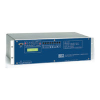
Schweitzer Engineering Laboratories SEL-352-2 Instruction Manual (444 pages)
BREAKER FAILURE RELAY; CONTROL RELAY; DATA RECORDER
Brand:
Schweitzer Engineering Laboratories
| Category:
Relays
| Size: 5.11 MB
Table of Contents
Table of Contents
11
Introduction and Specifications
13
Introduction
13
Instruction Manual Overview
13
Figure 1.1: Single-Phase Diagram of AC Inputs to the Relay
13
Relay Functions
15
Breaker Failure Detection
15
Figure 1.2: Functional Overview
15
Additional Features
16
Control Features
16
Data Recording
16
Model Options
17
Conventional Terminal Blocks
17
Plug-In Connectors (Connectorized )
17
SEL-352-1 Relay
17
SEL-352-2 Relay
17
Interface Boards
18
Signal Processing Specifications
18
Figure 1.3: Analog Filter Curve
18
General Specifications
19
Relay Element Specifications
22
Overcurrent Elements
22
Figure 1.4: 50FT Pickup Curves
23
Figure 1.5: 50FT Dropout Curves
23
Pickup/Dropout Curves
23
Figure 1.6: 50MN, 50LD, 50MD, 50N Pickup Curves
24
Figure 1.7: 50MN, 50LD, 50MD, 50N Dropout Curves
24
Synchronism Check Element
25
Voltage Elements
25
Breaker Resistor Thermal Elements
26
Current Unbalance Element
26
Overpower Elements
26
Settable Timers
26
Fixed Timers
27
Internal Logic Timers
27
Metering
28
Multiple Setting Groups
28
Data Recording Specifications
28
Breaker Monitor Reporting
28
Event Records
28
Serial Port Specifications
29
Table of Contents
31
Installation
33
Relay Mounting
33
Panel Mount
33
Rack Mount
33
Dimensions and Cutout
34
Rear-Panel Connections
39
Connectorized
39
Terminal Block
39
Connections
43
Current Transformer Inputs
43
Frame Ground
43
Optoisolated Inputs
43
Potential Transformer Input
43
Power Supply
43
Output Contacts
44
Communications Port
45
Clock Synchronization, IRIG-B
46
Plug-In Connectors (Connectorized Model 0352Xy)
46
Typical AC/DC Connections
48
Circuit Board Configuration
49
Accessing the Relay Circuit Boards
49
Main Board
50
Output Contact Jumpers
50
Password and Breaker Jumpers
52
Second ALARM Contact Jumper
52
Clock Battery
53
Condition of Acceptability for North American Product Safety Compliance
53
EIA-232 Serial Port Jumpers
53
Low-Level Analog Interface
53
Other Jumpers
53
Interface Board 1 (16 Outputs, 8 Inputs)
54
Optional Interface Boards
54
Optoisolated Inputs
54
Output Contacts
55
Interface Board 2 (12 Outputs, 8 Inputs)
57
Optoisolated Inputs
57
Output Contacts
57
Interface Board 4 (4 Outputs, 16 Inputs)
60
Optoisolated Inputs
60
Output Contacts
60
Interface Board 5 (8 Outputs, 8 Inputs)
62
Optoisolated Inputs
62
Output Contacts
62
Interface Board 6 (12 Outputs, 8 Inputs)
65
Table of Contents
69
Breaker Failure Relaying Overview
73
Breaker Logic
73
Introduction
73
Available AC Connections
75
Example Breaker Specifications
76
Fault Current Conditions
77
Application Description
77
Operating Characteristic
77
Subsidence Current Logic
78
Scheme 1 (Fault Current)
79
Scheme 2 (Fault Current)
82
Scheme 3 (Fault Current)
83
Scheme 4 (Fault Current)
84
Scheme 5 (Fault Current)
85
Setting Description
87
Fault Detector (50FT)
87
RMS Overcurrent (50RMS) (SEL-352-2 Relay)
87
Trip Inputs (TRIPA, TRIPB, TRIPC)
87
Fault Current Logic Enable (FTLOG)
88
Trip Timer Pickup Time (Ttpu)-Scheme 4
88
Trip Timer Dropout Time (Ttdo)-Scheme 1
89
Trip Timer Dropout Time (Ttdo)-Scheme 4
89
Setting Calculations
89
Fault Detector (50FT)
89
Fault Clearing Pickup Time (Fcpu)
90
Fault Logic Enable (FTLOG)
90
Load or Line-Charging Current Conditions
91
Application Description
91
Operating Characteristic
91
Scheme 1 (Load Current)
91
Scheme 2 (Load Current with 52A Backup)
92
Setting Description
92
Trip Inputs (TRIPA, TRIPB, TRIPC)
92
Breaker Status (52AA, 52AB, 52AC)
93
Load Detector (50LD)
93
Ground Current Detector (50N)
94
Load Current Logic Enable (LDLOG)
94
Load Current Timers (Lppu, Ldpu)-Schemes 1 and 2
94
Pending Failure and Breaker Failure (Appu, Afpu)-Scheme 2
95
Setting Calculations
95
Pending Failure and Breaker Failure (Lppu, Ldpu)
95
Thermal Protection of Close and Trip Resistors
96
Application Description
96
Operating Characteristic
96
Voltage Nulling
97
Setting Description
97
Breaker Status (52AA, 52AB, 52AC)
97
Close Signals (CLOSE, MCLOSE)
97
Trip Inputs (TRIPA, TRIPB, TRIPC)
97
Negative-Sequence Overvoltage (47Q)
98
Phase Overpower (37OP)
98
Thermal Model Voltage Threshold (87TH)
98
Voltage Nulling Delay (Vnpu)
98
Maximum Magnitude Nulling (Kmag)
99
Maximum Phase Error to Null (Kang)
99
Thermal Logic Enable (THLOG)
99
Close Failure (26CF)
100
Close Pending Failure (26CP)
100
Overpower Pickup (Oppu)
100
Trip Failure (26TF)
100
Trip Pending Failure (26TP)
100
Blown Potential Supervision (59L, 27D)
101
Cooling Time Constants (CRTC, TRTC)
101
Setting Calculations
101
Thermal Model of Trip and Close Resistors
101
Phase Overpower (37OP)
102
Thermal Model Voltage Threshold (87TH)
102
Close Resistor Energy
103
Overpower Pickup (Oppu)
103
Close Failure (26CF)
104
Close Pending Failure (26CP)
104
Cooling Time Constants (CRTC, TRTC)
104
Trip Failure (26TF)
104
Trip Pending Failure (26TP)
104
Trip Resistor Energy
104
Flashover Conditions
105
Application Description
105
Operating Characteristic
105
Scheme 1 (Flashover, Six Potential Transformers)
105
Scheme 2 (Flashover, Three Potential Transformers)
106
Setting Description
107
Breaker Close Signal (CLOSE, MCLOSE)
107
Breaker Status (52AA, 52AB, 52AC)
107
High Set Differential Voltage (87H)
107
Trip Inputs (TRIPA, TRIPB, TRIPC)
107
Flashover Differential (87FO)
108
Overvoltage (59H/59L)
108
Flashover Pending Failure (Fppu)
109
Flashover Scheme Selection (FOLOG)
109
Flashover Failure (Ffpu)
110
Load Detector (50LD)
110
Current Unbalance Protection
110
Application Description
110
Operating Characteristic
110
Setting Description
111
Breaker Close Signals (CLOSE, MCLOSE)
111
Close Input (Ucpu)
112
Phase Current Unbalance Enable (UBLOG)
112
Phase Current Unbalance Ratio (46UB)
112
Unbalance Pending Failure (Uppu)
112
Unbalance Breaker Failure (Ufpu)
113
Setting Calculations
113
Phase Current Unbalance Ratio (46UB)
113
Application Guideline
113
Loss-Of-Dielectric Detection
115
Application Description
115
Operating Characteristic
115
Setting Description
116
Dielectric Pressure Level Indicators (LOD1, LOD2, LODCT)
116
Loss-Of-Dielectric Logic Enable (DELOG)
116
Leak Timer (L2Pu)
117
Breaker Alarm Logic
117
Application Description
117
Operating Characteristic
117
Failed CB Trip Resistors Put in Service
118
52A Contradicts Voltage
119
Failed CB Close Resistors Put in Service
119
Breaker DID Not Close
120
Current While Open
120
Trip While Open
120
Current after MOD Trip
121
MOD Contradicts Current
121
Slow Trip
121
Potential Transformers Disagree
122
Slow Close
122
Table of Contents
123
Breaker Control Overview
125
Close Logic
125
Controlled Closing
125
Application Description
125
Operating Characteristic
125
Scheme 1 (Staggered Close)
125
Scheme 2 (Synchronism Checking, Point-On-Wave)
126
Synchronism Checking
127
Point-On-Wave
128
Setting Description
132
Breaker Close Signals (CLOSE, MCLOSE)
132
Live Line/Bus Voltage (59L)
132
Trip Inputs (TRIPA, TRIPB, TRIPC)
132
Close Dropout (Clsdo)
133
Controlled Closing Scheme Selection (CLSLOG)
133
Dead Line/Bus under Voltage (27D)
133
Maximum Control Close Angle (25AC)-Scheme 2
134
Maximum Slip Frequency for Control Close (25SC)-Scheme 2
134
Staggered Close Timer Pickups (Rcapu, Rcbpu, Rccpu)-Scheme 1
134
Maximum Slip Frequency for Manual Close (25SM)-Scheme 2
135
Synchronizing Phase (SYNCP)-Scheme 2
135
Controlled Close Output Timers (CLSA, CLSB, and CLSC)-Scheme 2
136
Point-On-Wave Timer Pickup (Pcapu, Pcbpu, Pccpu)-Scheme 2
136
Synchronism Timer Dropout (Syncdo)-Scheme 2
136
Zero-Crossing Timer Pickup (Zcapu, Zcbpu, Zccpu)-Scheme 2
136
Setting Calculation
137
Point-On-Wave Timer Pickup (Pcapu, Pcbpu, Pccpu)-Scheme 2
137
Zero-Crossing Timers Pickup (Zcapu, Zcbpu, Zccpu)-Scheme 2
138
Retripping
139
Application Description
139
Operating Characteristic
139
Scheme 1 (Instantaneous Retrip)
139
Scheme 2 (Delayed Retrip)
139
Setting Description
140
Load Detector (50LD)
140
Retrip Timer Pickup (Rtpu)
140
Retripping Scheme Selection (RTPLOG)
140
Trip Inputs (TRIPA, TRIPB, and TRIPC)
140
Lockout Relay Control
141
Application Description
141
Example 1
141
Example 2
141
Operating Characteristic
141
Scheme 1 (no MOD Trip)
142
Scheme 2 (MOD Trip Used)
143
Setting Description
144
Breaker Failure Trip Mask (M86T)
144
Motor-Operated Disconnect Input Status (MODST)-Scheme 2
144
MOD Operating Current (50MD)
145
Timer 2 (M2Pu)
145
Timer 3 (M3Pu)-Scheme 2
145
Trip and Reset Logic Scheme Selection (TRLOG)
145
Output Contact
146
Table of Contents
147
Control Logic
149
Relay Logic Overview
149
Signal Processing
149
Frequency Tracking Specification
149
Relay Word Bits and SEL OGIC ® Control Equations
150
Relay Word Bits
150
Control Equations
153
SEL OGIC Control Equation Analog Compares
154
Limitations of SEL OGIC Control Equations
155
SEL OGIC Control Equation Set a Example
155
SEL OGIC Control Equation Operators Example
156
Processing Order and Processing Interval
157
Fixed Analog Comparisons
158
Optoisolated Inputs
159
Input Assignment Variables
160
Modst
160
Lod
160
Multiple Setting Groups (SS1, SS2)
161
Trip
161
Close, Mclose
161
Local Control Switches (LB1-LB16)
161
Remote Control Switches (RB1-RB16)
162
Remote Bit Application
162
Remote Bit States Not Retained When Power Is Lost
163
Remote Bit States Retained When Settings Changed or Active Setting Group Changed
163
Sel Ogic Control Equation Seta
163
Timers (62T1A, 62T1B, and 62T1C)
163
Latch Control Switches
164
SEL OGIC Control Equation Variables
164
Sel Ogic Control Equation Setb
164
Timers (62T2A, 62T2B, 62T2C and 62T3A, 62T3B, 62T3C)
164
Latch Control Switches
165
SEL OGIC Control Equation Variables
165
Output Contacts
165
Rotating Default Display
165
LED Targeting Logic
166
EN Target LED
166
PF Target LED
167
86BFT Target LED
168
86RS Target LED
168
TRIP Target LED
169
CLOSE Target LED
169
52A Target LED
170
A, B, and C Target Leds
170
Table of Contents
173
Metering
175
Metering Calculations
175
Metering and Monitoring
175
Breaker Monitor
176
Header
177
Breaker Operations
177
Current
178
Date and Time
178
Electrical Operate Time
178
Energy
178
Mechanical Operate Time
178
Operation
178
Operation Summary
179
Average Operation Times
179
Last Operation Times
179
Number of Operations
179
Percent Wear (SEL-352-2 Relay)
179
Total Current
179
Total Energy
179
Breaker Alarms
181
Total Count
181
Clearing the Breaker Monitor Report
182
Preloading the Breaker Monitor Report (SEL 352-2 Relay)
182
Resetting the Thermal Monitor
182
Status Monitor
182
Channel Offset
183
Master Offset
183
Power Supply
183
Temperature
183
Ram
183
Flash ROM
183
Analog-To-Digital Converter
183
Critical RAM
184
Eeprom
184
I/O Boards
184
Self-Testing Alarms
185
Failures
185
Warnings
185
Table of Contents
187
Introduction
189
Setting the Relay
189
Additional Relay Settings
191
Group Settings (SET Command)
191
Nominal Breaker Close Time (Tclose)
191
Nominal Breaker Trip Time (Topen)
191
Relay Identification (RELID)
191
Slow Trip Alarm (Slowtr)
191
Terminal Identification (TRMID)
191
Current Transformer Ratio (CTR)
192
Slow Close Alarm (Slowcl)
192
X-Side Potential Transformer Ratio (XPTR)
192
Y-Side Potential Transformer Ratio (YPTR)
192
Mask for Event Reporting (MER)
193
Global Settings (SET G Command)
193
Date Format (DATE_F)
193
Settings Descriptions
193
Control Equations
199
Fault Current Protection Scheme 1
206
Fault Current Protection Scheme 2
207
Fault Current Protection Scheme 3
207
Fault Current Protection Scheme 4
208
Fault Current Protection Scheme 5
208
Load Current Protection Scheme 1
209
Load Current Protection Scheme 2
209
Thermal Protection of Trip and Close Resistors
210
Flashover Protection Scheme 1
210
Flashover Protection Scheme 2
211
Unbalanced Current Protection
211
Loss-Of-Dielectric Detection
212
Controlled Closing Scheme 1 (Staggered Closing)
212
Controlled Closing Scheme 2 (Point-On-Wave Closing)
213
Retripping Scheme 1
213
Retripping Scheme 2
214
Lockout Relay Control Scheme 1 (no MOD Trip)
214
Lockout Relay Control Scheme 2 (MOD Tripping)
215
Ogic
199
Settings Sheets
215
Table of Contents
245
Establish Communication
247
Software
247
Cables
247
SEL-352 Relay to Computer
250
SEL-352 Relay to Modem
250
Relay to SEL-2020 or SEL-2030
251
Introduction
247
Serial Port Communications and Commands
247
Communications Protocol
252
Hardware Protocol
252
Software Protocol
253
Sel Ascii
253
SEL Compressed ASCII Protocol
254
SEL Distributed Network Protocol (SEL-352-2 Relay Only)
254
SEL Distributed Port Switch Protocol
254
SEL Fast Meter Protocol
254
SEL Fast Operate Protocol
254
Automatic Messages
255
Group Switch Message
255
Startup Message
255
Status Report
255
Summary Event Report
256
Access Levels
256
Access Level 0
257
Access Level 1
257
Access Level B (Breaker Level)
257
Access Level 2
258
Command Definitions
259
2AC (Access Level 2)
259
ACC (Access Level 1)
259
BAC (Breaker Access Level)
260
BRE (Breaker Report)
260
BRE C (Clear Breaker Report)
261
BRE S (Breaker Report Summary)
261
BRE W (Preload Breaker Wear Data) (SEL-352-2 Relay)
262
CAL (Calibration Access Level)
263
CEVE (Compressed Event)
263
CLO (Close)
263
CON N (Control Rbn)
264
COP M N (Copy Settings)
264
DAT (Date)
265
EVE (Event Reports)
265
GRO (Setting Group)
267
HEA (Resistor Heat Report)
267
HEA C (Clear Resistor Heating)
268
HIS (History of Events)
268
HIS C (Clear History and Events)
269
INI (Initialize I/O)
269
IRI (IRIG-B Synchronization)
272
MET (Metering Report)
272
OPE (Open)
272
PAS (Passwords)
273
PUL N (Pulse)
275
QUI (Quit)
275
R_S (Restore Factory Default Settings)
275
SER (Sequential Events Records)
276
SER C (Clear Sequential Events Records)
276
SET (Edit Settings)
277
SET G (Edit Global Settings)
278
SET P (Edit Port Settings)
279
SET R (Edit Report Settings)
279
Note: Make Sequential Events Recorder (SER) Settings with Care
280
SET T (Edit Display Text Settings)
280
SHO (Show Settings)
280
SHO G (Show Global Settings)
282
SHO P (Show Port Settings)
282
SHO R (Show Report Settings)
283
SHO T (Show Display Text Settings)
284
STA (Status Report)
285
TAR (Show Relay Word Targets)
285
TAR F N (Show Relay Word Targets on Front Panel)
286
TAR R (Reset Targets)
287
TIM (Time)
287
TRI (Trigger an Event)
287
Main Board Jumpers
288
Table of Contents
291
Front-Panel Interface
293
Front-Panel Operation
293
Time-Out
293
Displays
294
Local Bits (LB1-LB16)
294
Display Points (DP1-DP16)
296
Target Leds
296
Password Access
296
Pushbuttons
297
Target Reset
297
Meter
297
Events
297
Status
297
Other
297
Set
298
Cntrl
298
Group
298
Cancel
299
Select
299
Arrows
299
Exit
299
Section 10: Event Reports and Ser
303
Data Recording Settings
305
Global Settings (SET G Command)
305
Ler
305
Pre
305
Report Settings (SET R Command)
305
Alias1-Alias20
305
Label
306
Port Settings (SET P Command)
306
Auto
306
Introduction
305
Section 10: Event Reports and Ser
305
Event Reports (EVE)
306
Event Report Triggering
307
Relay Word Bit 86BFT
307
Relay Word Bit MER
307
TRIGGER Command
308
Event Report Setup
308
Retrieving Event Reports
308
Event Report Description
310
Data Columns
312
Heading
312
Event Type
316
Frequency Tracking
317
Voltage Nulling Factor
317
History of Event Reports
317
Clearing Event Report Buffer
317
Sequential Events Recorder (SER) Report
318
SER Report Row Triggering
318
SER Report Trigger Settings
318
Retrieving SER Report
318
Clearing the SER Report
319
SER Report Headings
319
SER Report Column Definitions
319
Date and Time
320
Element
320
State
320
Section 11: Testing and Troubleshooting
321
Section 11: Testing and Troubleshooting
323
Test Procedures
323
Test Aids Provided by the Relay
323
Test Methods
323
Target LED Illumination
323
Output Contact Assertion
324
Sequential Events Recorder (SER)
324
Low-Level Test Interface
324
Initial Checkout
325
Equipment Required
325
Checkout Procedure
325
Full Functional Test
333
Equipment Required
333
What Should be Tested
333
Setting Test
333
Meter Test
334
Ground Overcurrent Element Test
335
Phase Overcurrent Element Tests
335
Phase Voltage Element Tests
336
Phase Overpower Element Test
337
Differential Voltage Element Tests
338
Synchronism Checking Element Tests
338
Fault Current Breaker Failure, Scheme 1 Logic Test
339
Fault Current Breaker Failure, Scheme 2 Logic Test
341
Fault Current Breaker Failure, Scheme 3 Logic Test
341
Fault Current Breaker Failure, Scheme 4 Logic Test
343
Fault Current Breaker Failure, Scheme 5 Logic Test
344
Load Current Breaker Failure, Scheme 1 Logic Test
345
Load Current Breaker Failure, Scheme 2 Logic Test
346
Circuit Breaker Close Resistor Thermal Failure Logic Test
347
Voltage Nulling Logic Test
349
Loss-Of-Dielectric Logic Test
354
Staggered Close Logic Test
355
Point-On-Wave Close Logic Test
356
Synchronism Close Logic Test
358
IRIG-B Time-Code Input Test
363
Power Supply Voltages Test
363
Serial Ports Test
363
Calibration
364
Inspection Procedure
364
Troubleshooting Table
364
All Front-Panel Leds Dark
364
System Does Not Respond to Commands
364
No Prompting Message Issued to Terminal Upon Power up
365
SEL BOOT " on LCD Display and Serial Port Warning to Remove Jumper (at Power-Up)
365
System Does Not Respond to Faults
365
Terminal Displays Meaningless Characters
365
Time Command Displays the same Time for Successive Commands
365
Tripping Output Relay Remains Closed Following Fault
365
Alarm Contacts Closed
366
Self-Test Failure: A/D Converter
366
Self-Test Failure: CR_RAM
366
Self-Test Failure: CR_RAM, EEPROM, and IO_BRD
366
Self-Test Failure: IO_BRD
366
Self-Test Failure: Offset
366
Self-Test Failure: RAM
366
Self-Test Failure: ROM
366
Self-Test Failure: Temp after R_S Command
367
Factory Assistance
367
Appendix D: Configuration, Fast Meter, and Fast Operate Commands
385
Appendix D: Configuration, Fast Meter, and Fast Operate Commands
387
Message Lists
387
Binary Message List
387
ASCII Configuration Message List
387
Message Definitions
388
A5C0 Relay Definition Block
388
A5C1 Fast Meter Configuration Block
388
A5D1 Fast Meter Data Block
390
A5B9 Fast Meter Status Acknowledge Message
390
A5E3 Fast Operate Breaker Control
393
ID Command Response
393
DNA Command Response
393
BNA Command Response
394
Table of Contents
421
Appendix G: Distributed Network Protocol (Dnp)
423
Configuration
423
Overview
423
Data Access Method
424
Data-Link Operation
424
Device Profile
425
Object Table
428
Data Map
430
Relay Summary Event Data
437
Point Remapping
438
Introduction
438
Inputs
438
Modem Support
440
Virtual Terminal
440
Advertisement
Advertisement
Related Products
Schweitzer Engineering Laboratories SEL-352-1
Schweitzer Engineering Laboratories SEL-351S
Schweitzer Engineering Laboratories SEL-351-1
Schweitzer Engineering Laboratories SEL-351-0
Schweitzer Engineering Laboratories SEL-351-3
Schweitzer Engineering Laboratories SEL-351-2
Schweitzer Engineering Laboratories SEL-351-4
Schweitzer Engineering Laboratories SEL-351-5
Schweitzer Engineering Laboratories SEL-351-6
Schweitzer Engineering Laboratories SEL-351-7
Schweitzer Engineering Laboratories Categories
Relays
Computer Hardware
Transceiver
Protection Device
Measuring Instruments
More Schweitzer Engineering Laboratories Manuals
Login
Sign In
OR
Sign in with Facebook
Sign in with Google
Upload manual
Upload from disk
Upload from URL