Sign In
Upload
Manuals
Brands
Schweitzer Engineering Laboratories Manuals
Protection Device
SEL-311L
Schweitzer Engineering Laboratories SEL-311L Manuals
Manuals and User Guides for Schweitzer Engineering Laboratories SEL-311L. We have
1
Schweitzer Engineering Laboratories SEL-311L manual available for free PDF download: Instruction Manual
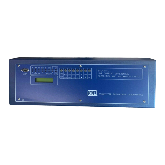
Schweitzer Engineering Laboratories SEL-311L Instruction Manual (734 pages)
LINE CURRENT DIFFERENTIAL PROTECTION AND AUTOMATION SYSTEM
Brand:
Schweitzer Engineering Laboratories
| Category:
Protection Device
| Size: 7.25 MB
Table of Contents
Table of Contents
7
Introduction and Specifications
9
SEL-311L Relay Models
9
Instruction Manual Sections Overview
10
Applications
13
Figure 1.1: Typical Two-Terminal Application with Hot Standby Channel and Tapped Load
13
Figure 1.2: Typical Two-Terminal Application with Voltage Inputs
14
Figure 1.3: Typical Three-Terminal Application with Optional Third Communications Channel
14
AC/DC Connections
15
Figure 1.4: SEL-311L Relay Inputs and Outputs
15
Figure 1.5: SEL-311L Relay Communications Interfaces
16
Figure 1.6: SEL-311L Relay Communications Connections Examples
17
Relay Specifications
18
General Specifications
18
Processing Specifications
21
Relay Element Settings Ranges and Accuracies
22
Table of Contents
27
Installation
29
Relay Mounting
29
Front- and Rear-Panel Diagrams
31
Making Rear-Panel Connections
35
Current Transformer Inputs
35
Optoisolated Inputs
35
Output Contacts
35
Potential Transformer Inputs (Optional Connections)
35
Power Supply
35
IRIG-B Time-Code Input
36
Serial Ports (1, 2, 3, and F)
36
Line Current Differential Communications Channel Interfaces
37
Table 2.1: EIA-232 Communications Cables to Connect the SEL-311L Relay to Other Devices
37
Table 2.2: SEL-311L Relay Line Current Differential Electrical Interface Cable Application
40
Circuit Board Connections
44
Accessing the Relay Circuit Boards
44
Extra Alarm" Output Contact Control Jumper
47
Output Contact Jumpers
47
Table 2.4: Move Jumper JMP23 to Select Extra Alarm
48
EIA-232 Multifunction Serial Port Voltage Jumpers
49
Password and Breaker Jumpers
49
Table 2.5: Password and Breaker Jumper Operation
49
Table 2.6: EIA-232 Serial Port Voltage Jumper Positions for Standard Relay Shipments
49
Clock Battery
50
Table of Contents
51
Current Differential Elements
55
Theory of Operation (Patented)
56
Setting the Restraint Region and Supervision Elements
57
Factory Settings Give Excellent Security During External Faults
64
SEL-5601 Produces Alpha Plane Plots
65
Settings Related to 87L Elements
68
Three-Terminal Protection with the SEL-311L
72
Differential Element Settings and Specifications
77
Line Current Differential, Distance, Out-Of-Step, Overcurrent, Voltage, Synchronism Check, and Frequency Elements
55
Distance Elements
85
Mho Phase Distance Elements
85
Ground Distance Elements
93
Additional Distance Element Supervision
99
Zone 1 Extension
100
Zone Time Delay Elements
100
Out-Of-Step (OOS) Characteristics
102
Use SEL-321 Relay Application Guides for the SEL-311L Relay
102
Instantaneous/Definite-Time Overcurrent Elements
106
Phase Instantaneous/Definite-Time Overcurrent Elements
106
Residual Ground Instantaneous/Definite-Time Overcurrent Elements
109
Negative-Sequence Instantaneous/Definite-Time Overcurrent Elements
112
Overcurrent Protection
106
Time-Overcurrent Elements
115
Phase Time-Overcurrent Elements
115
Residual Ground Time-Overcurrent Element
119
Negative-Sequence Time-Overcurrent Element
121
Voltage Elements
122
Voltage Values
122
Voltage Element Settings
123
Voltage Element Operation
127
Synchronism Check Elements
128
Fixed Angle Synchronism Check
128
Dynamic Synchronism Check
128
Synchronism Check Elements Settings
129
Synchronism Check Elements Voltage Inputs
132
Synchronism Check Elements Operation
132
Synchronism Check Applications for Automatic Reclosing and Manual Closing
138
Frequency Elements
139
Frequency Element Settings
139
Frequency Element Operation
142
Frequency Element Uses
143
Table of Contents
145
Introduction
147
Setting ELOP = y or Y1
148
Setting ELOP = N
149
Loss-Of-Potential, Ccvt Transient Detection, Load-Encroachment, and Directional Element Logic
147
CCVT Transient Detection Logic
149
Load-Encroachment Logic
150
Settings Ranges
152
Load-Encroachment Setting Example
152
Convert Power Factors to Equivalent Load Angles
153
Use SEL-321 Relay Application Guide for the SEL-311L Relay
154
Directional Control for Ground Distance and Residual Ground Overcurrent Elements
155
Directional Element Enables
156
Best Choice Ground Directional Logic
156
Directional Elements
156
Directional Element Routing
157
Table of Contents
175
Introduction
177
Line Current Differential Trips
177
High-Speed 87L Tripping
177
Tripping Via SEL OGIC
177
87L High-Speed Direct Transfer Tripping
177
87L Tripping Qualified by the Local Disturbance Detector
178
Trip and Target Logic
177
Backup Protection Trips
181
Set Trip
183
Unlatch Trip
184
Factory Settings Example (Using Setting TR)
184
Additional Settings Examples
185
Program an Output Contact for Tripping
186
Switch-Onto-Fault (SOTF) Trip Logic
186
Three-Pole Open Logic
187
Circuit Breaker Operated Switch-Onto-Fault Logic
188
Close Bus Operated Switch-Onto-Fault Logic
189
Switch-Onto-Fault Logic Output (SOTFE)
189
Switch-Onto-Fault Trip Logic Trip Setting (TRSOTF)
189
Communications-Assisted Trip Logic-General Overview
190
Enable Setting ECOMM
191
Trip Setting TRCOMM
191
Trip Settings TRSOTF and TR
192
Trip Setting DTT
192
Use Existing SEL-321 Relay Application Guides for the SEL-311L Relay
192
Permissive Overreaching Transfer Trip (POTT) Logic
193
Use Existing SEL-321 Relay POTT Application Guide for the SEL-311L Relay
193
External Inputs
193
Timer Settings
194
Logic Outputs
194
Weak-Infeed Logic and Settings
195
SEL-311L Relay Weak-Infeed Logic
195
Variations for Permissive Underreaching Transfer Trip (PUTT) Scheme
198
Installation Variations
198
Directional Comparison Unblocking (DCUB) Logic
200
Use Existing SEL-321 Relay DCUB Application Guide for the SEL-311L Relay
200
External Inputs
200
Timer Settings
201
Logic Outputs
202
Installation Variations
204
Directional Comparison Blocking (DCB) Logic
206
Use Existing SEL-321 Relay DCB Application Guide for the SEL-311L Relay
206
Table of Contents
217
Close and Reclose Logic
219
Close Logic
219
Set Close
220
Unlatch Close
221
Factory Settings Example
221
Defeat the Close Logic
222
Circuit Breaker Status
222
Program an Output Contact for Closing
222
Overview
219
Reclose Supervision Logic
223
Settings and General Operation
225
Settings Example
227
Reclosing Relay
229
Reclosing Relay States and General Operation
230
Reclosing Relay States after a Settings or Setting Group Change
231
Defeat the Reclosing Relay
232
Reclosing Relay Timer Settings
233
Reclosing Relay Shot Counter
236
Ogic
236
Control Equation Settings Overview
236
Reclose Initiate and Reclose Initiate Supervision Settings (79RI and 79RIS, Respectively)
237
Drive-To-Lockout and Drive-To-Last Shot Settings (79DTL and 79DLS, Respectively)
239
Skip Shot and Stall Open Interval Timing Settings (79SKP and 79STL, Respectively)
241
Block Reset Timing Setting (79BRS)
243
Sequence Coordination Setting (79SEQ)
244
Table of Contents
249
Inputs, Outputs, Timers, and Other Control Logic
253
Optoisolated Inputs
253
Input Debounce Timers
254
Input Functions
255
Settings Example 1
255
Local Control Switches
257
Local Control Switch Types
258
Settings Examples
260
Additional Local Control Switch Application Ideas
261
Local Control Switch States Retained
261
Remote Control Switches
262
Remote Bit Application Ideas
263
Remote Bit States Not Retained When Power Is Lost
263
Changed
263
Latch Control Switches
263
Latch Control Switch Application Ideas
265
Reclosing Relay Enable/Disable Setting Example
265
Latch Control Switch States Retained
269
Reset Latch Bits for Active Setting Group Change
269
Note: Make Latch Control Switch Settings with Care
270
Active Setting Group Indication
272
Selecting the Active Setting Group
272
Operation of SEL OGIC
273
Control Equation Settings SS1 through SS6
273
Operation of Serial Port GROUP Command and Front-Panel GROUP Pushbutton
273
Relay Disabled Momentarily During Active Setting Group Change
274
Active Setting Group Switching Example 1
274
Active Setting Group Switching Example 2
277
Active Setting Group Retained
280
Note: Make Active Setting Group Switching Settings with Care
281
Sel Ogic
281
Settings Example
282
Additional Settings Example 1
283
Additional Settings Example 2
284
Timers Reset When Power Is Lost, Settings Are Changed, or Active Setting Group Is Changed
284
Output Contacts
285
Operation of Output Contacts
285
High-Speed 87L Tripping-Example 1
289
High-Speed 87L Tripping with Backup Protection Tripping-Example 2
289
Table of Contents
303
Breaker Monitor
305
Breaker Monitor Setting Example
308
Breaker Monitor Operation Example
311
Breaker Monitor Output
316
View or Reset Breaker Monitor Information
316
Determination of Relay-Initiated Trips and Externally Initiated Trips
317
Breaker Monitor and Metering Functions
305
Introduction
305
Station DC Battery Monitor
319
DC Under- and Overvoltage Elements
319
Create Desired Logic for DC Under- and Overvoltage Alarming
319
Additional Application
321
View Station DC Battery Voltage
322
Analyze Station DC Battery Voltage
322
Operation of Station DC Battery Monitor When AC Voltage Is Powering the Relay
323
Instantaneous Metering
324
Metering
324
Local Demand Metering
326
Demand Meter Settings
330
Demand Current Logic Output Application-Raise Pickup for Unbalance Current
331
View or Reset Demand Metering Information
334
Demand Metering Updating and Storage
334
Local Energy Metering
334
View or Reset Energy Metering Information
334
Energy Metering Updating and Storage
335
View or Reset Maximum/Minimum Metering Information
335
Maximum/Minimum Metering Updating and Storage
336
Section 10: Line Current Differential
425
Current Differential Communications, Channel Configuration, and Channel Monitor
427
Channel Configuration Settings
427
Types
432
Availability and Delay Monitor Drive Front Panel LED 87CH FAIL
432
Rear Panel TX/RX LED
432
Loopback, End-To-End, and Back-To-Back Testing with the TST Command
436
87L COMM Report
437
Irig-B
439
SEL-311L to Computer
440
SEL-311L to Starcomm Modem, 5 VDC Powered
442
SEL-311L to Modem or Other DCE
442
Introduction
427
Section 10: Line Current Differential
427
Communications and Serial Port
427
Communications and Commands
427
Communications Protocols
443
Hardware Protocol
443
Software Protocols
443
SEL-DTA Protocol
446
Using and Changing SEL-311L Relay Passwords
446
Serial Port Access Levels
448
Access Level 0
448
Access Level 1
448
Access Level B
449
Access Level 2
451
Command Explanations
452
Access Level 0 Commands
452
Access Level 1 Commands
454
Access Level B Commands
474
Access Level 2 Commands
477
SEL-311L Relay Command Summary
481
Table of Contents
485
Front-Panel Interface
487
Front-Panel Pushbutton Operation
487
Overview
487
Primary Functions
487
Front-Panel Password Security
488
Secondary Functions
489
Introduction
487
Functions Unique to the Front-Panel Interface
491
Reclosing Relay Shot Counter Screen
491
Reclosing Relay Shot Counter Screen Operation
492
Local Control
493
View Local Control (with Example Settings)
494
Operate Local Control (with Example Settings)
495
Local Control State Retained When Relay Deenergized
496
Rotating Default Display
497
Scroll Lock Control of Front Panel LCD
500
Stop Scrolling (Lock)
500
Restart Scrolling (Unlock)
500
Single Step
500
Exit
501
Cancel
501
Additional Rotating Default Display Example
501
Section 12: Standard Event Reports and Ser
503
Introduction
505
Section 12: Standard Event Reports and Ser
505
Standard 15/30/60-Cycle Event Reports
505
Event Report Length (Settings LER and PRE)
505
Standard Event Report Triggering
506
Event Summary
507
Retrieving Full-Length Standard Event Reports
510
Compressed ASCII Event Reports
512
Filtered and Unfiltered Event Reports
513
Clearing Standard Event Report Buffer
514
Standard Event Report Column Definitions for Backup Protection
514
Example Standard 15-Cycle Event Report (Backup Protection)
540
Example Standard 15-Cycle Event Report (Differential Protection)
540
Sequential Events Recorder (SER) Report
547
SER Triggering
547
Making SER Trigger Settings
547
Retrieving SER Reports
548
Clearing SER Report
549
Example Sequential Events Recorder (SER) Report
549
Table of Contents
553
Introduction
555
Testing Philosophy
555
Acceptance Testing
555
Commissioning Testing
555
Maintenance Testing
556
Test Methods
559
Introduction
560
Protection)
568
Testing, Troubleshooting, and Commissioning
555
Relay Troubleshooting
570
Inspection Procedure
570
Troubleshooting Procedure
570
Factory Assistance
573
Relay Calibration
573
Section 14: Application Settings for Sel-311L Relays
575
Section 14: Application Settings for Sel-311L Relays
577
Introduction
577
Application Settings
579
Application Settings
599
Application Settings
625
Appendix B: Firmware Upgrade Instructions/Appendix D: Configuration, Fast Meter, and Fast
651
Appendix A: Firmware Versions
657
Appendix B: Firmware Upgrade Instructions
657
Upgrade Procedure
657
Appendix C: Sel Distributed Port Switch Protocol
657
Settings
657
Operation
663
Appendix D: Configuration, Fast Meter, and Fast
665
Operate Commands
665
Introduction
665
Message Lists
665
Message Definitions
666
ID Message
675
DNA Message
676
BNA Message
678
SNS Message
678
Appendix I: Mirrored Bits ™ Communications
717
Message Decoding and Integrity Checks
717
Message Transmission
717
Operation
717
Overview
717
Synchronization
718
Channel Monitoring
719
Loopback Testing
719
Mirrored Bits
719
Settings
720
Appendix J: Example Calculations for 87L Settings
723
87LANG Setting Considerations
723
Calculating I AR al
724
Calculating I for Ground Faults
725
Summary
726
Example 1: 500 Kv OH Transmission Line: 100 Miles of Single 1113 MCM Conductor
727
Example 2: 15 Kv Underground Cable: 5 Miles
727
Line Charging Current Calculation Examples
727
Ground Fault Resistance Coverage with 87L2P = 0.5 a
728
Appendix K: Sel-5030 Ac Sel Erator
729
AC SEL ERATOR System Requirements
729
Introduction
729
Installation
730
Starting AC SEL ERATOR
730
Advertisement
Advertisement
Related Products
Schweitzer Engineering Laboratories SEL-311B
Schweitzer Engineering Laboratories SEL-311A
Schweitzer Engineering Laboratories SEL-311C
Schweitzer Engineering Laboratories SEL-352-2
Schweitzer Engineering Laboratories SEL-387-0
Schweitzer Engineering Laboratories SEL-351-1
Schweitzer Engineering Laboratories SEL-351-0
Schweitzer Engineering Laboratories SEL-351-2
Schweitzer Engineering Laboratories SEL-351-4
Schweitzer Engineering Laboratories SEL-300G
Schweitzer Engineering Laboratories Categories
Relays
Computer Hardware
Transceiver
Protection Device
Measuring Instruments
More Schweitzer Engineering Laboratories Manuals
Login
Sign In
OR
Sign in with Facebook
Sign in with Google
Upload manual
Upload from disk
Upload from URL