Sign In
Upload
Manuals
Brands
Rohde & Schwarz Manuals
Measuring Instruments
FSW13
Rohde & Schwarz FSW13 Manuals
Manuals and User Guides for Rohde & Schwarz FSW13. We have
5
Rohde & Schwarz FSW13 manuals available for free PDF download: User Manual, Getting Started
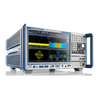
Rohde & Schwarz FSW13 User Manual (1150 pages)
Signal and Spectrum Analyzer
Brand:
Rohde & Schwarz
| Category:
Measuring Instruments
| Size: 23.55 MB
Table of Contents
Table of Contents
3
About this Manual
15
Preface
15
Documentation Overview
16
Conventions Used in the Documentation
17
Typographical Conventions
17
Conventions for Procedure Descriptions
18
Welcome to the R&S FSW
19
Getting Started
20
Preparing for Use
20
Putting into Operation
20
Windows Operating System
27
Connecting USB Devices
30
Connecting an External Monitor
31
Setting up a Network (LAN) Connection
33
Configuring the Initial Instrument Settings
37
Protecting Data Using the Secure User Mode
37
Instrument Tour
39
Front Panel View
39
Rear Panel View
52
Trying out the Instrument
58
Measuring a Basic Signal
59
Displaying a Spectrogram
61
Activating Additional Measurement Channels
62
Performing Sequential Measurements
65
Setting and Moving a Marker
66
Displaying a Marker Peak List
67
Zooming into the Display
68
Saving Settings
71
Printing and Saving Results
73
Operating the Instrument
73
Understanding the Display Information
74
Accessing the Functionality
83
Changing the Focus
83
Entering Data
83
Displaying Results
85
Getting Help
92
Remote Control
94
Applications and Operating Modes
96
R&S Multiview
97
Available Applications
98
Selecting the Operating Mode
103
Starting an Application
104
Running a Sequence of Measurements
105
The Sequencer Concept
105
Sequencer Settings
107
How to Set up the Sequencer
108
Measurements
110
Available Measurement Functions
110
Frequency Sweep
111
Chapter 6 .1, "Configuration Overview" ,On Page 312
111
Frequency Sweep
111
C/N, C/No
112
Ch Power ACLR
112
Zero Span
112
Apd
113
Obw
113
Spectrum Emission Mask
113
Spurious Emissions
113
AM Mod Depth
114
Ccdf
114
Harmonic Distortion
114
Time Domain Power
114
Toi
114
Basic Measurements
115
How to Perform a Basic Sweep Measurement
115
All Functions off
115
Emi
115
Marker Functions
115
Measurement Examples - Measuring a Sinusoidal Signal
116
Measurement Example - Measuring Levels at Low S/N Ratios
119
Measurement Examples - Measuring Signal Spectra with Multiple Signals
123
Measurement Examples in Zero Span
129
5.3 Channel Power and Adjacent-Channel Power (Aclr) Measurement
135
Channel Power and Adjacent-Channel Power (ACLR) Measurement
135
About Channel Power Measurements
136
Channel Power Results
136
Channel Power Basics
138
Channel Power Configuration
148
MSR ACLR Configuration
158
How to Perform Channel Power Measurements
172
Measurement Examples
176
Optimizing and Troubleshooting the Measurement
182
Reference: Predefined CP/ACLR Standards
183
Carrier-To-Noise Measurements
184
About the Measurement
184
Carrier-To-Noise Results
185
Carrier-To-Noise Configuration
186
How to Determine the Carrier-To-Noise Ratio
187
Occupied Bandwidth Measurement (OBW)
188
About the Measurement
188
OBW Results
190
OBW Configuration
191
How to Determine the Occupied Bandwidth
193
Measurement Example
193
Spectrum Emission Mask (SEM) Measurement
194
About the Measurement
194
SEM Results
195
Typical Applications
195
SEM Basics
198
SEM Configuration
208
Sweep List
209
Multi-SEM (Sub Block) Settings
215
Reference Range
216
Power Classes
218
MSR Settings
219
Standard Files
222
List Evaluation (Results Configuration)
224
How to Perform a Spectrum Emission Mask Measurement
225
Measurement Example: Multi-SEM Measurement
230
Reference: SEM File Descriptions
231
Spurious Emissions Measurement
238
About the Measurement
238
Spurious Emissions Measurement Results
239
Spurious Emissions Basics
240
Spurious Emissions Measurement Configuration
242
Table of Contents
243
Detector
244
Rbw
244
Ref. Level
244
Sweep Time
244
Sweep Time Mode
244
Vbw
244
Preamp
245
RF Att. Mode
245
RF Attenuator
245
Stop after Sweep
245
Sweep Points
245
Transducer
245
Abs Limit Start/Stop
246
Delete Range
246
Insert Before/After Range
246
Limit Check
246
How to Perform a Spurious Emissions Measurement
248
Reference: ASCII Export File Format (Spurious)
249
5.8 Statistical Measurements (Apd, Ccdf)
251
About the Measurements
251
Statistical Measurements (APD, CCDF)
251
Typical Applications
251
APD and CCDF Results
252
APD and CCDF Basics - Gated Triggering
254
APD and CCDF Configuration
255
How to Perform an APD or CCDF Measurement
261
Examples
262
Optimizing and Troubleshooting the Measurement
265
Time Domain Power Measurement
265
About the Measurement
265
Time Domain Power Results
265
Time Domain Power Basics - Range Definition Using Limit Lines
266
Time Domain Power Configuration
267
How to Measure Powers in the Time Domain
268
Measurement Example
268
Harmonic Distortion Measurement
269
About the Measurement
270
Harmonic Distortion Basics
270
Harmonic Distortion Configuration
273
Harmonic Distortion Results
273
How to Determine the Harmonic Distortion
275
Third Order Intercept (TOI) Measurement
275
About the TOI Measurement
276
TOI Basics
276
TOI Results
280
TOI Configuration
281
How to Determine the Third Order Intercept
282
Measurement Example - Measuring the R&S Fsw's Intrinsic Intermodulation
283
AM Modulation Depth Measurement
285
About the Measurement
285
AM Modulation Depth Results
285
AM Modulation Depth Configuration
286
Optimizing and Troubleshooting the Measurement
287
About the EMI Measurement
288
How to Determine the am Modulation Depth
288
Electromagnetic Interference (EMI) Measurement (R&S FSW-K54)
288
EMI Measurement Results
289
5.13.3 Emi Measurement Basics
290
EMI Measurement Basics
290
Resolution Bandwidth and Filter Types
290
Detectors and Dwell Time
291
Frequency Resolution - Sweep Points and Scaling
294
Controlling V-Networks (LISN)
295
Using Transducer Factors
296
Initial Measurement - Peak Search
296
Final Measurement at the Marker Position
297
Limit Checks
298
5.13.4 Emi Measurement Configuration
299
Chapter 7.5.3.2, "Limit Line Settings and Functions", on Page 528 EMI Marker Configuration
299
EMI Measurement Configuration
299
Marker Position (X-Value)
299
Marker State
299
Selected Marker
299
Assigning the Marker to a Trace
300
Linking to Another Marker
300
Marker Type
300
Reference Marker
300
Final Test Detector
301
Select Marker
301
EMI Final Measurement Configuration
302
LISN Control Settings
304
EMI Result Analysis
306
How to Perform EMI Measurements
306
Measurement Example: Measuring Radio Frequency Interference
308
Optimizing and Troubleshooting EMI Measurements
310
Common Measurement Settings
312
Configuration Overview
312
Data Input and Output
314
Receiving Data Input and Providing Data Output
314
Input Source Settings
318
Power Sensors
321
External Generator Control (Option R&S FSW-B10)
331
Error and Status Messages
341
External Mixer (Option R&S FSW-B21)
358
Output Settings
381
Frequency and Span Configuration
384
Impact of the Frequency and Span Settings
385
Frequency and Span Settings
387
Chapter 9 .3.2, "Transducer Settings" ,On Page 571
299
Center Frequency/Span
388
Center Frequency
388
Span
388
Frequency Axis Scaling
389
Full Span
389
Start / Stop
389
Zero Span
389
Center Frequency Stepsize
390
Frequency Offset
390
How to Define the Frequency Range
391
Signal Tracking
391
Signal Tracking State
391
Tracking └ Tracking └ Trace
391
How to Move the Center Frequency through the Frequency Range
392
How to Keep the Center Frequency Stable
392
Amplitude and Vertical Axis Configuration
393
Impact of the Vertical Axis Settings
393
Amplitude Settings
395
Scaling the Y-Axis
399
How to Optimize the Amplitude Display
401
Bandwidth, Filter and Sweep Configuration
402
Impact of the Bandwidth, Filter and Sweep Settings
402
Bandwidth, Filter and Sweep Settings
408
Reference: List of Available RRC and Channel Filters
416
Trigger and Gate Configuration
418
Basics of Triggering and Gated Measurements
419
Trigger and Gate Settings
425
How to Configure a Triggered and Gated Measurement
434
Last Span
390
How to Output a Trigger Signal
436
Adjusting Settings Automatically
437
Common Analysis and Display Functions
440
Result Display Configuration
440
Basic Evaluation Methods
440
Laying out the Result Display with the Smartgrid
442
Zoomed Displays
447
Single Zoom Versus Multiple Zoom
447
Zoom Functions
448
How to Zoom into a Diagram
449
Trace Configuration
451
Basics on Setting up Traces
452
Trace Configuration
464
How to Configure Traces
477
Marker Usage
482
Basics on Markers and Marker Functions
483
Marker Configuration
493
Marker Function Configuration
507
How to Work with Markers
519
Measurement Example: Measuring Harmonics Using Marker Functions
522
Display and Limit Lines
523
Basics on Display Lines
524
Basics on Limit Lines
524
Settings and Functions for Display and Limit Lines
527
How to Work with Display and Limit Lines
534
Data Management
538
Restoring the Default Instrument Configuration (Preset)
538
Factory Default Configuration
539
Protecting Data Using the Secure User Mode
540
Storing and Recalling Instrument Settings and Measurement Data
542
Quick Save/Quick Recall
543
Configurable Storage and Recall
545
How to Save and Load Instrument Settings
551
Importing and Exporting Measurement Results for Evaluation
553
Import/Export Functions
554
How to Export Trace Data and Numerical Results
555
How to Export a Peak List
556
Reference: ASCII File Export Format
557
Creating Screenshots of Current Measurement Results and Settings
560
Print and Screenshot Settings
560
How to Store or Print Screenshots of the Display
564
General Instrument Setup
565
Basics on Alignment
565
Basics on Transducer Factors
566
General Instrument Settings
568
Reference Frequency Settings
568
Transducer Settings
571
Alignment Settings
576
System Configuration Settings
577
Service Functions
583
Display Settings
590
General Display Settings
591
Displayed Items
592
Display Theme and Colors
596
External Monitor Settings
600
How to Configure the Basic Instrument Settings
601
How to Align the Instrument
602
How to Perform a Self Test
602
How to Align the Touchscreen
603
How to Install an R&S FSW Option
603
How to Update the Instrument Firmware
603
How to Configure the Transducer
604
How to Configure the Colors for Display and Printing
606
How to Work with the Soft Front Panels
607
Network and Remote Operation
609
Remote Control Basics
609
Remote Control Interfaces and Protocols
609
SCPI (Standard Commands for Programmable Instruments)
614
VISA Libraries
614
Messages
615
SCPI Command Structure
616
Command Sequence and Synchronization
624
Status Reporting System
627
General Programming Recommendations
644
GPIB Languages
645
The IECWIN Tool
647
Network and Remote Control Settings
648
General Network Settings
649
GPIB Settings
650
Compatibility Settings
652
LXI Settings
655
How to Set up a Network and Remote Control
657
How to Configure a Network
658
How to Log on to the Network
664
How to Operate the Instrument Without a Network
664
How to Share Directories (Only with Microsoft Networks)
666
How to Set up Remote Desktop
667
How to Start a Remote Control Session from a PC
674
How to Return to Manual Operation
675
Remote Commands
676
Conventions Used in SCPI Command Descriptions
676
Common Suffixes
677
Common Commands
677
Selecting the Operating Mode and Application
682
Selecting the Mode and Applications
682
Performing a Sequence of Measurements
687
Programming Example: Performing a Sequence of Measurements
690
Configuring and Performing Measurements
692
Performing Measurements
692
Configuring Power Measurements
695
Measuring the Channel Power and ACLR
700
Measuring the Carrier-To-Noise Ratio
726
Measuring the Occupied Bandwidth
727
Measuring the Spectrum Emission Mask
729
Measuring Spurious Emissions
765
Analyzing Statistics (APD, CCDF)
778
Measuring the Time Domain Power
787
Measuring the Harmonic Distortion
795
Measuring the Third Order Intercept Point
799
Measuring the am Modulation Depth
801
Remote Commands for EMI Measurements
803
List Evaluations
811
Measuring the Pulse Power
816
Configuring the Result Display
821
General Window Commands
821
Working with Windows in the Display
822
Examples: Configuring the Result Display
827
Setting Basic Measurement Parameters
830
Defining the Frequency and Span
830
Configuring Bandwidth and Sweep Settings
836
Configuring the Vertical Axis (Amplitude, Scaling)
844
Configuring Triggered and Gated Measurements
850
Adjusting Settings Automatically
860
Configuring the Data Input and Output
864
Analyzing Measurements (Basics)
907
Zooming into the Display
907
Configuring the Trace Display and Retrieving Trace Data
909
Working with Markers
928
Configuring Display and Limit Lines
975
Managing Settings and Results
990
General Data Storage and Loading Commands
991
Selecting the Items to Store
997
Storing and Loading Instrument Settings
1000
Storing or Printing Screenshots
1005
Storing Measurement Results
1011
Examples: Managing Data
1015
Configuring the R&S FSW
1018
Configuring the Reference Frequency
1018
Calibration and Temperature Checks
1022
Working with Transducers
1025
Customizing the Screen Layout
1028
Configuring the Network and Remote Control
1035
Checking the System Configuration
1038
Using Service Functions
1043
Using the Status Register
1044
General Status Register Commands
1045
Reading out the Condition Part
1045
Reading out the Event Part
1046
Controlling the Enable Part
1047
Controlling the Negative Transition Part
1047
Controlling the Positive Transition Part
1048
Commands for Remote Instrument Operation
1048
Emulating Other Instruments' Commands
1049
Setting up Instrument Emulation
1049
Reference: GPIB Commands of Emulated HP Models
1053
Reference: Command Set of Emulated PSA Models
1081
Commands for Compatibility
1085
Programming Examples
1087
Programming Example: Performing a Basic Frequency Sweep
1088
Service Request
1090
Maintenance
1099
Optimizing and Troubleshooting
1100
Error Information
1100
Error Messages in Remote Control Mode
1102
Troubleshooting Remote Operation
1103
Improving Averaging Results
1104
Minimizing the Measurement Duration
1104
Miscellaneous Troubleshooting Hints
1105
Obtaining Technical Support
1105
List of Remote Commands (Base Unit)
1107
Index
1124
Advertisement
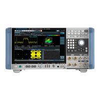
Rohde & Schwarz FSW13 User Manual (371 pages)
Analog Demodulation Measurement Option
Brand:
Rohde & Schwarz
| Category:
Measuring Instruments
| Size: 7.68 MB
Table of Contents
Table of Contents
3
1 Preface
7
About this Manual
7
Documentation Overview
8
Conventions Used in the Documentation
9
2 Welcome to the Analog Demodulation Application
11
Starting the Analog Demodulation Application
11
Understanding the Display Information
12
3 Measurements and Result Displays
15
Domain Zoom", on Page 32. am Time Domain
15
FM Time Domain
16
PM Time Domain
17
AM Spectrum
18
FM Spectrum
19
PM Spectrum
20
RF Time Domain
21
RF Spectrum
22
Result Summary
23
Marker Table
24
Marker Peak List
25
4 Measurement Basics
26
Demodulation Process - Circuit Description
26
Demodulation Bandwidth
28
Sample Rate, Measurement Time and Trigger Offset
29
AF Triggers
31
AF Filters
32
Time Domain Zoom
32
Receiving Data Input and Providing Data Output
34
4.7.4 Basics on External Generator Control
36
External Generator Connections
36
Overview of Generators Supported by the R&S FSW-B10 Option
38
Calibration Mechanism
40
Generator Setup Files
40
Normalization
41
Reference Trace, Reference Line and Reference Level
42
Coupling the Frequencies
43
Displayed Information and Errors
46
Error and Status Messages
46
Analog Demodulation in MSRA/MSRT Operating Mode
48
5 Configuration
50
Default Settings for Analog Demodulation
50
Configuration According to Digital Standards
51
Configuration Overview
53
Input and Frontend Settings
55
Radio Frequency Input/Radio Frequency State
56
Input Coupling
56
Radio Frequency Input
56
Radio Frequency State
56
Ghz
57
Impedance
57
YIG-Preselector
57
External Mixer Settings
58
Input Connector
58
Digital I/Q Input Settings
69
Analog Baseband Input Settings
71
Probe Settings
72
External Generator Control Settings
73
5.4.2 Power Sensor
81
Continuous Value Update
82
Select
82
State
82
Zeroing Power Sensor
82
Frequency Coupling
83
Frequency Manual
83
Meas Time/Average
83
Setting the Reference Level from the Measurement (Meas->Ref)
83
Unit/Scale
83
Average Count (Number of Readings)
84
Duty Cycle
84
Reference Value
84
Use Ref Lev Offset
84
Using the Power Sensor as an External Trigger
84
Trigger Configuration
94
Data Acquisition
101
Continuous Sweep/Run Cont/Single Sweep/ Run Single
104
Continuous Sweep/Run CONT
104
Single Sweep/ RUN SINGLE
104
Continue Single Sweep
105
Measurement Time (AQT)
105
Refresh
105
Demodulation
106
Demodulation Display
106
Sweep Points
106
Sweep/Average Count
106
Output Settings
121
Automatic Settings
126
6 Analysis
129
Trace Settings
129
Analysis
130
Trace 1/Trace 2/Trace 3/Trace 4/Trace 5/Trace 6
130
Trace Mode
130
Average Mode
131
Detector
131
Hold
131
Average Count
132
Predefined Trace Settings - Quick Config
132
Trace 1/Trace 2/Trace 3/Trace 4 (Softkeys)
132
Trace / Data Export Configuration
133
Marker Settings
134
Marker Search Settings and Positioning Functions
139
Marker Function Configuration
142
Marker Peak List Configuration
145
Limit Line Settings and Functions
147
Zoom Functions
153
Analysis in MSRA/MSRT Mode
154
Introduction
171
Common Suffixes
175
Activating Analog Demodulation Measurements
176
Configuring the Measurement
180
Capturing Data and Performing Sweeps
277
Configuring the Result Display
282
Retrieving Results
289
Analyzing Results
299
Importing and Exporting I/Q Data and Results
340
7 Q Data Import and Export
156
Import/Export Functions
156
How to Export and Import I/Q Data
158
8 How to Perform Measurements in the Analog Demodulation Appli- Cation
161
9 Measurement Example: Demodulating an FM Signal
163
10 Optimizing and Troubleshooting the Measurement
169
11 Remote Commands for Analog Demodulation Measurements
170
Commands for Compatibility
341
Programming Example
342
A Reference
345
Predefined Standards and Settings
345
I/Q Data File Format (Iq-Tar)
347
List of Remote Commands (Analogdemod)
353
Index
361
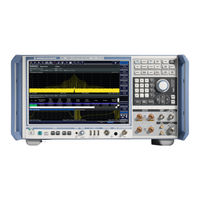
Rohde & Schwarz FSW13 User Manual (166 pages)
Spectrum Analyzers/Phase Noise Measurements
Brand:
Rohde & Schwarz
| Category:
Measuring Instruments
| Size: 4.56 MB
Table of Contents
Table of Contents
3
1 Preface
5
About this Manual
5
Documentation Overview
6
Conventions Used in the Documentation
7
2 Welcome to the Phase Noise Measurement Application
9
Starting the Application
9
Understanding the Display Information
10
3 Measurements and Result Displays
14
Phase Noise Diagram
14
Residual Noise
15
Spot Noise
16
Spur List
17
Sweep Result List
18
Spectrum Monitor
19
Frequency Drift
20
Frequency and Level Stability
21
Reference Measurement
21
4 Measurement Basics
22
Phase Noise Diagram
22
Spurs and Spur Removal
22
Residual Effects
23
Measurement Range
24
Sweep Modes
25
Trace Averaging
25
Frequency Determination
27
Level Determination
30
Signal Attenuation
30
Using Limit Lines
31
Analyzing Several Traces - Trace Mode
33
Using Markers
35
5 Configuration
36
Configuration Overview
36
Default Settings for Phase Noise Measurements
37
Configuring the Frontend
38
Controlling the Measurement
40
Configuring the Measurement Range
43
Performing Measurements
46
Configuring In- and Outputs
48
Automatic Measurement Configuration
49
6 Analysis
51
Configuring Graphical Result Displays
51
6.1.2 Configuring Traces
53
Smoothing Type
53
Trace Offset
53
Trace Smoothing
53
Trace Config
54
Traces
54
Trace Export
55
Copy Trace
55
Configure Numerical Result Displays
56
Trace Math
56
Frequency Drift: Trace 1 (on Off)
56
Spectrum Monitor: Raw Trace / Trk Trace (on Off)
56
Spur Removal / Spur Threshold
56
Using Limit Lines
58
Using Markers
65
7 How to Configure Phase Noise Measurements
68
Customizing the Measurement Range
68
8 Remote Control Commands for Phase Noise Measurements
70
Performing a Basic Phase Noise Measurement
68
Common Suffixes
70
Introduction
71
Controlling the Phase Noise Measurement Channel
76
Performing Measurements
80
Configuring the Result Display
85
Configuring the Frontend
92
Controlling the Measurement
95
Configuring the Measurement Range
99
Using Limit Lines
106
Graphical Display of Phase Noise Results
116
8.11 Configure Numerical Result Displays
126
Configure Numerical Result Displays
126
The Following Commands Are Necessary to Configure the Numerical Phase Noise Result Displays. Configuring Residual Noise Measurements
126
Calculate<N>:Evaluation:start
126
Calculate<N>:Evaluation[:State]
127
Calculate<N>:Evaluation:stop
127
Calculate<N>:Evaluation:user<Range>:Start
127
Calculate<N>:Evaluation:user<Range>:Stop
128
Calculate<N>:Evaluation:user<Range>:Trace
128
Reading out Residual Noise Results
129
Configuring Spot Noise Measurements
131
Reading out the Spur List
134
Reading out Measured Values
135
Reading out the Sweep Result List
136
8.12 Using Markers
139
Using Markers
139
Calculate<N>:Marker<M>:Aoff
139
Calculate<N>:Marker<M>[:State]
139
Calculate<N>:Marker<M>:Trace
140
Calculate<N>:Marker<M>:X
140
Using Delta Markers
141
Calculate<N>:Marker<M>:Y
141
Configuring Markers
144
Configuring In- and Outputs
145
Using the Marker Zoom
145
Automatic Measurement Configuration
146
Using the Status Register
147
Remote Control Example Scripts
153
List of Remote Commands (Phase Noise)
159
Index
164
Advertisement
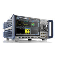
Rohde & Schwarz FSW13 Getting Started (123 pages)
Signal and Spectrum Analyzer
Brand:
Rohde & Schwarz
| Category:
Measuring Instruments
| Size: 15.62 MB
Table of Contents
Table of Contents
3
1 Safety and Regulatory Information
7
Safety Instructions
7
Warning Messages in the Documentation
10
Korea Certification Class B
11
2 Documentation Overview
12
Getting Started Manual
12
User Manuals and Help
12
Data Sheets and Brochures
13
Instrument Security Procedures
13
Printed Safety Instructions
13
Service Manual
13
Application Notes, Application Cards, White Papers, Etc
14
3 Key Features
15
Release Notes and Open-Source Acknowledgment (OSA)
14
Lifting and Carrying
16
4 Preparing for Use
16
Unpacking and Checking
16
Choosing the Operating Site
17
Setting up the Product
17
Connecting the AC Power
19
Switching the Instrument on and off
20
Connecting to LAN
21
Connecting a Keyboard
22
Connecting an External Monitor
23
Windows Operating System
25
Logging on
27
Checking the Supplied Options
30
Performing a Self-Alignment
30
Considerations for Test Setup
31
Protecting Data Using the Secure User Mode
32
5 Instrument Tour
35
Front Panel View
35
Rear Panel View
48
6 Trying out the Instrument
60
Measuring a Basic Signal
60
Displaying a Spectrogram
62
Activating Additional Measurement Channels
64
Performing Sequential Measurements
69
Setting and Moving a Marker
70
Displaying a Marker Peak List
72
Zooming into the Display
73
Zooming into the Display Permanently
77
Saving Settings
79
Printing and Saving Results
81
7 Operating the Instrument
83
Understanding the Display Information
83
Accessing the Functionality
94
Changing the Focus
100
Entering Data
101
Touchscreen Gestures
104
Displaying Results
108
Background Information: the Smartgrid Principle
111
How to Activate Smartgrid Mode
113
How to Add a New Result Window
113
How to Close a Result Window
114
How to Arrange the Result Windows
114
Getting Help
116
8 Contacting Customer Support
118
Index
119
Rohde & Schwarz FSW13 Getting Started (113 pages)
Signal and Spectrum Analyzer
Brand:
Rohde & Schwarz
| Category:
Measuring Instruments
| Size: 5.74 MB
Table of Contents
Table of Contents
3
1 Preface
5
Key Features
5
Documentation Overview
6
Conventions Used in the Documentation
8
2 Preparing for Use
9
Putting into Operation
9
Windows Operating System
18
Connecting USB Devices
21
Connecting an External Monitor
23
Setting up a Network (LAN) Connection
25
Configuring the Initial Instrument Settings
30
Protecting Data Using the Secure User Mode
31
3 Instrument Tour
34
Front Panel View
34
Rear Panel View
50
4 Trying out the Instrument
58
Measuring a Basic Signal
58
Displaying a Spectrogram
61
Activating Additional Measurement Channels
62
Performing Sequential Measurements
67
Setting and Moving a Marker
68
Displaying a Marker Peak List
70
Zooming into the Display
71
Saving Settings
75
Printing and Saving Results
77
5 Operating the Instrument
78
Understanding the Display Information
78
Accessing the Functionality
89
Changing the Focus
89
Entering Data
90
Displaying Results
92
Getting Help
101
Remote Control
104
6 Obtaining Technical Support
106
Index
108
Advertisement
Related Products
Rohde & Schwarz FSW-K40
Rohde & Schwarz FSW8
Rohde & Schwarz FSW67
Rohde & Schwarz FSW85
Rohde & Schwarz FSW43
Rohde & Schwarz FSW Series
Rohde & Schwarz FSW-K7
Rohde & Schwarz FSWP
Rohde & Schwarz R&S FSW-K10
Rohde & Schwarz R&S FSW-K106
Rohde & Schwarz Categories
Measuring Instruments
Test Equipment
Portable Generator
Power Supply
Accessories
More Rohde & Schwarz Manuals
Login
Sign In
OR
Sign in with Facebook
Sign in with Google
Upload manual
Upload from disk
Upload from URL