Sign In
Upload
Manuals
Brands
Rockwell Automation Manuals
Controller
2080-L70E-24QBB
Rockwell Automation 2080-L70E-24QBB Manuals
Manuals and User Guides for Rockwell Automation 2080-L70E-24QBB. We have
1
Rockwell Automation 2080-L70E-24QBB manual available for free PDF download: User Manual
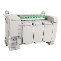
Rockwell Automation 2080-L70E-24QBB User Manual (390 pages)
Brand:
Rockwell Automation
| Category:
Controller
| Size: 40 MB
Table of Contents
Table of Contents
3
Preface
11
About this Publication
11
Conformal Coated Catalogs
11
Download Firmware, AOP, EDS, and Other Files
11
Summary of Changes
11
Additional Resources
11
Hardware Overview
15
Hardware Features
16
Micro830 Controllers
16
Micro850 Controllers
17
Micro870 Controllers
19
Programming Cables
21
Embedded Serial Port Cables
21
Embedded Ethernet Support
22
About Your Controller
23
Programming Software for Micro800 Controllers
23
Obtain Connected Components Workbench Software
23
Use Connected Components Workbench Software
23
Controller Changes in Run Mode
23
Using Run Mode Change (RMC)
23
Uncommitted Changes
25
RMC Memory
25
Limitations of RMC
27
Using Run Mode Configuration Change (RMCC)
27
Using Modbus RTU Communication
28
Using Ethernet/Ip Communication
30
Safety Considerations
31
Disconnect Main Power
31
Safety Circuits
32
Power Distribution
32
Periodic Tests of Master Control Relay Circuit
32
Power Considerations
32
Isolation Transformers
32
Power Supply Inrush
32
Loss of Power Source
33
Input States on Power down
33
Other Types of Line Conditions
33
Preventing Excessive Heat
33
Master Control Relay
33
Using Emergency-Stop Switches
34
Install Your Controller
37
Controller Mounting Dimensions
37
Mounting Dimensions
37
DIN Rail Mounting
39
Panel Mounting
39
Panel Mounting Dimensions
39
System Assembly
41
Wire Your Controller
43
Wiring Requirements and Recommendation
43
Use Surge Suppressors
44
Recommended Surge Suppressors
45
Grounding the Controller
46
Wiring Diagrams
46
Controller I/O Wiring
50
Minimize Electrical Noise
50
Analog Channel Wiring Guidelines
50
Minimize Electrical Noise on Analog Channels
50
Grounding Your Analog Cable
51
Wiring Examples
51
Embedded Serial Port Wiring
52
Communication Connections
55
Overview
55
Supported Communication Protocols
55
Modbus RTU
56
CIP Serial Client/Server - DF1
57
Ascii
57
Modbus TCP Client/Server
57
CIP Symbolic Client/Server
57
CIP Client Messaging
58
Sockets Client/Server TCP/UDP
59
CIP Communications
59
Pass-Thru
59
Examples of Supported Architectures
59
Use Modems with Micro800 Controllers
60
Making a DF1 Point-To-Point Connection
60
Construct Your Own Modem Cable
60
Configure Serial Port
60
Configure CIP Serial Driver
61
Configure Modbus RTU
64
Configure ASCII
65
Configure Ethernet Settings
66
Validate IP Address
67
Ethernet Host Name
68
Configure CIP Serial Driver
68
OPC Support Using Factorytalk Linx
68
Overview
69
Channel Configuration for DNP3 Slave
69
Serial Port Link Layer Configuration
70
Ethernet Layer Configuration
71
DNP3 Slave Application Layer Configuration
72
Serial Link Layer Configuration Parameters
72
Ethernet Layer Configuration Parameters
75
DNP3 Slave Application Layer Configuration Parameters
79
DNP3 Slave Application Layer
92
Function Codes
92
Internal Indications
96
DNP3 Objects and Controller Variables
96
DNP3 Object Data
97
DNP3 Configuration
98
DNP3 Data Set Object
98
Object Quality Flags
104
DNP3 Device Attribute Object
106
Event Reporting
108
Generate Events
108
DNP3 10K Event Logging
110
Control Generating Event
110
Report Event by Polled Response
111
Report Event by Unsolicited Response
111
Collision Avoidance
112
Time Synchronization
113
Diagnostics
114
Diagnostics for Ethernet Channel
115
Diagnostics for Secure Authentication
116
Function Codes
116
Implementation Table
117
Program Execution in Micro800
123
Overview of Program Execution
123
Execution Rules
124
Optional Module
124
Controller Load and Performance Considerations
124
Periodic Execution of Programs
125
Power up and First Scan
125
Variable Retention
125
Memory Allocation
126
Guidelines and Limitations for Advanced Users
126
Ethernet/Ip Network
129
Overview
129
Ethernet/Ip Network Functionality
129
Star Network Topology
130
Implicit Messaging I/O Nodes on an Ethernet/Ip Network
130
Devices Included in the Node Count
131
Devices Excluded from the Node Count
131
How to Add Powerflex 520-Series and Kinetix 5100 Drives over Ethernet/Ip
131
Add a Powerflex 523 or Powerflex 525 Drive
132
Add a Kinetix 5100 Drive
133
Modify an Existing Module
134
Module Properties
135
Requested Packet Interval
136
Type Definition in Module Dialog
136
Module Inhibiting
137
Predefined Tags in Powerflex 520-Series and Kinetix 5100 Drives
138
Use of the User-Defined Function Block Library
143
Download the User-Defined Function Block Instruction Files
144
Import the User-Defined Function Block Instruction Files
144
Connection Fault Codes
147
Motion Control
157
PTO Motion Control
157
Use the Micro800 Motion Control Feature
158
Input and Output Signals
159
Motion Control Function Blocks
162
General Rules for the Motion Control Function Blocks
163
Motion Axis and Parameters
170
Axis States
171
Limits
172
Motion Stop
174
Motion Direction
175
Axis Elements and Data Types
175
Axis Error Scenarios
176
Mc_Engine_Diag Data Type
177
Function Block and Axis Status Error Codes
177
Major Fault Handling
179
Motion Axis Configuration in Connected Components Workbench
180
Add New Axis
180
Edit Axis Configuration
181
Axis Start/Stop Velocity
187
Real Data Resolution
187
PTO Pulse Accuracy
189
Motion Axis Parameter Validation
189
Delete an Axis
189
Monitor an Axis
190
Homing Function Block
190
Conditions for Successful Homing
191
Mc_Home_Abs_Switch
191
Mc_Home_Limit_Switch
192
Mc_Home_Ref_With_Abs
193
Mc_Home_Ref_Pulse
194
Mc_Home_Direct
195
Use PTO for PWM Control
195
POU Pwm_Program
197
HSC Feedback Axis
197
Use the High-Speed Counter and Programmable Limit Switch
199
High-Speed Counter Overview
199
Programmable Limit Switch Overview
199
What Is High-Speed Counter
199
Features and Operation
200
HSC Inputs and Wiring Mapping
201
High-Speed Counter (HSC) Data Structures
202
HSC APP Data Structure
202
HSC STS (HSC Status) Data Structure
211
High-Speed Counter (HSC) Function Block
216
HSC Commands (Hsccmd)
216
HSC_SET_STS Function Block
217
Programmable Limit Switch (PLS) Function
218
PLS Data Structure
218
PLS Operation
218
PLS Example
219
HSC Interrupts
220
HSC Interrupt Configuration
220
HSC Interrupt POU
221
HSC Interrupt Status Information
222
Controller Security
225
Protected Mode
225
Exclusive Access
225
Password Protection
225
Compatibility
226
Work with a Locked Controller
227
Upload from a Password-Protected Controller
227
Debug a Password-Protected Controller
227
Download to a Password-Protected Controller
227
Transfer Controller Program and Password-Protect Receiving Controller
228
Back up and Restore a Password-Protected Controller
228
Configure Controller Password
229
Recover from a Lost Password
229
Using the Memory Module Plug-In
229
Using Microsd Cards
233
Overview
233
Project Backup and Restore
234
Backup and Restore Directory Structure
235
Power-Up Settings in Configmefirst.txt
236
General Configuration Rules in Configmefirst.txt
237
Configmefirst.txt Errors
237
Deliver Project Updates to Customers through Email
238
Data Log
240
Data Log Directory Structure
241
Data Log Function (DLG) Block
242
Recipe
245
Recipe Directory Structure
246
Quickstart Projects for Data Log and Recipe Function Blocks
248
Use the Data Log Feature
248
Use the Recipe Feature
254
Modbus Mapping for Micro800
261
Modbus Mapping
261
Endian Configuration
261
Mapping Address Space and Supported Data Types
261
Example 1, Panelview 800 HMI (Master) to Micro800 (Slave)
262
Example 2, Micro800 (Master) to Powerflex 4M Drive (Slave)
263
Performance
265
Flash Upgrade Your Micro800 Firmware
267
Flash Upgrade from Microsd Card
269
Establish Communications between Rslinx and a Micro830/Micro850/Micro870
272
Controller through USB
272
Configure Controller Password
276
Set Controller Password
276
Change Password
277
Clear Password
278
Use the High-Speed Counter
279
Create the HSC Project and Variables
280
Assign Values to the HSC Variables
283
Assign Variables to the Function Block
285
Run the High-Speed Counter
286
Use the Programmable Limit Switch (PLS) Function
287
Forcing I/Os
288
Checking if Forces (Locks) Are Enabled
289
I/O Forces after a Power Cycle
290
Use Run Mode Change
290
Create the Project
290
Edit the Project Using Run Mode Change
292
User Interrupts
295
Information about Using Interrupts
295
What Is an Interrupt
295
When Can the Controller Operation be Interrupted
296
Priority of User Interrupts
296
User Interrupt Configuration
297
User Fault Routine
297
User Interrupt Instructions
298
STIS - Selectable Timed Start
298
UID - User Interrupt Disable
299
UIE - User Interrupt Enable
300
UIF - User Interrupt Flush
301
UIC - User Interrupt Clear
302
Using the Selectable Timed Interrupt (STI) Function
302
Selectable Time Interrupt (STI) Function Configuration and Status
303
STI Function Configuration
303
STI Function Status Information
304
Using the Event Input Interrupt (EII) Function
305
Event Input Interrupt (EII) Function Configuration and Status
305
EII Function Configuration
305
EII Function Status Information
306
Troubleshooting
307
Status Indicators on the Controller
307
Normal Operation
308
Error Codes
309
Fault Types
309
Corrective Action for Recoverable and Non-Recoverable Faults
313
Retrieve a Fault Log
314
Controller Error Recovery Model
315
Ethernet Diagnostics
316
General Diagnostic Information
317
Ethernet/Ip Overview Diagnostic Information
319
System Diagnostic Information
321
Controller Diagnostic Information
322
Calling Rockwell Automation for Assistance
322
PID Function Blocks
323
PID Function Block
324
IPIDCONTROLLER Function Block
326
How to Autotune
328
How Autotune Works
329
Troubleshooting an Autotune Process
329
PID Application Example
330
PID Code Sample
331
System Loading
333
Connect to Networks Using DF1
335
DF1 Full-Duplex Protocol
335
DF1 Half-Duplex Protocol
336
DF1 Half-Duplex Operation
336
Considerations When Communicating as a DF1 Slave on a Multi-Drop Link
337
Using Modems with Micro800 Programmable Controllers
337
Modem Control Line Operation
338
DF1 Full-Duplex
338
DF1 Half-Duplex Slave
338
DF1 Half Duplex Master
338
DF1 Radio Modem
339
Configure DF1 Half-Duplex Parameters
339
RTS Send Delay and RTS off Delay
339
Configure a Standard-Mode DF1 Half-Duplex Master Station
340
Minimum DF1 Half-Duplex Master ACK Timeout
342
Determining Minimum Master ACK Timeout
342
DF1 Half-Duplex Master Communication Diagnostics
343
Configure a Message-Based Mode DF1 Half-Duplex
343
Master Station
343
Configure a Slave Station
346
Configure Poll Timeout
347
DF1 Half-Duplex Slave Communication Diagnostics
347
Configure a Radio Modem Station
348
DF1 Radio Modem Communication Diagnostics
349
Configure the Store and Forward Table
350
User-Defined Function Block Motion Instructions
353
Kinetix 5100 Drive Device Object UDFB
355
Configure Udfbs for Kinetix 5100 Drives
357
Rac_Dvc_K5100
357
Rac_Udt_Itf_K5100_Cfg
357
Rac_Udt_Itf_K5100_Set
359
Rac_Udt_Itf_K5100_Cmd
360
Rac_Udt_Itf_K5100_Sts
360
UDFB Motion Instruction Details
362
Rac_Opr_K5100_Mso
362
Rac_Opr_K5100_Msf
363
Rac_Opr_K5100_Mafr
364
Rac_Opr_K5100_Mas
365
Rac_Opr_K5100_Maj
367
Rac_Opr_K5100_Mam
368
Rac_Opr_K5100_Mai
372
Rac_Opr_K5100_Mag
374
Rac_Opr_K5100_Mah
377
Rac_Opr_K5100_Mat
380
Error Codes
382
Advertisement
Advertisement
Related Products
Rockwell Automation 2080-L70E-24AWB
Rockwell Automation 2080-L70E-24QWB
Rockwell Automation 2080-L70E-24QWBK
Rockwell Automation 2080-L70E-24QWBN
Rockwell Automation 2080-L70E-24QBBK
Rockwell Automation 2080-L70E-24QBBN
Rockwell Automation 2080-L50E-24QVB
Rockwell Automation 2080-LC50-48AWB
Rockwell Automation 2080-LC70-24AWB
Rockwell Automation 2080-LC70-24QBBK
Rockwell Automation Categories
Controller
Control Unit
Power Supply
DC Drives
Industrial Equipment
More Rockwell Automation Manuals
Login
Sign In
OR
Sign in with Facebook
Sign in with Google
Upload manual
Upload from disk
Upload from URL