Rockwell Automation Allen-Bradley Micro830 User Manual
Hide thumbs
Also See for Allen-Bradley Micro830:
- Installation instructions manual (17 pages) ,
- Original instructions manual (290 pages) ,
- User manual (350 pages)
Table of Contents
Advertisement
Micro830, Micro850, and Micro870
Programmable Controllers
Micro830 Controller Catalog Numbers 2080-LC30-10QWB, 2080-LC30-10QVB, 2080-LC30-16AWB, 2080-LC30-16QWB,
2080-LC30-16QVB, 2080-LC30-24QWB, 2080-LC30-24QVB, 2080-LC30-24QBB, 2080-LC30-48AWB, 2080-LC30-48QWB,
2080-LC30-48QVB, 2080-LC30-48QBB
Micro850 Controller Catalog Numbers 2080-LC50-24AWB, 2080-L50E-24AWB, 2080-LC50-24QWB, 2080-L50E-24QWB,
2080-LC50-24QVB, 2080-L50E-24QVB, 2080-LC50-24QBB, 2080-L50E-24QBB, 2080-LC50-48AWB, 2080-L50E-48AWB,
2080-LC50-48QWB, 2080-L50E-48QWB, 2080-LC50-48QWBK, 2080-L50E-48QWBK, 2080-LC50-48QVB,
2080-L50E-48QVB, 2080-LC50-48QBB, 2080-L50E-48QBB
Micro870 Controller Catalog Numbers 2080-LC70-24AWB, 2080-L70E-24AWB, 2080-LC70-24QWB, 2080-L70E-24QWB,
2080-LC70-24QWBK, 2080-L70E-24QWBK, 2080-L70E-24QWBN, 2080-LC70-24QBB, 2080-L70E-24QBB,
2080-LC70-24QBBK, 2080-L70E-24QBBK, 2080-L70E-24QBBN
User Manual
Original Instructions
Advertisement
Table of Contents
Troubleshooting

Related Manuals for Rockwell Automation Allen-Bradley Micro830


Summary of Contents for Rockwell Automation Allen-Bradley Micro830
- Page 1 Micro830, Micro850, and Micro870 Programmable Controllers Micro830 Controller Catalog Numbers 2080-LC30-10QWB, 2080-LC30-10QVB, 2080-LC30-16AWB, 2080-LC30-16QWB, 2080-LC30-16QVB, 2080-LC30-24QWB, 2080-LC30-24QVB, 2080-LC30-24QBB, 2080-LC30-48AWB, 2080-LC30-48QWB, 2080-LC30-48QVB, 2080-LC30-48QBB Micro850 Controller Catalog Numbers 2080-LC50-24AWB, 2080-L50E-24AWB, 2080-LC50-24QWB, 2080-L50E-24QWB, 2080-LC50-24QVB, 2080-L50E-24QVB, 2080-LC50-24QBB, 2080-L50E-24QBB, 2080-LC50-48AWB, 2080-L50E-48AWB, 2080-LC50-48QWB, 2080-L50E-48QWB, 2080-LC50-48QWBK, 2080-L50E-48QWBK, 2080-LC50-48QVB, 2080-L50E-48QVB, 2080-LC50-48QBB, 2080-L50E-48QBB Micro870 Controller Catalog Numbers 2080-LC70-24AWB, 2080-L70E-24AWB, 2080-LC70-24QWB, 2080-L70E-24QWB, 2080-LC70-24QWBK, 2080-L70E-24QWBK, 2080-L70E-24QWBN, 2080-LC70-24QBB, 2080-L70E-24QBB,...
- Page 2 If this equipment is used in a manner not specified by the manufacturer, the protection provided by the equipment may be impaired. In no event will Rockwell Automation, Inc. be responsible or liable for indirect or consequential damages resulting from the use or application of this equipment.
-
Page 3: Table Of Contents
Using Emergency-Stop Switches ........34 Rockwell Automation Publication 2080-UM002N-EN-E - November 2022... - Page 4 OPC Support Using FactoryTalk Linx ......... 68 Rockwell Automation Publication 2080-UM002N-EN-E - November 2022...
- Page 5 Star Network Topology ..........130 Implicit Messaging I/O Nodes on an EtherNet/IP Network ..... . 130 Rockwell Automation Publication 2080-UM002N-EN-E - November 2022...
- Page 6 Use PTO for PWM Control ..........195 Rockwell Automation Publication 2080-UM002N-EN-E - November 2022...
- Page 7 Data Log............. . . 240 Rockwell Automation Publication 2080-UM002N-EN-E - November 2022...
- Page 8 UID - User Interrupt Disable..........299 Rockwell Automation Publication 2080-UM002N-EN-E - November 2022...
- Page 9 Calling Rockwell Automation for Assistance ........322...
- Page 10 ............... 383 Rockwell Automation Publication 2080-UM002N-EN-E - November 2022...
-
Page 11: Preface
See the Online Help provided with Connected Components Workbench™ software for more information on programming your Micro800 controller. Rockwell Automation recognizes that some of the terms that are currently used in our industry and in this publication are not in alignment with the movement toward inclusive language in technology. - Page 12 Provides guidance on how to conduct security assessments, implement Rockwell System Security Design Guidelines Reference Manual, Automation products in a secure system, harden the control system, manage user access, publication SECURE-RM001 and dispose of equipment. Rockwell Automation Publication 2080-UM002N-EN-E - November 2022...
- Page 13 Industrial Automation Wiring and Grounding Guidelines, publication 1770-4.1 Provides general guidelines for installing a Rockwell Automation® industrial system. Product Certifications website, rok.auto/certifications. Provides declarations of conformity, certificates, and other certification details. You can download the latest version of Connected Components Workbench software for your Micro800 controller at rok.auto/ccw.
- Page 14 Notes: Rockwell Automation Publication 2080-UM002N-EN-E - November 2022...
-
Page 15: Hardware Overview
This chapter provides an overview of the Micro830®, Micro850®, and Micro870® controller hardware features. It has the following topics: Topic Page Hardware Features Micro830 Controllers Micro850 Controllers Micro870 Controllers Programming Cables Embedded Serial Port Cables Embedded Ethernet Support Rockwell Automation Publication 2080-UM002N-EN-E - November 2022... -
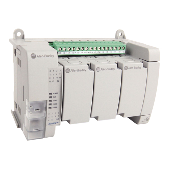
Page 16: Hardware Features
Troubleshooting on page 307 for descriptions of status indicator operation for troubleshooting purposes. Micro830 Controllers Micro830 10/16-point controllers and status indicators Controller Status indicator Micro830 24-point controllers and status indicators Controller Status indicator Rockwell Automation Publication 2080-UM002N-EN-E - November 2022... -
Page 17: Micro850 Controllers
Serial communications status Run status Output status Fault status (1) For detailed description of the different status LED indicators, see Troubleshooting on page 307. Micro850 Controllers Micro850 24-point controllers and status indicators Controller Status indicators Rockwell Automation Publication 2080-UM002N-EN-E - November 2022... - Page 18 40-pin high-speed plug-in connector RS-232/RS-485 non-isolated combo serial port RJ-45 EtherNet/IP connector Removable I/O terminal block (with embedded yellow and green LED indicators) Right-side cover Optional AC power supply Mounting screw hole / mounting foot Rockwell Automation Publication 2080-UM002N-EN-E - November 2022...
-
Page 19: Micro870 Controllers
Input status Fault status Module Status Force status Network Status Serial communications status Power status Output status Run status (1) For detailed descriptions of the different status LED indicators, see Troubleshooting on page 307. Rockwell Automation Publication 2080-UM002N-EN-E - November 2022... - Page 20 – – 2080-L50E-48QWB – – – – 2080-LC50-48QWBK – – – – 2080-L50E-48QWBK – – – – 2080-LC50-48QVB – – – 2080-L50E-48QVB – – – 2080-LC50-48QBB – – – 2080-L50E-48QBB – – – Rockwell Automation Publication 2080-UM002N-EN-E - November 2022...
-
Page 21: Programming Cables
9-pin D Shell 8-pin Mini DIN to 6-pin RS-485 terminal — 30 cm (11.8in.) 1763-NC01 series A block (1) Series C or later for Class 1 Div 2 applications. Rockwell Automation Publication 2080-UM002N-EN-E - November 2022... -
Page 22: Embedded Ethernet Support
Ethernet Status Indication Micro850 and Micro870 controllers also support two LEDs for EtherNet/IP™ to indicate the following: • Module status • Network status Troubleshooting on page 307 for descriptions of Module and Network status indicators. Rockwell Automation Publication 2080-UM002N-EN-E - November 2022... -
Page 23: About Your Controller
About Your Controller Programming Software for Connected Components Workbench software is a set of collaborative tools supporting Micro800 controllers. It is based on Rockwell Automation and Microsoft® Visual Studio® Micro800 Controllers technology and offers controller programming, device configuration and integration with HMI editor. - Page 24 After you choose to accept or undo the changes, the value of the variable is reset to zero. IMPORTANT When a Test Logic is performed, or undoing changes after the Test Logic is completed, any active communication instructions will be aborted while the changes are downloaded to the controller. Rockwell Automation Publication 2080-UM002N-EN-E - November 2022...
-
Page 25: Uncommitted Changes
(Default size = 2KB) 1st change and 2nd change and 3rd change and Test Logic Test Logic Test Logic (Add logic) (Remove logic) (Add logic) Free memory Free RMC memory Used RMC memory Used memory Rockwell Automation Publication 2080-UM002N-EN-E - November 2022... - Page 26 Do not use RMC if you are near the limits of your controller memory. Insufficient Controller Memory Example Controller Memory RMC Memory (for User Program + Data) (Default size = 2KB) Free RMC memory Error will occur due to insufficient controller memory remaining Used memory Rockwell Automation Publication 2080-UM002N-EN-E - November 2022...
-
Page 27: Limitations Of Rmc
IMPORTANT During RMCC the scan time may increase to close to 100 ms. Do not perform RMCC if the controller is performing time critical operations. (1) Approximately 85 boolean instructions for Micro850 (2080-L50E) and Micro870 (2080-L70E) controllers. Rockwell Automation Publication 2080-UM002N-EN-E - November 2022... -
Page 28: Using Modbus Rtu Communication
CIP Generic Message Parameters for RMCC using Modbus RTU Parameter Value Service Class 2 – Embedded serial port Instance 5, 6, 7, 8, or 9 – Plug-in modules Attribute ReqData New node address, 1 ReqLen Rockwell Automation Publication 2080-UM002N-EN-E - November 2022... - Page 29 You can verify that the node address has changed after performing RMCC by looking at the Communication Diagnostics tab for the controller. RMCC Modbus Example – Verify Address Change Rockwell Automation Publication 2080-UM002N-EN-E - November 2022...
-
Page 30: Using Ethernet/Ip Communication
RMCC EtherNet/IP Example – Set the New IP Address For this example, the new IP Address is set to the following: • IP address = 192.168.1.10 • Subnet mask = 255.255.255.0 • Gateway address = 192.168.1.1 Rockwell Automation Publication 2080-UM002N-EN-E - November 2022... -
Page 31: Safety Considerations
(pneumatic and hydraulic) should be de-energized before working on a machine or process controlled by a controller. WARNING: Explosion Hazard Do not replace components, connect equipment, or disconnect equipment unless power has been switched off. Rockwell Automation Publication 2080-UM002N-EN-E - November 2022... -
Page 32: Safety Circuits
However, the effect of a voltage sag on other equipment should be considered. For example, a deep voltage sag may reset a computer connected to the same power source. Rockwell Automation Publication 2080-UM002N-EN-E - November 2022... -
Page 33: Loss Of Power Source
Overtravel limit switches or mushroom-head push buttons are wired in series so that when any of them opens, the master control relay is de-energized. This removes power to input and output device circuits. See Figure 1 on page 35 Figure 2 on page Rockwell Automation Publication 2080-UM002N-EN-E - November 2022... -
Page 34: Using Emergency-Stop Switches
The following illustrations show the Master Control Relay wired in a grounded system. In most applications input circuits do not require MCR protection; however, if you need to remove power from all field devices, you must include MCR contacts in series with input power wiring. Rockwell Automation Publication 2080-UM002N-EN-E - November 2022... - Page 35 I/O circuits DC power supply. Use IEC 950/EN 60950 (Hi) (Lo) 24V DC I/O circuits Line terminals: Connect to terminals of power supply. Line terminals: Connect to 24V DC terminals of power supply. Rockwell Automation Publication 2080-UM002N-EN-E - November 2022...
- Page 36 DC power supply. Use NEC Class 2 for UL Listing. (Lo) (Hi) 24 V DC I/O circuits Line terminals: Connect to terminals of power supply Line terminals: Connect to 24V DC terminals of power supply. Rockwell Automation Publication 2080-UM002N-EN-E - November 2022...
-
Page 37: Install Your Controller
Micro830 10-point and 16-point Controllers 2080-LC30-10QWB, 2080-LC30-10QVB, 2080-LC30-16AWB, 2080-LC30-16QWB, 2080-LC30-16QVB 100 (3.94) 80 (3.15) 90 (3.54) Measurements in mm (in.) Micro830 24-point Controllers 2080-LC30-24QW8B, 2080-LC30-24QVB, 2080-LC30-24QBB 80 (3.15) 150 (5.91) 90 (3.54) Measurements in mm (in.) Rockwell Automation Publication 2080-UM002N-EN-E - November 2022... - Page 38 2080-PS120-240VAC or expansion I/O modules, make sure that there is 50.8 mm (2 in.) of space on all sides after attaching the optional parts. Rockwell Automation Publication 2080-UM002N-EN-E - November 2022...
-
Page 39: Din Rail Mounting
IMPORTANT For instructions on how to install your Micro800 system with expansion I/O, see Micro800 Expansion I/O Modules User Manual, publication 2080-UM003. Panel Mounting Dimensions Micro830 10-Point and 16-Point Controllers 2080-LC30-10QWB, 2080-LC30-10QVB, 2080-LC30-16AWB, 2080-LC30-16QWB, 2080-LC30-16QVB 86 mm (3.39 in.) Rockwell Automation Publication 2080-UM002N-EN-E - November 2022... - Page 40 2080-L70E-24QBBK, 2080-L70E-24QBBN 131 mm (5.16 in.) Micro830 48-Point Controllers 2080-LC30-48AWB, 2080-LC30-48QWB, 2080-LC30-48QVB, 2080-LC30-48QBB Micro850 48-point Controllers 2080-LC50-48AWB, 2080-LC50-48QWB, 2080-LC50-48QWBK, 2080-LC50-48QBB, 2080-LC50-48QVB, 2080-L50E-48AWB, 2080-L50E-48QWB, 2080-L50E-48QWBK, 2080-L50E-48QBB, 2080-L50E-48QVB 108 mm (4.25 in.) 108 mm (4.25 in.) Rockwell Automation Publication 2080-UM002N-EN-E - November 2022...
-
Page 41: System Assembly
Micro830, Micro850, and Micro870 24-point Controllers (Side) 87 (3.42) 80 (3.15) Micro830/Micro850/Micro870 24-pt controller with Micro800 power supply Expansion I/O Slots (Applicable to Micro850 and Micro870 only) Single-width (1st slot) Double-width (2nd slot) Measurements in mm (in.) 2085-ECR (terminator) Rockwell Automation Publication 2080-UM002N-EN-E - November 2022... - Page 42 Micro830 and Micro850 48-point Controllers (Side) (3.42) 80 (3.15) Micro830/Micro850 48-pt controller with Micro800 power supply Expansion I/O Slots (Applicable to Micro850 only) Single-width (1st slot) Measurements in mm (in.) Double-width (2nd slot) 2085-ECR (terminator) Rockwell Automation Publication 2080-UM002N-EN-E - November 2022...
-
Page 43: Wire Your Controller
Label wiring to all devices in the system. Use tape, shrink-tubing, or other dependable means for labeling purposes. In addition to labeling, use colored insulation to identify wiring based on signal characteristics. For example, you may use blue for DC wiring and red for AC wiring. Rockwell Automation Publication 2080-UM002N-EN-E - November 2022... -
Page 44: Use Surge Suppressors
Allen-Bradley surge suppressor, shown in Figure 5. These components must be appropriately rated to suppress the switching transient characteristic of the particular inductive device. See Recommended Surge Suppressors on page 45 for recommended suppressors. Rockwell Automation Publication 2080-UM002N-EN-E - November 2022... -
Page 45: Recommended Surge Suppressors
(2) Catalog numbers for screwless terminals include the string ’CR’ after ’100-’. For example: Cat. No. 100-FSC48 becomes Cat. No. 100-CRFSC48; Cat. No. 100-FSV55 becomes 100-CRFSV55; and so on. (3) For use on the interposing relay. (4) For use on the contactor or starter. Rockwell Automation Publication 2080-UM002N-EN-E - November 2022... -
Page 46: Grounding The Controller
2080-LC30-16AWB, 2080-LC30-16QWB Input terminal block COM0 I-01 I-03 I-04 I-06 I-08 I-00 I-02 COM1 I-05 I-07 I-09 Output terminal block +DC24 O-04 -DC24 O-00 O-01 O-02 O-03 O-05 2080-LC30-16AWB has no high-speed inputs. Rockwell Automation Publication 2080-UM002N-EN-E - November 2022... - Page 47 1606-XLP60EQ power supply instead of a 2080-PS120-240VAC power supply. Make sure to wire both the Micro870 controller and 2085-EP24VDC expansion power supply to the same 1606-XLP60EQ power supply. Rockwell Automation Publication 2080-UM002N-EN-E - November 2022...
- Page 48 I-06 COM1 I-09 I-11 I-13 +DC24 +CM0 O-01 +CM1 O-03 O-05 O-07 O-09 +24 VDC -DC24 O-00 -CM0 O-02 O-04 O-06 O-08 -CM1 -24 VDC +DC d +DC e -DC d -DC e Rockwell Automation Publication 2080-UM002N-EN-E - November 2022...
- Page 49 +DC24 -DC24 O-00 O-01 O-02 O-03 O-04 O-05 O-06 TERMINAL BLOCK 2 O-08 O-10 O-13 O-15 O-16 O-18 O-07 O-09 O-11 O-12 O-14 O-17 O-19 TERMINAL BLOCK 4 2080-LC30-48AWB has no high-speed inputs. Rockwell Automation Publication 2080-UM002N-EN-E - November 2022...
-
Page 50: Controller I/O Wiring
However, because of the variety of applications and environments where analog controllers are installed and operated, it is impossible to ensure that all environmental noise will be removed by the input filters. Rockwell Automation Publication 2080-UM002N-EN-E - November 2022... -
Page 51: Grounding Your Analog Cable
Examples of sink/source, input/output wiring are shown below. Sink output wiring example User side Fuse +V DC Logic side Load – 24V supply DC COM Micro800 Sink output Sink input wiring example Fuse Rockwell Automation Publication 2080-UM002N-EN-E - November 2022... -
Page 52: Embedded Serial Port Wiring
Definition RS-485 Example RS-232 Example RS-485+ B(+) (not used) RS-232 RTS (not used) RS-232 RxD (not used) RS-232 DCD (not used) RS-232 CTS (not used) RS-232 TxD (not used) RS-485- A(-) (not used) Rockwell Automation Publication 2080-UM002N-EN-E - November 2022... - Page 53 The GND pin of the serial port is the DC common for the Serial Port Communication signals and is not intended for Shield Ground. • If the length of the serial cable is more than 3 meters, use an isolated serial port, catalog number 2080-SERIALISOL. Rockwell Automation Publication 2080-UM002N-EN-E - November 2022...
- Page 54 Chapter 4 Wire Your Controller Notes: Rockwell Automation Publication 2080-UM002N-EN-E - November 2022...
-
Page 55: Communication Connections
These are the communication protocols supported by Micro850 and Micro870 controllers only: • EtherNet/IP Client/Server • Modbus TCP Client/Server • DHCP Client • Sockets Client/Server TCP/UDP (1) DNP3 is only supported on 2080-L70E-24QxBN controllers. Rockwell Automation Publication 2080-UM002N-EN-E - November 2022... -
Page 56: Modbus Rtu
For information on Modbus mapping, see Modbus Mapping for Micro800 on page 261. To configure the serial port as Modbus RTU, see Configure Modbus RTU on page Use MSG_MODBUS instruction to send Modbus messages over serial port. Rockwell Automation Publication 2080-UM002N-EN-E - November 2022... -
Page 57: Cip Serial Client/Server - Df1
Duplex protocol, which provides point-to-point connection between two devices. DF1 Half-duplex Master, DF1 Half-Duplex Slave, and DF1 Radio Modem are supported in Micro850 (2080-L50E) and Micro870 (2080-L70E) controllers. These protocols provide connection to multiple devices over RS-485 or radio modems. Rockwell Automation Publication 2080-UM002N-EN-E - November 2022... -
Page 58: Cip Client Messaging
MSG_CIPSYMBOLIC and MSG_CIPGENERIC function blocks. For more information and sample quickstart project to help you use the CIP Client Messaging feature, see Micro800 Programmable Controllers: Getting Started with CIP Client Messaging, publication 2080-QS002. Rockwell Automation Publication 2080-UM002N-EN-E - November 2022... -
Page 59: Sockets Client/Server Tcp/Udp
For program download USB to DeviceNet DeviceNet PowerFlex 525 drive with 25-COMM-D adapter (Address 1) Micro850 controller with For program download 2080-DNET20 plug-in scanner (Address 0) CompactBlock™ LDX I/O (Address 2) Rockwell Automation Publication 2080-UM002N-EN-E - November 2022... -
Page 60: Use Modems With Micro800 Controllers
) + ( ) - ( Configure Serial Port You can configure the serial port driver as CIP Serial, Modbus RTU, ASCII, or Shutdown through the Device Configuration tree in the Connected Components Workbench software. Rockwell Automation Publication 2080-UM002N-EN-E - November 2022... -
Page 61: Configure Cip Serial Driver
38,400 bps. 4. In most cases, parity and station address should be left at default settings. 5. Click Advanced Settings and set Advanced parameters. Table 5 for a description of the CIP Serial parameters. Rockwell Automation Publication 2080-UM002N-EN-E - November 2022... - Page 62 Specifies the number of times a slave device attempts to resend Message Retries a message packet when it does not receive an ACK from the master device. For use in noisy environments where message packets may become corrupted in transmission. Rockwell Automation Publication 2080-UM002N-EN-E - November 2022...
- Page 63 (1) For more information on DF1 protocol, see Connect to Networks using DF1 on page 335 (2) Half-Duplex and Radio Modem DF1 modes are only supported on Micro850 (2080-L50E) and Micro870 (2080-L70E) controllers. Rockwell Automation Publication 2080-UM002N-EN-E - November 2022...
-
Page 64: Configure Modbus Rtu
- Unit address - Modbus Role (Master, Slave, Auto) Modbus RTU Parameters Parameter Options Default Baud Rate 1200, 2400, 4800, 9600, 19200, 38400 19200 Parity None, Odd, Even None Modbus Role Master, Slave, Auto Master Rockwell Automation Publication 2080-UM002N-EN-E - November 2022... -
Page 65: Configure Ascii
Controller properties. Click Serial Port. 2. Select ASCII on the Driver field. 3. Specify baud rate and parity. ASCII Parameters Parameter Options Default Baud Rate 1200, 2400, 4800, 9600, 19200, 38400 19200 Parity None, Odd, Even None Rockwell Automation Publication 2080-UM002N-EN-E - November 2022... -
Page 66: Configure Ethernet Settings
DHCP or manually configure IP address, subnet mask, and gateway address. The Ethernet port defaults to the following out-of-the box settings: • DHCP (dynamic IP address) • Address Duplicate Detection: On Rockwell Automation Publication 2080-UM002N-EN-E - November 2022... -
Page 67: Validate Ip Address
IP address starting with 0 or 127 (0.xxx.xxx.xxx or 127.xxx.xxx.xxx) • IP address ending with 0 or 255 (xxx.xxx.xxx.0 or xxx.xxx.xxx.255) • IP addresses in range 169.254.xxx.xxx (169.254.0.0 to 169.254.255.255) • IP addresses in range 224.0.0.0 to 255.255.255.255 Rockwell Automation Publication 2080-UM002N-EN-E - November 2022... -
Page 68: Ethernet Host Name
7.011 onwards. This can be used in place of Modbus addressing. FactoryTalk Linx FactoryTalk® Linx software version 5.70 (CPR9 SR7) or later and FactoryTalk® Linx Gateway software version 3.70 (CPR9 SR7) or later are required. Rockwell Automation Publication 2080-UM002N-EN-E - November 2022... -
Page 69: Overview
To communicate with DNP3 over IP protocol, select DNP3 over IP Enable in the Ethernet configuration page. IMPORTANT The DNP3 protocol is only supported in the following Micro870 controllers. • 2080-L70E-24QBBN • 2080-L70E-24QWBN To program the controller, use Connected Components Workbench software version 20.01.00 or later. Rockwell Automation Publication 2080-UM002N-EN-E - November 2022... -
Page 70: Serial Port Link Layer Configuration
There are three configurations related to DNP3 protocol in Connected Components Workbench software: • Serial and/or Ethernet port configuration • DNP3 Slave Application Layer configuration. Serial Port Link Layer Configuration Link Layer related configuration can be done in the Serial Port configuration page. Rockwell Automation Publication 2080-UM002N-EN-E - November 2022... -
Page 71: Ethernet Layer Configuration
Micro870 Controller Distributed Network Protocol Ethernet Layer Configuration To enable DNP3 over IP protocol, select DNP3 over IP Enable in the Ethernet configuration page. Link Layer related configuration can also be done in the Ethernet configuration page. Rockwell Automation Publication 2080-UM002N-EN-E - November 2022... -
Page 72: Dnp3 Slave Application Layer Configuration
The selections can be 38400, 19200, 9600, 4800, 2400, and 1200. Default selection is 38400. Parity The selections can be NONE, EVEN, and ODD. Default selection is NONE. Stop Bits The selections can be 1 and 2. Default selection is 1. Rockwell Automation Publication 2080-UM002N-EN-E - November 2022... - Page 73 Valid selections are Enabled (Checked) and Disabled (Unchecked). Default value is Disabled (Unchecked). When the selection is Disabled (Unchecked), Primary Frames from the controller are sent out with the function code FC_UNCONFIRMED_USER_DATA (4). Rockwell Automation Publication 2080-UM002N-EN-E - November 2022...
- Page 74 When the Control is set at Half Duplex Modem (CTS/RTS handshaking), this entry is enabled. This specifies a time delay between the raising of the RTS and the initiation of a transmission. The valid range is 0…65535. Default value is 0. Rockwell Automation Publication 2080-UM002N-EN-E - November 2022...
-
Page 75: Ethernet Layer Configuration Parameters
TCP connection is not available in this configuration. The parameter DNP3 over IP Enable is configured in the Ethernet configuration page and other parameters are configured in the DNP3 Slave configuration page. Rockwell Automation Publication 2080-UM002N-EN-E - November 2022... - Page 76 DNP3 Master IP Address which is configured in the parameters Master IP Address0 to Master IP Address4. The maximum number of Master IP Address for the Access Control is 5. End Point Type The valid selections are Listening, Dual and Datagram Only. Default is Listening End Point Type. Rockwell Automation Publication 2080-UM002N-EN-E - November 2022...
- Page 77 The valid value is an IP address. Default value is 0.0.0.0. Master TCP Port Number (Unsol) This value is used to configure Master TCP Port Number for Unsolicited Response. The valid range is 0…65535. Default value is 20000. Rockwell Automation Publication 2080-UM002N-EN-E - November 2022...
- Page 78 The valid range is 0…65519. Default value is 1. Local Port Number (UDP) This value is used to configure Local UDP Port Number which is used for UDP socket listening. The valid range is 0…65535. Default value is 20000. Rockwell Automation Publication 2080-UM002N-EN-E - November 2022...
-
Page 79: Dnp3 Slave Application Layer Configuration Parameters
When the selection is Disabled (Unchecked), Unsolicited Response is disabled for Class 1 events. To prevent overflowing of the event buffer, DNP3 Master should poll for Class 1 events. When the selection is Enabled (Checked), Unsolicited Response is enabled for Class 1 events. Rockwell Automation Publication 2080-UM002N-EN-E - November 2022... - Page 80 When the selection is Enabled (Checked), the controller always sends Response packets with the CON bit set in its header, which causes the DNP3 Master to send replies confirming that it received each Response packet without error. Rockwell Automation Publication 2080-UM002N-EN-E - November 2022...
- Page 81 If the controller is configured to generate Unsolicited Responses, and the number of queued Class 1 events reaches this value, an Unsolicited Response is initiated. The valid range is 0…10000. Default value is 10. DNP3 10K Event Logging on page 110 for more information. Rockwell Automation Publication 2080-UM002N-EN-E - November 2022...
- Page 82 If the controller is configured to generate Unsolicited Responses, and the number of queued Class 3 events reaches this value, an Unsolicited Response is initiated. The valid range is 0…10000. Default value is 10. DNP3 10K Event Logging on page 110 for more information. Rockwell Automation Publication 2080-UM002N-EN-E - November 2022...
- Page 83 DNP3 Secure Authentication has been implemented in the DNP3 Application Layer of the controller system. If you configure any parameters regarding DNP3 Secure Authentication in the DNP3 Slave Application Layer configuration, it affects all ports which are configured for DNP3 protocol in the controller. Rockwell Automation Publication 2080-UM002N-EN-E - November 2022...
- Page 84 20 (0x14) critical 1 (0x01) non-critical 21 (0x15) critical 2 (0x02) critical 22 (0x16) non-critical 3 (0x04) critical 23 (0x17) non-critical 4 (0x04) critical 24 (0x18) critical 5 (0x05) critical 25 (0x19) non-critical Rockwell Automation Publication 2080-UM002N-EN-E - November 2022...
- Page 85 This parameter is used for configuring the HMAC Algorithm. • SHA-1 - Truncated to 4 octets (serial) - Truncated to 10 octets (networked) • SHA-256 - Truncated to 8 octets (serial) - Truncated to 16 octets (networked) Default value is SHA-256. Rockwell Automation Publication 2080-UM002N-EN-E - November 2022...
- Page 86 1. Click Configure to open Update Key. 2. Select the user to be removed and click Delete. 3. Click OK to close the window. 4. Download the project to the controller to update the user information in the controller. Rockwell Automation Publication 2080-UM002N-EN-E - November 2022...
- Page 87 To define a Public Key, you must generate an RSA-2048 or RSA-3072 Public Key, depending on the Update Key Change Method that you have selected, and enter it into the field. Click OK to accept the changes. Public Keys are not encrypted. Rockwell Automation Publication 2080-UM002N-EN-E - November 2022...
- Page 88 This configuration is used to define default variations in a response to a Class 0 poll request. In Connected Components Workbench software version 20.01.00 or later, you can select Default Variation Table in the DNP3 Slave configuration page to change the configuration. Rockwell Automation Publication 2080-UM002N-EN-E - November 2022...
- Page 89 2 - 16-bit with flag Frozen 32-bit Counter Static Object 9 - 32-bit without flag 5 - 32-bit with flag and time 6 - 16-bit with flag and time 10 - 16-bit without flag Rockwell Automation Publication 2080-UM002N-EN-E - November 2022...
- Page 90 Short Float Analog Input Change Object 5 - Single-precision, floating-point without time 4 - 16-bit with time 6 - Double-precision, floating-point without time 7 - Single-precision, floating-point with time 8 - Double-precision, floating-point with time Rockwell Automation Publication 2080-UM002N-EN-E - November 2022...
- Page 91 Short Float Analog Output Change Object 5 - Single-precision, floating-point without time 4 - 16-bit with time 6 - Double-precision, floating-point without time 7 - Single-precision, floating-point with time 8 - Double-precision, floating-point with time Rockwell Automation Publication 2080-UM002N-EN-E - November 2022...
-
Page 92: Dnp3 Slave Application Layer
The SELECT function code is used in conjunction with the OPERATE function code as part of select-before-operate method for issuing control requests. This procedure is used for controlling binary output (CROB) or analog output (AOB) objects. Rockwell Automation Publication 2080-UM002N-EN-E - November 2022... - Page 93 This function code forces the controller to perform a partial reset. INITIALIZE_APPL (FC Byte = 0x10) 16 – Initialize Application This function code is used to initialize the user program which was downloaded by Connected Components Workbench software. Rockwell Automation Publication 2080-UM002N-EN-E - November 2022...
- Page 94 This function code is for the master to retrieve information about a file in the controller. AUTHENTICATE_FILE (FC Byte = 0x1D) 29 – Authenticate File This function code is used to obtain an authentication key that is needed to open or delete a file. Rockwell Automation Publication 2080-UM002N-EN-E - November 2022...
- Page 95 Unsolicited Responses always use this function code regardless of which DNP3 objects are included. AUTHENTICATE_RESPONSE (FC Byte = 0x24) 131 – Authentication Response This function code is used to issue authentication messages to the master. Rockwell Automation Publication 2080-UM002N-EN-E - November 2022...
-
Page 96: Internal Indications
DNP3 Double Bit Binary Input Object • DNP3 Binary Output Object • DNP3 Counter Object • DNP3 Frozen Counter Object • DNP3 Analog Input Object • DNP3 Analog Output Object • DNP3 BCD Object • DNP3 Data-Set™ Object Rockwell Automation Publication 2080-UM002N-EN-E - November 2022... -
Page 97: Dnp3 Object Data
Analog Output Object 40, 41 32-bit Analog Output Object Short Floating Point Analog Output Object BCD Object Small BCD Object 85, 87, 88 Data-Set Prototypes Object Data-Set Object 86, 87, 88 Data-Set Descriptors Object Rockwell Automation Publication 2080-UM002N-EN-E - November 2022... -
Page 98: Dnp3 Configuration
Prototypes/Descriptors Object in the DNP3 Data-set Descriptor/Prototype under DNP3 Slave. Each Data Set Prototypes Object can have up to 10 elements of Data Set Prototypes, and each Data Set Descriptors Object can have up to 10 elements of Data-set Descriptors. Rockwell Automation Publication 2080-UM002N-EN-E - November 2022... - Page 99 As an example, with Data Set Descriptors entry, you can create any number of Data Set Descriptor Object in the DNP3 Data Set Descriptor configuration screen, up to a maximum of 10 entries Rockwell Automation Publication 2080-UM002N-EN-E - November 2022...
- Page 100 Descriptor DSX and Prototype PTYPX under the respective DNP3 Data Set branch, where X is the element numbers of each Prototype or Descriptor. For DNP3 PTYPX, you can configure the controller to construct the Data Set Prototype objects. Rockwell Automation Publication 2080-UM002N-EN-E - November 2022...
- Page 101 Max Data Length (bytes): 0 for element 1. 0…255 for index 3 or higher. Ancillary Value: Binary Array in hexadecimal for element 1. ASCII strings for index 3 or higher. Maximum 32 bytes. Rockwell Automation Publication 2080-UM002N-EN-E - November 2022...
- Page 102 This is only applicable for Data-set events. The event for other objects consumes a single event buffer. When using Data-set events, increase the number of events in the DNP3 Slave configuration. Rockwell Automation Publication 2080-UM002N-EN-E - November 2022...
- Page 103 8. OSTR = 5 0…255 BSTR = 6 0…255 CI = 20: 0…511 max TIME = 7 0…6 Counter AI = 30: 0…767 max Analog input BCD = 101: 0…255 max BCD point Rockwell Automation Publication 2080-UM002N-EN-E - November 2022...
-
Page 104: Object Quality Flags
Online flag in the object flag is set. • When the controller is in Executing mode and there is a configuration file, the flags in the object flag are set according to the upper byte of the configuration files. Rockwell Automation Publication 2080-UM002N-EN-E - November 2022... - Page 105 COMM_LOST Always 0. Not used. REMOTE_FORCED Always 0. Not used. LOCAL_FORCED Always 0. Not used. Reserved Always 0. Not used. Reserved Always 0. Not used. STATE Reflects point state of Binary Output point. Rockwell Automation Publication 2080-UM002N-EN-E - November 2022...
-
Page 106: Dnp3 Device Attribute Object
The R/W property shows if the object is Read Only, Read, or Write. If the R/W property is writable, the value which was written by DNP3 master device is stored to non-volatile memory. The object group of the Device Attribute is 0. The supported range of the variation is 209…255. Rockwell Automation Publication 2080-UM002N-EN-E - November 2022... - Page 107 — — — Reserved for future assignment — — — — Reserved for future assignment — This variation returns Subset level and Test procedure Read Only VSTR DNP subset and conformance version. 3:2004. Rockwell Automation Publication 2080-UM002N-EN-E - November 2022...
-
Page 108: Event Reporting
Binary Input Object and a 16-bit Analog Input Object. In the DNP3 Slave configuration, Binary Input Object Data and 16-bit Analog Input Object Data is configured in the DNP3 mapping table. Rockwell Automation Publication 2080-UM002N-EN-E - November 2022... - Page 109 The setting in the image above shows that the different class events can be triggered when the BOOL variable is triggered. When using the UINT variable, any of the bits in the UINT will trigger the respective class event. Rockwell Automation Publication 2080-UM002N-EN-E - November 2022...
-
Page 110: Dnp3 10K Event Logging
The key method to turn on and off event generating by ladder logic is to assign the variable to be used for controlling into the Trigger Event and Disable Change Events field. The following example shows how to control the event generation condition by using the Deadband for Analog Input Objects. Rockwell Automation Publication 2080-UM002N-EN-E - November 2022... -
Page 111: Report Event By Polled Response
Send Initial Unsolicited On Start Up • Number of Class1 Events • Hold Time after Class1 Events (x1s) • Number of Class2 Events • Hold Time after Class2 Events (x1s) • Number of Class3 Events Rockwell Automation Publication 2080-UM002N-EN-E - November 2022... -
Page 112: Collision Avoidance
Backoff_Time until it is no longer busy. Backoff_Time = Pre Transmit Delay (x1 ms) + Max Random Delay (x1 ms) Rockwell Automation Publication 2080-UM002N-EN-E - November 2022... -
Page 113: Time Synchronization
2080-MEMBAK-RTC2 Accuracy Ambient Temperature RTC Accuracy ±5 sec/month 25 °C (77 °F) ±9 sec/month -20…+65 °C (-4…+149 °F) (1) These numbers are maximum worst case values over a 31-day month. Rockwell Automation Publication 2080-UM002N-EN-E - November 2022... -
Page 114: Diagnostics
Errors in a DNP3 Slave subsystem are logged in the Communication Diagnostics page in Connected Components Workbench software. Figure 8 - Communication Diagnostics for Embedded Serial Port Figure 9 - Communication Diagnostics for 2080-SERIALISOL Plug-in Module Rockwell Automation Publication 2080-UM002N-EN-E - November 2022... -
Page 115: Diagnostics For Ethernet Channel
Received invalid dir bit in control octet The following link errors are used by 104 ERROR_LINK_NO_CNFM_RECEIVED Confirm of 104 U-format APDU not received ERROR_LINK_NO_ACK_RECEIVED Acknowledge of 104 I-format APDU not received ERROR_LINK_SEQUENCE_UNKNOWN Unknown confirming sequence number in received APDU Rockwell Automation Publication 2080-UM002N-EN-E - November 2022... -
Page 116: Diagnostics For Secure Authentication
Controller parses. Controller should not be in the executing mode Request 13 (0x0D) COLD_RESTART and any program and files should not be in open state. Request 14 (0x0E) WARM_RESTART Controller parses Request 15 (0x0F) INITIALIZE_DATA Obsolete Rockwell Automation Publication 2080-UM002N-EN-E - November 2022... -
Page 117: Implementation Table
Device Attributes – List of attribute 00, 01 (start-stop) 1 (read) 129 (response) 00 (start-stop) variations 06 (no range, or all) 00, 01 (start-stop) Binary Input – Any Variation 1 (read) 06 (no range, or all) Rockwell Automation Publication 2080-UM002N-EN-E - November 2022... - Page 118 Counter – 32-bit without flag 06 (no range, or all) 9 (freeze clear) 10 (frz. cl. noack) 00, 01 (start-stop) Counter – 16-bit without flag 1 (read) 129 (response) 00, 01 (start-stop) 06 (no range, or all) Rockwell Automation Publication 2080-UM002N-EN-E - November 2022...
- Page 119 07, 08 (limited qty) 130 (unsol. resp) 06 (no range, or all) 129 (response) Analog Input Event – 32-bit with time 1 (read) 17, 28 (index) 07, 08 (limited qty) 130 (unsol. resp) Rockwell Automation Publication 2080-UM002N-EN-E - November 2022...
- Page 120 06 (no range, or all) 129 (response) 5B (free format) 17, 28 (index) 00, 01 (start-stop) Data-Set Descriptor – Contents 1 (read) 06 (no range, or all) 129 (response) 5B (free format) 17, 28 (index) Rockwell Automation Publication 2080-UM002N-EN-E - November 2022...
- Page 121 No Object (function code only) 13 (cold restart) No Object (function code only) 14 (warm restart) No Object (function code only) 23 (delay meas.) No Object (function code only) 24 (record current time) Rockwell Automation Publication 2080-UM002N-EN-E - November 2022...
- Page 122 Chapter 6 Micro870 Controller Distributed Network Protocol Notes: Rockwell Automation Publication 2080-UM002N-EN-E - November 2022...
-
Page 123: Program Execution In Micro800
Interrupts (STI). STIs execute assigned programs once every set point interval (1…65535 ms). The Global System Variables associated with cycles/scans are: • __SYSVA_CYCLECNT – Cycle counter • __SYSVA_TCYCURRENT – Current cycle time • __SYSVA_TCYMAXIMUM – Maximum cycle time since last start. Rockwell Automation Publication 2080-UM002N-EN-E - November 2022... -
Page 124: Execution Rules
As the interrupt has a higher priority than Implicit messaging, use the Ethernet Diagnostics in Connected Components Workbench software to check if there are dropped or missed packets with the desired setup. Rockwell Automation Publication 2080-UM002N-EN-E - November 2022... -
Page 125: Periodic Execution Of Programs
This means that after a power cycle, global variables are cleared or set to initial value, and depending on the controller, some or all user-created variable values are retained. You can choose which variables to retain by selecting them on the global variable page. Rockwell Automation Publication 2080-UM002N-EN-E - November 2022... -
Page 126: Memory Allocation
A User Defined Function Block (UDFB) can be executed within another UDFB, with a limit of five nested UDFBs. Avoid creating UDFBs with references to other UDFBs, as executing these UDFBs too many times may result in a compile error. This also applies to UDFs. Rockwell Automation Publication 2080-UM002N-EN-E - November 2022... - Page 127 Memory Usage (Data) : 3456 bytes • You may encounter an Insufficient Reserved Memory error while downloading and compiling a program over a certain size. One workaround is to use arrays, especially if there are many variables. Rockwell Automation Publication 2080-UM002N-EN-E - November 2022...
- Page 128 Chapter 7 Program Execution in Micro800 Notes: Rockwell Automation Publication 2080-UM002N-EN-E - November 2022...
-
Page 129: Ethernet/Ip Network
Support for these EtherNet/IP network communication rates: - 10 Mbps - 100 Mbps • Duplicate IP address detection For more information about network design, see the Ethernet Design Considerations Reference Manual, publication ENET-RM002. Rockwell Automation Publication 2080-UM002N-EN-E - November 2022... -
Page 130: Star Network Topology
Table 13 - Micro850 (2080-L50E) and Micro870 (2080-L70E) Controller EtherNet/IP Nodes Micro850 (2080-L50E) Controllers Micro870 (2080-L70E) Controllers Nodes Supported, Max 2080-L70E-24AWB, 2080-L70E-24QWB, 2080-L70E-24QWBK, 2080-L50E-24AWB, 2080-L50E-24QWB, 2080-L50E-24QVB, 2080-L70E-24QWBN, 2080-L70E-24QBB, 2080-L70E-24QBBK, 2080-L50E-24QBB 2080-L70E-24QBBN 2080-L50E-48AWB, 2080-L50E-48QWB, 2080-L50E-48QWBK, — 2080-L50E-48QVB, 2080-L50E-48QBB Rockwell Automation Publication 2080-UM002N-EN-E - November 2022... -
Page 131: Devices Included In The Node Count
For instructions on where to download the UDFB files, see Download the User-defined Function with firmware revision 21.011 or later Block Instruction Files on page 144. IMPORTANT Induction and linear motors are not supported with the UDFB. Rockwell Automation Publication 2080-UM002N-EN-E - November 2022... -
Page 132: Add A Powerflex 523 Or Powerflex 525 Drive
1. Choose Modules under the Ethernet branch in the device configuration tree. 2. Click Add to create a device. 3. In the New Module window, select the Type and configure the module properties, and click OK. Rockwell Automation Publication 2080-UM002N-EN-E - November 2022... -
Page 133: Add A Kinetix 5100 Drive
On Instruction Library from Logix as close as possible. This also includes a Device Object handler (Figure 36) designed to provide a robust method to control the read/write functions of the drive assemblies. Rockwell Automation Publication 2080-UM002N-EN-E - November 2022... -
Page 134: Modify An Existing Module
Major Revision 1.xx raC_Dvc_K5100 raC_Opr_K5100_xxx IMPORTANT The UDFBs can be downloaded from the Rockwell Automation Product Compatibility Download Center (PCDC) website at rok.auto/pcdc; enter the keywords “Kinetix 5100 UDFB Library” in the Search field. Modify an Existing Module To modify the existing module, do the following. -
Page 135: Module Properties
(2) Only displayed when Kinetix is selected as the Type. (3) These parameters are displayed only when Generic Device is selected as the Type, and is used to define a generic device data structure. Rockwell Automation Publication 2080-UM002N-EN-E - November 2022... -
Page 136: Requested Packet Interval
Kinetix 5100 is for all Kinetix 5100 servo drives. When this option is selected, a new field that is called Catalog is shown where you must select the correct Kinetix 5100 catalog number. Rockwell Automation Publication 2080-UM002N-EN-E - November 2022... -
Page 137: Module Inhibiting
2. Clear the Inhibit Module checkbox on the Ethernet device that you want to uninhibit. 3. Click Save to Controller to accept the uninhibit change to the Ethernet device. 4. Device connection is updated as Running. Rockwell Automation Publication 2080-UM002N-EN-E - November 2022... -
Page 138: Predefined Tags In Powerflex 520-Series And Kinetix 5100 Drives
2 = Linear motor connected ActualSpeed DINT Motor actual velocity. A valid value in RPM. FaultCode Fault code. For more information, see the Kinetix 5100 EtherNet/IP Indexing Servo Drives WarningCode Warning code. User Manual, publication 2198-UM004. Rockwell Automation Publication 2080-UM002N-EN-E - November 2022... - Page 139 DINT mode. 1…5000 -128…-1 = Reserved 0 = Absolute Enumerated value used to determine the noncyclic 1 = Relative NonCyclicMoveType SINT move type. 2 = Incremental 3 = High-speed capture 4…127 = Reserved Rockwell Automation Publication 2080-UM002N-EN-E - November 2022...
- Page 140 Indicates the command direction. CommandDir 1 = Cmd forward 0 = Rotating reverse DriveStatus.3 Indicates the rotating direction. ActualDir 1 = Rotating forward 0 = Not accelerating DriveStatus.4 Indicates the acceleration state. Accelerating 1 = Accelerating Rockwell Automation Publication 2080-UM002N-EN-E - November 2022...
- Page 141 HoldStep reaches its position) until released. Resets the home position to the current position of the LogicCommand.13 machine. Set this bit to 0 after completing the homing 1 = Pos redefine PosRedefine routine. Rockwell Automation Publication 2080-UM002N-EN-E - November 2022...
- Page 142 ForceKeypadCtrl 1 = Forced keypad control Increases the value of drive parameter A427 [MOP Freq] 0 = Not increment LogicCommand.7 MOPIncrement at the rate set in A430 [MOP Time]. 1 = MOP increment Rockwell Automation Publication 2080-UM002N-EN-E - November 2022...
-
Page 143: Use Of The User-Defined Function Block Library
IMPORTANT: This UDFB changes the drive E-gear ratio; Slave/Follower ID151 (P1.044) and Master ID152 (P1.045) Counts. If your drive is positioning, be aware that the units are impacted because the E-gear ratio controls the counts/motor rotation value. Rockwell Automation Publication 2080-UM002N-EN-E - November 2022... -
Page 144: Download The User-Defined Function Block Instruction Files
To import the user-defined function blocks into your Connected Components Workbench project, do the following. Function Block Instruction 1. In the Controller Organizer, right-click the controller and click Import -> Import Files Exchange File. Rockwell Automation Publication 2080-UM002N-EN-E - November 2022... - Page 145 2. Click Browse and navigate to the folder that contains the UDFB files. 3. Select the UDFB file to add and click Open. UDFBs for Kinetix 5100 Drives UDFBs for PowerFlex 520-series Drives Rockwell Automation Publication 2080-UM002N-EN-E - November 2022...
- Page 146 Assembly Instance 106 (or “Connection” is “Data with Camming”) for the K5100 module configuration. These UDFBs may not work if output Assembly Instance 104 is configured (or “Connection” is “Data”) for the K5100 module configuration. Rockwell Automation Publication 2080-UM002N-EN-E - November 2022...
-
Page 147: Connection Fault Codes
• Despite passing the electronic keying test, the module being connected to does not have the same features or settings as the module specified in the I/O configuration tree and does not support the connection or service being attempted. Rockwell Automation Publication 2080-UM002N-EN-E - November 2022... - Page 148 The reply to a message has a data size that is too large for Change the destination to a tag that can handle the data 0x0011 Reply data too large. the destination. size and type being returned. Rockwell Automation Publication 2080-UM002N-EN-E - November 2022...
- Page 149 • If the owner is connected to the module with a multicast connection over EtherNet/IP network, unicast connections to the module may fail because the owner controls the one connection. Configure both the owner and the Listen Only connection as multicast. Rockwell Automation Publication 2080-UM002N-EN-E - November 2022...
- Page 150 The controller cannot Module not configured. has not been configured and connected to by an owner (for connect until an owner configures and connects to the example, another controller). module first. Rockwell Automation Publication 2080-UM002N-EN-E - November 2022...
- Page 151 • Despite passing the electronic keying test, the module being connected to does not have the same features or settings as the module specified in the I/O configuration tree and does not support the connection or service being attempted. Rockwell Automation Publication 2080-UM002N-EN-E - November 2022...
- Page 152 • Despite passing the electronic keying test, the module being connected to does not have the same features or settings as the module specified in the I/O configuration tree and does not support the connection or service being attempted. Rockwell Automation Publication 2080-UM002N-EN-E - November 2022...
- Page 153 The controller is attempting to set up a connection with the Verify that all modules in the I/O Configuration tree are the 0x0311 Invalid port. module and has received an error. correct modules. Rockwell Automation Publication 2080-UM002N-EN-E - November 2022...
- Page 154 RPI. and the controlling application for that target device has not • Configure the RPI so that is in the range that is allowed by initialized the data to be produced. the producer. Rockwell Automation Publication 2080-UM002N-EN-E - November 2022...
- Page 155 No error code is supplied by an No error code is supplied by an I/O module to describe an 0xFD02 See the user manual for your device. I/O module to describe an I/O I/O fault. fault. Rockwell Automation Publication 2080-UM002N-EN-E - November 2022...
- Page 156 Chapter 8 EtherNet/IP Network Notes: Rockwell Automation Publication 2080-UM002N-EN-E - November 2022...
-
Page 157: Motion Control
2080-L50E-24QVB 2080-LC50-24QBB 2080-L50E-24QBB 2080-LC70-24QBB 2080-L70E-24QBB 2080-LC70-24QBBK 2080-L70E-24QBBK 2080-L70E-24QBBN 48 Points 2080-LC30-48QVB 2080-LC30-48QBB 2080-LC50-48QVB 2080-L50E-48QVB 2080-LC50-48QBB 2080-L50E-48QBB (1) For Micro830 catalogs, Pulse Train Output functionality is only supported from firmware revision 2 and later. Rockwell Automation Publication 2080-UM002N-EN-E - November 2022... -
Page 158: Use The Micro800 Motion Control Feature
2. Write your motion program through the Connected Components Workbench software For instructions on how to use the Micro800 motion control feature, see the quickstart instructions, Use the Motion Control Feature on Micro800 Controllers, publication 2080- QS001. Rockwell Automation Publication 2080-UM002N-EN-E - November 2022... -
Page 159: Input And Output Signals
For example, if the input Drive Ready is false, then the user cannot force Drive Ready to true by forcing the corresponding logical variable IO_EM_DI_xx to be true. Rockwell Automation Publication 2080-UM002N-EN-E - November 2022... - Page 160 5 seconds when the last PTO pulse sent out. This signal is the zero pulse signal from the motor Home Marker INPUT encoder. This signal can be used for fine homing Not Shared sequence to improve the homing accuracy. Rockwell Automation Publication 2080-UM002N-EN-E - November 2022...
- Page 161 2. To help you configure Kinetix 3 drive parameters, so the drive can communicate and be controlled by a Micro830/Micro850/Micro870 controller, see publication CC-QS033. The parameter Command Type must be set to “Step/Direction.Positive Logic”, and the parameter Controller Output Type must be set to “Open Collector Input”. Rockwell Automation Publication 2080-UM002N-EN-E - November 2022...
-
Page 162: Motion Control Function Blocks
“StandStill”. ATTENTION: During Run Mode Change, the Movement Function Blocks can only be deleted when that Function Block has been done or aborted. Otherwise unintended axis and Function Block behavior may occur. Rockwell Automation Publication 2080-UM002N-EN-E - November 2022... -
Page 163: General Rules For The Motion Control Function Blocks
• If the motion engine fails to generate the motion profile prescribed by the dynamic input parameters, the function block reports an error (Error ID: MC_FB_ERR_PROFILE). Function Block and Axis Status Error Codes on page 177 for more information about error codes. Rockwell Automation Publication 2080-UM002N-EN-E - November 2022... - Page 164 (for example, MC_POWER to MC_HOME). Axis Output When used in a Ladder Diagram, you cannot assign a variable to the Axis output parameter of another motion function block because it is read-only. Rockwell Automation Publication 2080-UM002N-EN-E - November 2022...
- Page 165 Busy output will stay true forever even though the function block has finished executing. Behavior of Busy Output Output Active In current implementation, buffered moves are not supported. Consequently, Busy and Active outputs have the same behavior. Rockwell Automation Publication 2080-UM002N-EN-E - November 2022...
- Page 166 • Hard limits or soft limits reached • Drive failure (Drive Ready is false) For more information about function block error, see Motion Function Block and Axis Status Error ID on page 178. Rockwell Automation Publication 2080-UM002N-EN-E - November 2022...
- Page 167 Execute input is toggled again. If Execute is toggled again before Busy is false, the new command is ignored. No error is generated. Time Execute1 Busy1 Rockwell Automation Publication 2080-UM002N-EN-E - November 2022...
- Page 168 When changing velocity, generally, an aborted move is not necessary since the function block is only Busy during acceleration (or deceleration). Only a single instance of the function block is required. To bring the axis to a standstill, use MC_Halt. Time Execute1 Busy Halt Execute Busy Rockwell Automation Publication 2080-UM002N-EN-E - November 2022...
- Page 169 IMPORTANT If MC_Halt aborts another movement function block during acceleration and the MC_Halt Jerk input parameter is less than the Jerk of the currently executing FB, the Jerk of the currently executing function block is used to prevent excessively long deceleration. Rockwell Automation Publication 2080-UM002N-EN-E - November 2022...
-
Page 170: Motion Axis And Parameters
The axis is always in one of the defined states see Figure 14 on page 171. Any motion command is a transition that changes the state of the axis and, as a consequence, modifies the way the current motion is computed. Rockwell Automation Publication 2080-UM002N-EN-E - November 2022... -
Page 171: Axis States
Axis Monitor feature of the Connected Components Workbench software when in debug mode. Motion States State Value State Name 0x00 Disabled 0x01 Standstill 0x02 Discrete Motion 0x03 Continuous Motion 0x04 Homing 0x06 Stopping 0x07 Stop Error Rockwell Automation Publication 2080-UM002N-EN-E - November 2022... -
Page 172: Limits
If any one of these limits is reached on a moving axis (except on homing), an over travel limit error will be reported and the axis will be stopped based on configured behavior. Rockwell Automation Publication 2080-UM002N-EN-E - November 2022... - Page 173 The soft limits will be checked dynamically during motion. When a soft limit is enabled, the axis comes to a stop when the limit is detected during motion. The motion is stopped using emergency stop parameters. Rockwell Automation Publication 2080-UM002N-EN-E - November 2022...
-
Page 174: Motion Stop
Immediate Soft Stop, during motion, when the Soft Limit reach is detected; • The Emergency Stop is configured as Immediate Soft Stop. During motion, MC_Stop function block is issued with Deceleration parameter equal to 0. Rockwell Automation Publication 2080-UM002N-EN-E - November 2022... -
Page 175: Motion Direction
The user can monitor this variable in controller debug mode through the software when the motion engine is active, or in the user application as part of user logic. It can also be monitored remotely through various communication channels. Rockwell Automation Publication 2080-UM002N-EN-E - November 2022... -
Page 176: Axis Error Scenarios
When one movement function block tries to control an axis, but the axis is still controlled by another movement function block, and the newly defined motion profile cannot be realized by the controller. For example, User Application issues an S-Curve Rockwell Automation Publication 2080-UM002N-EN-E - November 2022... -
Page 177: Mc_Engine_Diag Data Type
Table 27 on page 178. Error code 128 is warning information to indicate the motion profile has been changed and velocity has been adjusted to a lower value but the function block can execute successfully. Rockwell Automation Publication 2080-UM002N-EN-E - November 2022... - Page 178 Check the velocity or target position settings in the function Check the velocity or target position settings for the block, or adjust soft limit setting. function block, or adjust Soft Limit setting. Rockwell Automation Publication 2080-UM002N-EN-E - November 2022...
-
Page 179: Major Fault Handling
Execute homing against the axis using MC_Home Function Block. Block. Motion internal Fault, Error ID = 0x80. Warning: The requested motion parameter for the axis has Contact your local Rockwell Automation technical support MC_FB_PARAM_MODIFIED been adjusted. representative. For contact information, see: rok.auto/ The function block executes successfully. -
Page 180: Motion Axis Configuration In Connected Components Workbench
When an axis is added to the configuration, the Motion Engine Execution Time can be configured from 1…10 ms (default: 1 ms). This global parameter applies to all motion axis configurations. 1. On the Device Configuration tree, right-click <New Axis>. Click Add. Rockwell Automation Publication 2080-UM002N-EN-E - November 2022... -
Page 181: Edit Axis Configuration
Presents the logical variable name of the Direction Output channel based on the PTO Direction Output channel value that has been assigned. Drive Enable Output Servo On Output Enable flag. Check the option box to enable. Rockwell Automation Publication 2080-UM002N-EN-E - November 2022... - Page 182 Edit the Motor Load properties as defined in Table 30 on page 183. IMPORTANT Certain parameters for Motor and Load are Real values. For more information, see Real Data Resolution on page 187 Rockwell Automation Publication 2080-UM002N-EN-E - November 2022...
- Page 183 ATTENTION: Modifying Motor Revolution parameters may cause axis runaway. Limits Edit the Limits parameters based on the table below. ATTENTION: To learn more about the different types of Limits, see Limits on page 172. Rockwell Automation Publication 2080-UM002N-EN-E - November 2022...
- Page 184 Supply the valid value. 3. Click Dynamics. The <Axis Name> - Dynamics tab appears. Edit the Dynamics parameters based on the values in Table 32 on page 185. Rockwell Automation Publication 2080-UM002N-EN-E - November 2022...
- Page 185 A red border on an input field indicates that an invalid value has been entered. Scroll over the field to see tooltip message that will let you know the valid value range for the parameter. Supply the valid value. Rockwell Automation Publication 2080-UM002N-EN-E - November 2022...
- Page 186 Set the active level for the home switch input as High (default) or Low. (1) The parameter is set as REAL (float) value in Connected Components Workbench. To learn more about conversions and rounding of REAL values, see Real Data Resolution on page 187. Rockwell Automation Publication 2080-UM002N-EN-E - November 2022...
-
Page 187: Axis Start/Stop Velocity
A tooltip message should let you know the expected range of values for the parameter. The range of values presented in the tooltip messages are also presented in REAL data format. Rockwell Automation Publication 2080-UM002N-EN-E - November 2022... - Page 188 Axis Monitor Example The Axis Monitor displays seven significant digits with rounding. ATTENTION: See Motion Axis Configuration in Connected Components Workbench on page 180 to learn more about the different axis configuration parameters. Rockwell Automation Publication 2080-UM002N-EN-E - November 2022...
-
Page 189: Pto Pulse Accuracy
Homing creep velocity should not be greater than maximum velocity. Delete an Axis 1. On the device configuration tree, and under Motion, right-click the axis name and select Delete. 2. A message box appears asking to confirm deletion. Click Yes. Rockwell Automation Publication 2080-UM002N-EN-E - November 2022... -
Page 190: Monitor An Axis
IMPORTANT If axis is powered On with only one direction enabled, the MC_Home function block (in modes 0, 1, 2, 3) will generate an error and only MC_Home function block (mode 4) can be executed. See MC_Power function block for more details. Rockwell Automation Publication 2080-UM002N-EN-E - November 2022... -
Page 191: Conditions For Successful Homing
3. Moving part moves back (in positive direction) in creep velocity to detect home switch On->Off edge; 4. Once home switch On->Off edge is detected, record the position as mechanical home position, and decelerate to stop; Rockwell Automation Publication 2080-UM002N-EN-E - November 2022... -
Page 192: Mc_Home_Limit_Switch
5. Move to the configured home position. The mechanical home position recorded during moving back sequence, plus the home offset configured for the axis through the Connected Components Workbench software. Rockwell Automation Publication 2080-UM002N-EN-E - November 2022... -
Page 193: Mc_Home_Ref_With_Abs
4. Once Home Abs switch On->Off is detected, start to detect first Ref Pulse signal; 5. Once the first Ref Pulse signal comes, record the position as mechanical home position, and decelerate to stop. Rockwell Automation Publication 2080-UM002N-EN-E - November 2022... -
Page 194: Mc_Home_Ref_Pulse
6. Move to the configured home position. The mechanical home position recorded during moving back sequence, plus the home offset configured for the axis through the Connected Components Workbench software. Rockwell Automation Publication 2080-UM002N-EN-E - November 2022... -
Page 195: Mc_Home_Direct
Enable/power up the PWM axis immediately after going to RUN mode. PWM axis will remain powered ON (until Program mode, and so on). MC_Power_1 __SYSVA_FIRST_SCAN MC_Power Axis PWM0 Axis Status TRUE Enable Enable_Positive TRUE Busy Active Enable_Negative TRUE Error ErrorID Rockwell Automation Publication 2080-UM002N-EN-E - November 2022... - Page 196 After first scan, use MC_MoveVelocity to continually set the PWM frequency (for example: 50,000 => 50 KHz) from global variable G_PWM_Frequency. PWM axis will run forever (until Program Mode, MC_Halt, and so on). MC_MoveVelocity_1 __SYSVA_FIRST_SCAN MC_MoveVelocity PWM0 Axis AxisIn InVelocity TRUE Execut Busy G_PWM_Frequency Velocity Active 50000.0 Acceleration Direction 50000.0 Acceleration CommandAborte Deceleration Erro Jerk ErrorID DirectionIn Rockwell Automation Publication 2080-UM002N-EN-E - November 2022...
-
Page 197: Pou Pwm_Program
IMPORTANT If the feedback axis is in the error state because the configured position limits have been exceeded, using the MC_Reset function block to reset the axis may not clear the error as there may still be pulse detected from the encoder. Rockwell Automation Publication 2080-UM002N-EN-E - November 2022... - Page 198 Chapter 9 Motion Control Notes: Rockwell Automation Publication 2080-UM002N-EN-E - November 2022...
-
Page 199: Use The High-Speed Counter And Programmable Limit Switch
The HSC functions are different than most other controller instructions. Their operation is performed by custom circuitry that runs in parallel with the main system processor. This is necessary because of the high-performance requirements of these functions. Rockwell Automation Publication 2080-UM002N-EN-E - November 2022... -
Page 200: Features And Operation
HSC0 is used in this document to define how any HSC works. IMPORTANT The HSC function can only be used with the controller’s embedded I/O. It cannot be used with expansion I/O modules. Rockwell Automation Publication 2080-UM002N-EN-E - November 2022... -
Page 201: Hsc Inputs And Wiring Mapping
Reset and Hold (mode 4b) Quadrature X4 Counter A Type input B Type input Not Used (mode 5a) Quadrature X4 Counter with External A Type input B Type input Z Type Reset Hold Reset and Hold Rockwell Automation Publication 2080-UM002N-EN-E - November 2022... -
Page 202: High-Speed Counter (Hsc) Data Structures
HSC APP Data Structure Define an HSC App Data (configuration data, data type HSCAPP) when programming an HSC. During HSC counting, you should not change the data, except if you need to reload the configuration. Rockwell Automation Publication 2080-UM002N-EN-E - November 2022... - Page 203 12…8 0x01…0x1F: Expansion (not yet implemented) 0x01…0x05: Plug-in module Module internal HSC ID: 0x00-0x0F: Embedded 7…0 0x00-0x07: Expansion (not yet implemented) 0x00-0x07: Plug-in module For Embedded HSC, valid HSCID value is only 0…5. Rockwell Automation Publication 2080-UM002N-EN-E - November 2022...
- Page 204 (1) Hold accumulator value Example3 on (1) off (0) Hold accumulator value on (1) on (1) Example 4 off (0) Hold accumulator value Example 5 Clear accumulator (=0) Rockwell Automation Publication 2080-UM002N-EN-E - November 2022...
- Page 205 Hold accumulator value Blank cells = don’t care, = rising edge, = falling edge Inputs 0…11 are available for use as inputs to other functions regardless of the HSC being used. Rockwell Automation Publication 2080-UM002N-EN-E - November 2022...
- Page 206 The counter can be reset using the Z input. The Z outputs from the encoders typically provide one pulse per revolution. Figure 19 - Quadrature Encoder Connected to Inputs Input 0 Input 1 Input 2 Reset Forward Rotation Reverse Rotation Count Rockwell Automation Publication 2080-UM002N-EN-E - November 2022...
- Page 207 Count Down Acc. Value TRUE Count Up Acc. Value TRUE Count Up Acc. Value TRUE Count Down Acc. Value OFF or ON OFF or ON Hold Acc. Value FALSE Hold Acc. Value Rockwell Automation Publication 2080-UM002N-EN-E - November 2022...
- Page 208 If the underflow and low preset values are negative numbers, the low preset must be a number with a smaller absolute value. Overflow Setting (HSCAPP.OFSetting) Description Data Format Type User Program Access HSCAPP.OFSetting long word (32-bit INT) control read/write Rockwell Automation Publication 2080-UM002N-EN-E - November 2022...
- Page 209 Bits that are clear (0) cannot be turned on or off by the HSC sub-system. The mask bit pattern can be configured only during initial setup. Table 53 shows example of how HPOutput and OutputMask controls Embedded output. Rockwell Automation Publication 2080-UM002N-EN-E - November 2022...
- Page 210 The low output bit pattern can be configured during initial setup, or while the controller is operating. Use the HSC function block to load the new parameters while the controller is operating. Rockwell Automation Publication 2080-UM002N-EN-E - November 2022...
-
Page 211: Hsc Sts (Hsc Status) Data Structure
The Count Down bit is used with the bidirectional counters (modes 2…9). If the HSCSTS.CountEnable bit is set, the Count Down bit is set (1). If the HSCSTS.CountEnable bit is clear, the Count Down bit is cleared (0). Rockwell Automation Publication 2080-UM002N-EN-E - November 2022... - Page 212 Count Down (HSCSTS.CountDownFlag) on page 211. The High Preset Reached status flag is set (1) by the HSC sub-system whenever the accumulated value (HSCSTS.Accumulator) is greater than or equal to the high preset variable (HSCAPP.HPSetting). Rockwell Automation Publication 2080-UM002N-EN-E - November 2022...
- Page 213 HSC interrupt. If the control program needs to perform any specific control action based on the high preset, this bit is used as conditional logic. Rockwell Automation Publication 2080-UM002N-EN-E - November 2022...
- Page 214 Writing to this element is not recommended except for clearing existing errors and to capture new HSC errors. Accumulator (HSCSTS.Accumulator) Description Data Format User Program Access HSCSTS.Accumulator long word (32-bit INT) read only Rockwell Automation Publication 2080-UM002N-EN-E - November 2022...
- Page 215 This is the latest low preset output setting, which may be updated by PLS function from the PLS data block. Rockwell Automation Publication 2080-UM002N-EN-E - November 2022...
-
Page 216: High-Speed Counter (Hsc) Function Block
HSC AppData.Accumalator value is updated automatically by the HSC mechanism with the same value as the HSC Sts.Accumulator. To set one specific value to HSC Acc while counting, write the value to HSC AppData.Accumalator immediately before HscCmd =4 is issued. Rockwell Automation Publication 2080-UM002N-EN-E - November 2022... -
Page 217: Hsc_Set_Sts Function Block
This bit can be reset to FALSE when necessary. HSC function block execution status Output UINT Refer to HSC Function Block Status Codes on page 217 for HSC status code description (except 0x02 and 0x04). Rockwell Automation Publication 2080-UM002N-EN-E - November 2022... -
Page 218: Programmable Limit Switch (Pls) Function
When the count reaches the first preset (HSCHP or HSCLP) defined in the PLS data, the output source data (HSCHPOutput or HSCLPOutput) is written through the HSC mask (HSCAPP.OutputMask). At that point, the next presets (HSCHP and HSCLP) defined in the PLS data become active. Rockwell Automation Publication 2080-UM002N-EN-E - November 2022... -
Page 219: Pls Example
(bit 31--> 0000 0000 0000 0000 0000 0000 0000 0000 <--bit 0) HSCLPOutput Output Low Data Once the values above for all 4 PLS data elements have been entered, the PLS is configured. Rockwell Automation Publication 2080-UM002N-EN-E - November 2022... -
Page 220: Hsc Interrupts
HSC Interrupt Configuration In the User Interrupt configuration window, select HSC, and HSC ID, which is the interrupt triggering the User Interrupt. Figure 21 shows the selectable fields in the Interrupt configuration window. Rockwell Automation Publication 2080-UM002N-EN-E - November 2022... -
Page 221: Hsc Interrupt Pou
HSC, the HSC user interrupt is not executed. This bit is controlled by the user program and retains its value through a power cycle. It is up to the user program to set and clear this bit. Rockwell Automation Publication 2080-UM002N-EN-E - November 2022... -
Page 222: Hsc Interrupt Status Information
The HSC sub-system will clear (0) the EX bit when the controller completes its processing of the HSC subroutine. User Interrupt Pending (HSC0.PE) Description Data Format User Program Access HSC Modes HSC0.PE 0…9 read only (1) For Mode descriptions, see Count Down (HSCSTS.CountDownFlag) on page 211. Rockwell Automation Publication 2080-UM002N-EN-E - November 2022... - Page 223 1 active and maintain up to 1 pending user interrupt conditions before it sets the lost bit. This bit is set by the controller. It is up to the control program to utilize, track the lost condition if necessary. Rockwell Automation Publication 2080-UM002N-EN-E - November 2022...
- Page 224 Chapter 10 Use the High-Speed Counter and Programmable Limit Switch Notes: Rockwell Automation Publication 2080-UM002N-EN-E - November 2022...
-
Page 225: Controller Security
Micro800 controllers with firmware revision 2 and later are shipped with no password but a password can be set through the Connected Components Workbench software (version 2 or later). Rockwell Automation Publication 2080-UM002N-EN-E - November 2022... -
Page 226: Compatibility
The user will not be able see interfaces associated with the Controller Password feature in the Connected Components Workbench software session. Users are advised to upgrade the firmware. See Flash Upgrade Your Micro800 Firmware on page 267 for instructions. Rockwell Automation Publication 2080-UM002N-EN-E - November 2022... -
Page 227: Work With A Locked Controller
1. Launch the Connected Components Workbench software. 2. Click Connect. 3. Select the target controller. 4. When requested, provide the controller password. 5. Build and save the project, if needed. 6. Click Download. 7. Click Disconnect. Rockwell Automation Publication 2080-UM002N-EN-E - November 2022... -
Page 228: Transfer Controller Program And Password-Protect Receiving Controller
3. When requested, enter the controller password. 4. Back up controller contents to the memory module. The project in the memory module is now password locked. 5. Remove the memory module from controller1 and insert into controller2. Rockwell Automation Publication 2080-UM002N-EN-E - November 2022... -
Page 229: Configure Controller Password
To perform a project backup from a controller to the memory module, follow these steps: 1. Create a new program and choose the desired controller. The Micro850 controller is used for this example. Rockwell Automation Publication 2080-UM002N-EN-E - November 2022... - Page 230 3. Add the memory module to the first slot in the controller. 4. Click Configuration under the MEMBAK-RTC properties and select “Load Always” or “Load on Memory Error” for the Load on power up option. 5. Build and Download the project to the controller. Rockwell Automation Publication 2080-UM002N-EN-E - November 2022...
- Page 231 4. When the operation is finished you can unplug the module and leave the slot empty, or plug in a different MEMBAK-RTC module if you want to use the RTC functionality. Rockwell Automation Publication 2080-UM002N-EN-E - November 2022...
- Page 232 Chapter 11 Controller Security Notes: Rockwell Automation Publication 2080-UM002N-EN-E - November 2022...
-
Page 233: Using Microsd Cards
• The SD status LED will not blink when flash upgrading the firmware from the microSD card. • The SD status LED does not blink continuously for the entire duration of the restore operation. Rockwell Automation Publication 2080-UM002N-EN-E - November 2022... -
Page 234: Project Backup And Restore
UPD setting in the ConfigMeFirst.txt file. The microSD card stores the controller password in encrypted format. When the password is mismatched, the contents of the microSD card is not restored on the controller. Rockwell Automation Publication 2080-UM002N-EN-E - November 2022... -
Page 235: Backup And Restore Directory Structure
The following sections include information on how to configure the ConfigMeFirst.txt properly. IMPORTANT The Micro800 controller reports a major fault when project backup does not succeed because the memory card size is exceeded. Rockwell Automation Publication 2080-UM002N-EN-E - November 2022... -
Page 236: Power-Up Settings In Configmefirst.txt
Micro800 controller from the microSD card in addition to using ControlFLASH. See Flash Upgrade From MicroSD Card on page 269 for instructions. • [FWFILE] and [FWDOWN] settings must be placed at the beginning of the file. Rockwell Automation Publication 2080-UM002N-EN-E - November 2022... -
Page 237: General Configuration Rules In Configmefirst.txt
The setting parameters after the = symbol is invalid, does not exist, or out of range. • The same setting exists twice or more. • One or more non-setting characters exist within the same bracket. Rockwell Automation Publication 2080-UM002N-EN-E - November 2022... -
Page 238: Deliver Project Updates To Customers Through Email
ConfigMeFirst.txt file. Figure 22 - Example Configuration for Project Backup The ConfigMeFirst.txt file also allows you to restore from the backup if you want to configure the Load on power up setting to “Disable”. Rockwell Automation Publication 2080-UM002N-EN-E - November 2022... - Page 239 This method is used for an existing controller that has been configured and you want to update the program. New Controller If your controller is new, you can use the ConfigMeFirst.txt file to restore the project backup. Figure 23 - Example Configuration for Project Restore Rockwell Automation Publication 2080-UM002N-EN-E - November 2022...
-
Page 240: Data Log
IMPORTANT Note that in cases where there are simultaneous RCP and DLG function block execution or uploads/downloads/searches, the activities are queued up and handled one by one by the program scan. You will notice a slowdown in performance in these cases. Rockwell Automation Publication 2080-UM002N-EN-E - November 2022... -
Page 241: Data Log Directory Structure
RUN mode. Typical data per day 10 MB (1) Once the data log limits is reached (that is, 50 Grpxx folders per day, then an error (ErrorID 3: DLG_ERR_DATAFILE_ACCESS) is returned. Rockwell Automation Publication 2080-UM002N-EN-E - November 2022... -
Page 242: Data Log Function (Dlg) Block
Data log configuration file format is wrong. DLG_ERR_RTC Real time clock is invalid. DLG_ERR_UNKNOWN Unspecified error has occurred. IMPORTANT File access error will be returned during DLG function block execution when card is full. Rockwell Automation Publication 2080-UM002N-EN-E - November 2022... - Page 243 Signed 16-bit integer value -32768, 32767 DINT Signed 32-bit integer value -2147483648, 2147483647 LINT Signed 64-bit integer value -9223372036854775808, 9223372036854775807 USINT(BYTE) Unsigned 8-bit integer value 0, 255 UINT(WORD) Unsigned 16-bit integer value 0, 65535 Rockwell Automation Publication 2080-UM002N-EN-E - November 2022...
- Page 244 Average write time excluding first sample 1472.367347 Average write time 1250 1086.67 excluding all overheads 1043.75 999.1414141 963.858859 541.75 715.68 502.7840909 500.40 519.9090909 505.5405405 493.0344828 479.10 Data Payload 1500 2000 3000 1000 2500 3500 4000 Rockwell Automation Publication 2080-UM002N-EN-E - November 2022...
-
Page 245: Recipe
(Rcp_Id01...Rcp_Id10) with a maximum number of 50 Maximum number of recipes in each set recipe files in each directory. Configured in Connected Components Workbench Maximum number of variables per recipe software. Maximum bytes per recipe file 4 KB Rockwell Automation Publication 2080-UM002N-EN-E - November 2022... -
Page 246: Recipe Directory Structure
Recipe set number (1…10). RcpName INPUT STRING Recipe data filename (maximum 30 characters). Status OUTPUT USINT Current state of Recipe function block. ErrorID OUTPUT UDINT Detailed error ID information if RCP read/write fails. Rockwell Automation Publication 2080-UM002N-EN-E - November 2022... - Page 247 IMPORTANT File access error will be returned during RCP function block execution when card is full. Figure 25 - Recipe Function Block Timing Diagram Enable(1) Enable(1) Enable(1) Disable(0) Disable(0) Disable(0) Error(3) Succeed(2) Busy(1) Busy(1) Status(0) Idle(0) Idle(0) Idle(0) Rockwell Automation Publication 2080-UM002N-EN-E - November 2022...
-
Page 248: Quickstart Projects For Data Log And Recipe Function Blocks
Blocks Use the Data Log Feature Configure Data Log Create Data Log Ladder Program Build and Download Execute DLG Function Block Upload Data Log File Rockwell Automation Publication 2080-UM002N-EN-E - November 2022... - Page 249 Create Data Log Ladder Program 1. Launch the Connected Components Workbench software. Create a user program for your Micro800 controller. 2. Right-click Programs. Select Add New LD: Ladder Diagram. Name the Program (for example, Prog1). Rockwell Automation Publication 2080-UM002N-EN-E - November 2022...
- Page 250 5. On the Block Selector window that appears, type DLG to filter the DLG function block from the list of available function blocks. Click OK. 6. Create the following local variables for your project. Rockwell Automation Publication 2080-UM002N-EN-E - November 2022...
- Page 251 From the Variable Selector window that appears, click the Defined Words tab and choose from the list of defined words. For example, DSET1 that corresponds to DSET1 in your recipe configuration. See Figure Rockwell Automation Publication 2080-UM002N-EN-E - November 2022...
- Page 252 After configuring data log properties, build the program and download to the controller. Execute DLG Function Block Execute the DLG function block. Notice the Status output go from 0 (Idle) to 1 (Enable), and 2 (Succeed). Rockwell Automation Publication 2080-UM002N-EN-E - November 2022...
- Page 253 IMPORTANT For better data log file management, you can use a third-party tool or DOS CMD to merge all your data log files into a single file and import as a CSV file in Excel®. Rockwell Automation Publication 2080-UM002N-EN-E - November 2022...
-
Page 254: Use The Recipe Feature
3. Click Add Variable to add variables to the recipe. You can add up to 128 variables to each recipe. For this quickstart sample project, add the following variables that you have previously created to RCP 1: Local Variables Variable Name Data Type data_bool BOOL data_int8 Rockwell Automation Publication 2080-UM002N-EN-E - November 2022... - Page 255 2. Right-click Programs. Select Add New LD: Ladder Diagram. Name the Program (for example, Prog2). 3. From the Toolbox, double-click Direct Contact to add it to the first rung. 4. From the Toolbox, double-click Block to add it to the rung. Rockwell Automation Publication 2080-UM002N-EN-E - November 2022...
- Page 256 8. Create the following local variables for your program, in addition to the ones that you have already created for data log. Local Variables Variable Name Data Type recipe_file STRING recipe_file2 STRING cfg_id2 USINT read BOOL write BOOL Rockwell Automation Publication 2080-UM002N-EN-E - November 2022...
- Page 257 From the Variable Selector window that appears, click the Defined Words tab and choose from the list of defined words. For example, RCP1 that corresponds to RCP1 in your recipe configuration. See Figure Figure 27 - Choose a Predefined Variable Rockwell Automation Publication 2080-UM002N-EN-E - November 2022...
- Page 258 3. From the Upload window that appears, select the batch of recipe files that you would like to upload. 4. If the file already exists in your destination folder, select whether you would like to Overwrite file, Skip file, or Preserve both Files. Rockwell Automation Publication 2080-UM002N-EN-E - November 2022...
- Page 259 IMPORTANT Do not remove the microSD card from the slot while data is being written or retrieved from the card. Ongoing write and retrieval operations are indicated by a flashing SD status LED. A recipe header file is saved with the uploaded recipes. Rockwell Automation Publication 2080-UM002N-EN-E - November 2022...
- Page 260 Chapter 12 Using microSD Cards Notes: Rockwell Automation Publication 2080-UM002N-EN-E - November 2022...
-
Page 261: Modbus Mapping For Micro800
100001…165536 300001…365536 400001…465536 Variable Data Type Modbus Address Modbus Address Modbus Address Modbus Address Supported Supported Supported Supported Used Used Used Used BOOL SINT BYTE USINT UINT WORD REAL DINT UDINT DWORD LWORD Rockwell Automation Publication 2080-UM002N-EN-E - November 2022... -
Page 262: Example 1, Panelview 800 Hmi (Master) To Micro800 (Slave)
From the default Communications Settings for a PanelView 800 HMI (PV800), there are three items that must be checked or modified in order to set up communications from PV800 to Micro800. 1. Change from DF1 to Modbus protocol. Rockwell Automation Publication 2080-UM002N-EN-E - November 2022... -
Page 263: Example 2, Micro800 (Master) To Powerflex 4M Drive (Slave)
1. Double-click the PowerFlex 4M if it is not already open in the Connected Components Workbench software. 2. Click Connect. 3. In the Connection Browser, expand the AB_DF1 DH+™ Driver. Select the AB DSI (PF4 Port) and click OK. Rockwell Automation Publication 2080-UM002N-EN-E - November 2022... - Page 264 9. Turn off the power to the drive until the PowerFlex 4M display blanks out completely, then restore power to the PowerFlex 4M. The drive is now ready to be controlled by Modbus RTU communication commands initiated from the Micro830/850/870 controller. Rockwell Automation Publication 2080-UM002N-EN-E - November 2022...
-
Page 265: Performance
The performance of Micro800 when receiving Modbus request messages (Micro800 is slave) is also affected by the Program Scan. Each serial port is serviced only once per program scan. Rockwell Automation Publication 2080-UM002N-EN-E - November 2022... - Page 266 Appendix A Modbus Mapping for Micro800 Notes: Rockwell Automation Publication 2080-UM002N-EN-E - November 2022...
-
Page 267: Flash Upgrade Your Micro800 Firmware
VMware. IMPORTANT Flash update over USB using FactoryTalk Linx software with a 32-bit operating system is not supported. Use either a 64-bit operating system or RSLinx Classic software. Rockwell Automation Publication 2080-UM002N-EN-E - November 2022... - Page 268 If the desired firmware revision is not shown in the drop-down list, you can download that firmware revision by clicking the “Get the firmware files online” link. You can also change the Connection Path by clicking the “Change” link. Rockwell Automation Publication 2080-UM002N-EN-E - November 2022...
-
Page 269: Flash Upgrade From Microsd Card
Step 1 – Transfer the Firmware to the microSD Card 1. Launch the Connected Components Workbench software. 2. Click Tools -> SD Card Utility. Rockwell Automation Publication 2080-UM002N-EN-E - November 2022... - Page 270 You can check the drive letter by looking in Windows® Explorer. For this example, the microSD card uses the drive letter “G”. 4. Select the catalog number of your Micro800 controller. 5. Select the firmware revision you want to flash your Micro800 controller with. Rockwell Automation Publication 2080-UM002N-EN-E - November 2022...
- Page 271 ControlFLASH kit. IMPORTANT You must sign in to the Rockwell Automation website before downloading a firmware revision. Close and relaunch the Connected Components Workbench software, then open the SD Card Utility again. The revision should now appear in the list.
-
Page 272: Establish Communications Between Rslinx And A Micro830/Micro850/Micro870
2. Plug USB A/B cable directly between your PC and the Micro830/Micro850/Micro870 controller. 3. Windows should discover the new hardware. Click No, not this time and then click Next. 4. Click Install the software automatically (Recommended), and then click Next. Rockwell Automation Publication 2080-UM002N-EN-E - November 2022... - Page 273 If the proper EDS file is installed, the Micro830/Micro850/Micro870 controller should be properly identified and show up under both the Virtual Backplane (VBP) driver and the USB driver, which was automatically created. Rockwell Automation Publication 2080-UM002N-EN-E - November 2022...
- Page 274 Since Micro830/Micro850/Micro870 controllers support embedded EDS files, right-click this device, and select Upload EDS file from device. 8. On the EDS wizard that appears, click Next to continue. 9. Follow the prompts to upload and install the EDS file. Rockwell Automation Publication 2080-UM002N-EN-E - November 2022...
- Page 275 Appendix B Quickstarts 10. Click Finish to complete. Rockwell Automation Publication 2080-UM002N-EN-E - November 2022...
-
Page 276: Configure Controller Password
In the following instructions, the Connected Components Workbench software is connected to the Micro800 controller. 1. On the Connected Components Workbench software, open the project for the target controller. Rockwell Automation Publication 2080-UM002N-EN-E - November 2022... -
Page 277: Change Password
Change Password With an authorized session, you can change the password on a target controller through the Connected Components Workbench software. The target controller must be in Connected status. Rockwell Automation Publication 2080-UM002N-EN-E - November 2022... -
Page 278: Clear Password
1. On the Device Details toolbar, click Secure. Select Clear Password. 2. The Clear Password dialog appears. Enter Password. 3. Click OK to clear the password. The controller requires no password on any new session. Rockwell Automation Publication 2080-UM002N-EN-E - November 2022... -
Page 279: Use The High-Speed Counter
Assign Values to the HSC Variables on page 283 • Assign Variables to the Function Block on page 285 • Run the High-Speed Counter on page 286 • Use the Programmable Limit Switch (PLS) Function on page 287 Rockwell Automation Publication 2080-UM002N-EN-E - November 2022... -
Page 280: Create The Hsc Project And Variables
2. Under Project Organizer, right-click Programs. Click Add New LD: Ladder Diagram to add a new ladder logic program. 3. Right-click UntitledLD and select Open. (1) The HSC module is supported on all Micro830, Micro850, and Micro870 controllers, except on 2080-LCxx-xxAWB types. Rockwell Automation Publication 2080-UM002N-EN-E - November 2022... - Page 281 Click I/O Micro830 tab. Assign the Direct Contact to input 5 by selecting _IO_EM_DI_05. Click OK. 6. To the right of the Direct Contact, add a function block by double-clicking function block from the Toolbox or dragging and dropping the function block onto the rung. Rockwell Automation Publication 2080-UM002N-EN-E - November 2022...
- Page 282 Add the following variables with the corresponding data types, as specified in Table 69 on page 282. Table 69 - Variable Data Types Variable Name Data Type MyCommand USINT MyAppData HSCAPP MyInfo HSCSTS MyPLS MyStatus UINT Rockwell Automation Publication 2080-UM002N-EN-E - November 2022...
-
Page 283: Assign Values To The Hsc Variables
IDs that can be used as well as the embedded inputs and its characteristics. If ID 0 is used, ID 1 cannot be used on the same controller since the inputs are being used by the Reset and Hold. Rockwell Automation Publication 2080-UM002N-EN-E - November 2022... - Page 284 HSC is reset or the counter counts back down to a Low Preset. The LPOutput works same way as the HPOutput except an output will be turned on when a Low Preset is reached. Rockwell Automation Publication 2080-UM002N-EN-E - November 2022...
-
Page 285: Assign Variables To The Function Block
3. Make sure that your encoder is connected to the Micro830 controller. 4. Power up the Micro830 controller and connect it to your PC. Build the program in the Connected Components Workbench software and download it to the controller. Rockwell Automation Publication 2080-UM002N-EN-E - November 2022... -
Page 286: Run The High-Speed Counter
Logical Value so that this input will be forced in the ON position. 4. Click the Local Variables tab to see any real time changes being made to the variables. Expand the MyAppData and MyInfo variable list by clicking the + sign. Rockwell Automation Publication 2080-UM002N-EN-E - November 2022... -
Page 287: Use The Programmable Limit Switch (Pls) Function
PLS (programmable limit switch) or rotary cam switch. The PLS is used when you need more than one pair of high and low presets (up to 255 pairs of high and low presets are supported by the PLS). Rockwell Automation Publication 2080-UM002N-EN-E - November 2022... -
Page 288: Forcing I/Os
User Program scan. For example, for motion, Drive Ready input cannot be forced. Unlike inputs, outputs are physically forced. Status indicators do show forced values and the user program does not use forced values. Rockwell Automation Publication 2080-UM002N-EN-E - November 2022... -
Page 289: Checking If Forces (Locks) Are Enabled
SYS_INFO function block and then display the force status on something that the operator can see, such as the human machine interface (HMI), or stack light. Figure 32 is an example program in Structured Text. Rockwell Automation Publication 2080-UM002N-EN-E - November 2022... -
Page 290: I/O Forces After A Power Cycle
Micro850 controller without any plug-in modules, and how to use the Run Mode Change feature. Create the Project 1. Create a new project for a Micro830/Micro85/Micro8700 controller without any plug-ins. Observe that the controller is disconnected. 2. Right-click Programs and select Add New LD: Ladder Diagram. Rockwell Automation Publication 2080-UM002N-EN-E - November 2022... - Page 291 5. Build the project. 6. Download the project to the controller. In the Connection Browser dialog, select the Micro850 controller. 7. Select Download current project to the controller. 8. Select Download to confirm. Rockwell Automation Publication 2080-UM002N-EN-E - November 2022...
-
Page 292: Edit The Project Using Run Mode Change
If you add a new variable during RMC, external data access and changing the access type (default is Read/Write) of this new variable is not available until you have chosen to Accept or Undo the Test Logic changes. Rockwell Automation Publication 2080-UM002N-EN-E - November 2022... - Page 293 IMPORTANT When a Test Logic is performed, or undoing changes after the Test Logic is completed, any active communication instructions will be aborted while the changes are downloaded to the controller. Rockwell Automation Publication 2080-UM002N-EN-E - November 2022...
- Page 294 Observe that original project is shown and the controller is in Debug mode. To Accept the Changes 1. Click the Accept Changes icon. 2. Observe that only the Run Mode Change icon is now enabled and the controller remains in Debug mode. Rockwell Automation Publication 2080-UM002N-EN-E - November 2022...
-
Page 295: User Interrupts
(and enabled) and subsequently occurs, the user program: 1. Suspends its execution of the current POU, 2. Performs a predefined POU based on which interrupt occurred, and 3. Returns to the suspended operation. Rockwell Automation Publication 2080-UM002N-EN-E - November 2022... -
Page 296: When Can The Controller Operation Be Interrupted
Table 71 - Priorities From Highest to Lowest User Fault Routine Highest Priority Event Interrupt0 Event Interrupt1 Event Interrupt2 Event Interrupt3 High-Speed Counter Interrupt0 High-Speed Counter Interrupt1 High-Speed Counter Interrupt2 High-Speed Counter Interrupt3 High-Speed Counter Interrupt4 High-Speed Counter Interrupt5 Rockwell Automation Publication 2080-UM002N-EN-E - November 2022... -
Page 297: User Interrupt Configuration
The fault routine is executed when any user fault occurs. The fault routine is not executed for non-user faults. The controller goes to Fault mode after a User Fault Routine is executed, and the User Program execution stops. Rockwell Automation Publication 2080-UM002N-EN-E - November 2022... -
Page 298: User Interrupt Instructions
The user timer interrupt interval time value in milliseconds. SetPoint Input UINT When SetPoint = 0, STI is disabled. When SetPoint = 1…65535, STI is enabled. STIS or ENO Output BOOL Rung Status (same as Enable) Rockwell Automation Publication 2080-UM002N-EN-E - November 2022... -
Page 299: Uid - User Interrupt Disable
EII - Event Input Interrupt Event 2 bit 3 EII - Event Input Interrupt Event 1 bit 2 EII - Event Input Interrupt Event 0 bit 1 UFR - User Fault Routine Interrupt bit 0 (reserved) Rockwell Automation Publication 2080-UM002N-EN-E - November 2022... -
Page 300: Uie - User Interrupt Enable
1. Select which interrupts you want to enable. 2. Find the Decimal Value for the interrupt(s) you selected. 3. Add the Decimal Values if you selected more than one type of interrupt. 4. Enter the sum into the UIE instruction. Rockwell Automation Publication 2080-UM002N-EN-E - November 2022... -
Page 301: Uif - User Interrupt Flush
4. Enter the sum into the UIF instruction. For example, to disable EII Event 1 and EII Event 3: EII Event 1 = 4, EII Event 3 = 16 4 + 16 = 20 (enter this value) Rockwell Automation Publication 2080-UM002N-EN-E - November 2022... -
Page 302: Uic - User Interrupt Clear
EII - Event Input Interrupt Event 0 bit 1 UFR - User Fault Routine Interrupt bit 0 (reserved) Using the Selectable Timed Configure the STI function from the Interrupt Configuration window. Interrupt (STI) Function Rockwell Automation Publication 2080-UM002N-EN-E - November 2022... -
Page 303: Selectable Time Interrupt (Sti) Function Configuration And Status
This value can be changed from the control program by using the STIS instruction. The minimum value cannot be less than the time required to scan the STI POUplus the Interrupt Latency. Rockwell Automation Publication 2080-UM002N-EN-E - November 2022... -
Page 304: Sti Function Status Information
This bit is automatically set and cleared by the controller. The controller can process 1 active and maintain up to 1 pending user interrupt conditions before it sets the lost bit. Rockwell Automation Publication 2080-UM002N-EN-E - November 2022... -
Page 305: Using The Event Input Interrupt (Eii) Function
Valid inputs are 0…N, where N is either 15, or the maximum input ID, whichever is smaller. This parameter is configured with the programming device and cannot be changed from the control program. Rockwell Automation Publication 2080-UM002N-EN-E - November 2022... -
Page 306: Eii Function Status Information
This bit is automatically set and cleared by the controller. The controller can process 1 active and maintain up to 1 pending user interrupt conditions before it sets the lost bit. Rockwell Automation Publication 2080-UM002N-EN-E - November 2022... -
Page 307: Troubleshooting
Appendix Troubleshooting Status Indicators on the Micro830 Controllers Controller 10/16-point Controllers 24-point Controllers 48-point Controllers Micro850 Controllers 24-point Controllers 48-point Controllers Micro870 Controllers 24-point Controllers Rockwell Automation Publication 2080-UM002N-EN-E - November 2022... -
Page 308: Normal Operation
Normal Operation The POWER and RUN indicators are on. If a force condition is active, the FORCE indicator turns on and remains on until all forces are removed. Rockwell Automation Publication 2080-UM002N-EN-E - November 2022... -
Page 309: Error Codes
Recoverable • See Corrective Actions for Recoverable Faults on page 313. Micro800 controller’s firmware revision. • Contact your local Rockwell Automation technical support representative. Perform one of the following: The user program contains a function/function 0xF010 Recoverable block that is not supported by the Micro800 •... - Page 310 There is a motion engine logic error (firmware logic issue or memory crash) for one axis detected Recoverable Corrective Actions for Recoverable Faults on page 313. 0xF15z during motion engine cyclic operation. One possible reason can be motion engine data/memory crash. Rockwell Automation Publication 2080-UM002N-EN-E - November 2022...
- Page 311 • Correct the plug-in I/O module configuration in the user program to match that of Recoverable 0xF0Bz match the actual I/O configuration detected. the actual hardware configuration. • Check the condition and operation of the plug-in I/O module. • Replace the plug-in I/O module. Rockwell Automation Publication 2080-UM002N-EN-E - November 2022...
- Page 312 2. Correct the program to ensure that there are no invalid parameters. 0xF8A0 Recoverable The TOW parameters are invalid. 3. Build and download the program using Connected Components Workbench software. 4. Put the Micro800 controller into Run mode. Rockwell Automation Publication 2080-UM002N-EN-E - November 2022...
-
Page 313: Corrective Action For Recoverable And Non-Recoverable Faults
3. Clear the recoverable fault using Connected Components Workbench software. 4. If program is lost, build and download your program using Connected Components Workbench software. 5. If problem persists, contact technical support with the fault log. Rockwell Automation Publication 2080-UM002N-EN-E - November 2022... -
Page 314: Retrieve A Fault Log
2. Connect to your Micro800 controller. 3. In Project Organizer, right-click the Micro800 controller. 4. Select Diagnose > Fault. The Fault Diagnostics tab displays. 5. Click the Get Fault Log button. 6. Save the fault log (.txt) file. Rockwell Automation Publication 2080-UM002N-EN-E - November 2022... -
Page 315: Controller Error Recovery Model
Power cycle the controller. Is fault recoverable? Diagnose fault in Connected Components Workbench software and see page probable cause and recommended action. Clear the fault. Correct the condition causing the fault. Test and verify system operation. Rockwell Automation Publication 2080-UM002N-EN-E - November 2022... -
Page 316: Ethernet Diagnostics
In Connected Components Workbench software, when the project in online, you can view the status of the embedded Ethernet ports on the controller. To see the Communication Diagnostic window, do the following. 1. Access the controller configuration. 2. Click Diagnose and select Communication. Rockwell Automation Publication 2080-UM002N-EN-E - November 2022... -
Page 317: General Diagnostic Information
Appendix D Troubleshooting General Diagnostic Information In the Communication Diagnostic window, change Communications to Ethernet, and change Protocols to General. Rockwell Automation Publication 2080-UM002N-EN-E - November 2022... - Page 318 Total number of UDP bytes received. UDP Received Packets Dropped Total number of UDP received packets dropped. UDP Checksum Error Total number of UDP packets with checksum errors. UDP Invalid Packets Total number of invalid UDP packets. Rockwell Automation Publication 2080-UM002N-EN-E - November 2022...
-
Page 319: Ethernet/Ip Overview Diagnostic Information
Number of EtherNet/IP connected messages (packets) received in the Received Packets Per Second last second. Total Packets Sent Cumulative number of EtherNet/IP connected messages (packets) sent. Cumulative number of EtherNet/IP connected messages (packets) Total Packets Received received. Rockwell Automation Publication 2080-UM002N-EN-E - November 2022... - Page 320 Size of originator to target packet data in bytes. T->O Packets Size Size of target to originator packet data in bytes. Missed Packet Rx Number of packets that are missed by that particular connection. Rockwell Automation Publication 2080-UM002N-EN-E - November 2022...
-
Page 321: System Diagnostic Information
Class 3 messaging, interrupts, and program execution. The easiest way to reduce the utilization value is to increase the RPI of the devices configured under Ethernet-Modules. Rockwell Automation Publication 2080-UM002N-EN-E - November 2022... -
Page 322: Controller Diagnostic Information
CPU Up Time Time that the system is up since last power up or reset. Calling Rockwell If you need to contact Rockwell Automation or local distributor for assistance, it is helpful to obtain the following (prior to calling): Automation for Assistance •... -
Page 323: Pid Function Blocks
Usually it’s the PID’s CV after any limits or manual control has been applied. TRUE = Autotune. — AutoTune FALSE = No Autotune. ATParameters Autotune parameters ATWarning Autotune warning OutGains Gains from Autotune Initialize Used for AutoTune Rockwell Automation Publication 2080-UM002N-EN-E - November 2022... -
Page 324: Pid Function Block
Error Output BOOL TRUE = PID has an error. FALSE = PID has no errors. A unique numeric that identifies the error. The errors are ErrorID Output USINT defined in PID error codes. Rockwell Automation Publication 2080-UM002N-EN-E - November 2022... - Page 325 PID is working normally. Kc is invalid. Ti is invalid. Td is invalid. FC is invalid. CVMin > CVMax, or CVMax < CVMin CVManual < CVMin CVManaul is invalid. CVManual > CVMax CVManual is invalid. Rockwell Automation Publication 2080-UM002N-EN-E - November 2022...
-
Page 326: Ipidcontroller Function Block
-2 = Error 2: Auto tune error, the ATDynamSet expired. Gains calculated from AutoTune Sequences. OutGains Output GAIN_PID Use GAIN_PID data type to define the OutGains output. Enable output. Output BOOL Applicable to Ladder Diagram programs. Rockwell Automation Publication 2080-UM002N-EN-E - November 2022... - Page 327 (1) The application engineer can estimate the value of ATParams.Deviation by observing the value of Process input. For example, in a project that involves the control of temperature, if the temperature stabilizes around 22 °C, and a fluctuation of 21.7…22.5 °C is observed, the value of ATParams.Deviation will be (22.5…21.7)/2=0.4. Rockwell Automation Publication 2080-UM002N-EN-E - November 2022...
-
Page 328: How To Autotune
6. Set the deviation value, if you have not set it yet. 7. Change the initialize input to FALSE. 8. Wait until the ‘AT_Warning’ shows 2. The autotune process is successful. 9. Get the tuned value from the ‘OutGains’. Rockwell Automation Publication 2080-UM002N-EN-E - November 2022... -
Page 329: How Autotune Works
Process value not able to reach second peak Likely unsuccessful Increase Deviation or increase Step Output Sequence 4: 50 70 Sequence Condition Autotune Result Action for Autotune Fail Process value not able to reach First peak in Likely unsuccessful Increase ATDynamSet time Rockwell Automation Publication 2080-UM002N-EN-E - November 2022... -
Page 330: Pid Application Example
Motor drive systems and heating systems can be typically modeled by the LR and C electric circuit. Rockwell Automation Publication 2080-UM002N-EN-E - November 2022... -
Page 331: Pid Code Sample
In essence the Shannon, or Nyquist-Shannon, or the sampling theorem must be adhered to. In addition, it is important that the function block is executed at a relatively constant time interval. One can typically achieve this using STI interrupt. Rockwell Automation Publication 2080-UM002N-EN-E - November 2022... - Page 332 Appendix E PID Function Blocks Notes: Rockwell Automation Publication 2080-UM002N-EN-E - November 2022...
-
Page 333: System Loading
Derive Total Power for a 48-point Micro850 controller, with 3 plug-ins, and 2085-IQ16 and 2085-IF4 expansion I/O modules attached. Total Power = 11 W + 3*1.44 W + 0.85 W + 1.7 W = 17.87 W Rockwell Automation Publication 2080-UM002N-EN-E - November 2022... - Page 334 Total loading for AC power supply = 17.87 W + 6 W = 23.87 W ATTENTION: Maximum loading to AC Power Supply is limited to 38.4 W with maximum surrounding ambient temperature limited to 65 °C (149 °F). Rockwell Automation Publication 2080-UM002N-EN-E - November 2022...
-
Page 335: Connect To Networks Using Df1
DF1 Full-Duplex protocol (also referred to as DF1 point-to-point protocol) is useful where RS- 232 point-to-point communication is required. DF1 protocol controls message flow, detects and signals errors, and retries if errors are detected. Rockwell Automation Publication 2080-UM002N-EN-E - November 2022... -
Page 336: Df1 Half-Duplex Protocol
Half-Duplex modems using RTS/CTS hardware handshaking. IMPORTANT Firmware revision 20 for Micro850 and Micro870 controllers does not support the broadcast function in Half-Duplex Master. This feature will be supported in a future firmware revision. Rockwell Automation Publication 2080-UM002N-EN-E - November 2022... -
Page 337: Considerations When Communicating As A Df1 Slave On A Multi-Drop Link
Half-Duplex Modem. These controllers also support DCD (Data Carrier Detect) line for DF1 Radio Modem protocol. No other modem handshaking lines (such as Data-Set™ Ready and Data Terminal Ready) are supported by Micro800 controllers. Rockwell Automation Publication 2080-UM002N-EN-E - November 2022... -
Page 338: Modem Control Line Operation
RTS is always active (high). Transmissions require CTS to be active. Half-Duplex without Continuous Carrier (RTS/CTS) Selected RTS is only active during transmissions (and any programmed delays before and after transmissions). Transmissions require CTS to be active Rockwell Automation Publication 2080-UM002N-EN-E - November 2022... -
Page 339: Df1 Radio Modem
RTS is deactivated. This gives the modem extra time to transmit the last character of a packet. Rockwell Automation Publication 2080-UM002N-EN-E - November 2022... -
Page 340: Configure A Standard-Mode Df1 Half-Duplex Master Station
Choose an address between 0 and 254 Node Address Node address 255 is the broadcast address, and cannot be selected as a station’s individual address. Rockwell Automation Publication 2080-UM002N-EN-E - November 2022... - Page 341 If no stations are configured in the Priority Polling Range, leave this parameter at 0. IMPORTANT The unconnected timeout value in the Message instruction should always be larger than the pre-transmit delay. Rockwell Automation Publication 2080-UM002N-EN-E - November 2022...
-
Page 342: Minimum Df1 Half-Duplex Master Ack Timeout
20 ms multiplied by 3. Using this value (60 ms) for our example, and assuming that the turnaround time of the modem is 50 ms (which will vary by modem), you would choose to use the RTS Send Delay time of 60 ms for your calculation. Rockwell Automation Publication 2080-UM002N-EN-E - November 2022... -
Page 343: Df1 Half-Duplex Master Communication Diagnostics
With message-based mode, you do not have an active node file that you can use to monitor station status. Also, you cannot implement slave station-to-slave station messaging or slave programming. Rockwell Automation Publication 2080-UM002N-EN-E - November 2022... - Page 344 – the insertion or deletion of data values of zero within a packet CRC: This algorithm provides a higher level of data security. Select an error detection method that all devices in your configuration can use. When possible, choose CRC. Rockwell Automation Publication 2080-UM002N-EN-E - November 2022...
- Page 345 Defines the number of times a master station retries a message before it declares the Message Retries message undeliverable. IMPORTANT The unconnected timeout value in the Message instruction should always be larger than the pre-transmit delay. Rockwell Automation Publication 2080-UM002N-EN-E - November 2022...
-
Page 346: Configure A Slave Station
Duplicate Packet Detect command from the first message. If you want to detect duplicate packets and discard them, check this parameter. If you want to accept duplicate packets and execute them, leave this parameter unchecked. Rockwell Automation Publication 2080-UM002N-EN-E - November 2022... -
Page 347: Configure Poll Timeout
Communication diagnostics is available while connected to the controller by clicking the Diagnose communication status button. Table 97 explains information regarding the diagnostic counter data displayed. 1. Click Diagnose communication status to bring up the DF1 Half-Duplex Slave diagnostics. Rockwell Automation Publication 2080-UM002N-EN-E - November 2022... -
Page 348: Configure A Radio Modem Station
Node Address you cannot select as a station’s individual address. Enable Store and Forward Not selected (Disabled) Configure the Store and Forward Table on page 350 for more information. Rockwell Automation Publication 2080-UM002N-EN-E - November 2022... -
Page 349: Df1 Radio Modem Communication Diagnostics
The number of times the controller received a message packet identical to the Duplicate Received previous message packet. Bad Characters Received The number of data characters received with transmission errors by the controller. Rockwell Automation Publication 2080-UM002N-EN-E - November 2022... -
Page 350: Configure The Store And Forward Table
Packets received that originate from the receiving node should never be re-transmitted. Note 4 – To prevent Node 3 from re-transmitting a duplicate packet, the link layer of Node 3 updates the duplicate packet table with the last 20 packets received. Rockwell Automation Publication 2080-UM002N-EN-E - November 2022... - Page 351 Figure 34 - Store and Forward Table for Node 2, Static Method Figure 35 - Store and Forward Table for Node 2, Dynamic Method Dynamic method with BOOL array Dynamic method with DWORD array Rockwell Automation Publication 2080-UM002N-EN-E - November 2022...
- Page 352 Appendix G Connect to Networks using DF1 Notes: Rockwell Automation Publication 2080-UM002N-EN-E - November 2022...
-
Page 353: User-Defined Function Block Motion Instructions
Reference the input data structure of the drive to control. PowerFlex525V_I _ENO BOOL Indicates that the UDFB is executing. Ready BOOL Indicates that the drive is ready for operation. Active BOOL Indicates that the drive is operating. Faulted BOOL Indicates fault state. Rockwell Automation Publication 2080-UM002N-EN-E - November 2022... - Page 354 Reference the input data structure of the drive to control. Provides an identical function as the “Logic In1” Digital Input LogicIn1 BOOL option. Provides an identical function as the “Logic In2” Digital Input LogicIn2 BOOL option. Rockwell Automation Publication 2080-UM002N-EN-E - November 2022...
-
Page 355: Kinetix 5100 Drive Device Object Udfb
PCDC. Each Kinetix 5100 drive requires a unique instance of the Device Object UDFB. This UDFB Object UDFB provides a single software interface that is used by each drive that commands the drive and provides the drive status you can use with your application logic. Rockwell Automation Publication 2080-UM002N-EN-E - November 2022... - Page 356 Use the Motion Axis Index instruction to execute the specified PR (index) function of raC_Opr_K5100_MAI the drive. Use K5100C configuration software or explicit messaging to set the PR (index) parameters. The raC_Opr_K5100_MAI instruction specifies the PR (index) number to be executed. Rockwell Automation Publication 2080-UM002N-EN-E - November 2022...
-
Page 357: Configure Udfbs For Kinetix 5100 Drives
When the Operating Units = 1, the Motion Resolution and ConversionConstant values are used. Position Scaling originates from the KNX5100C software and is used together with the Cfg tags to derive user scaling units. Rockwell Automation Publication 2080-UM002N-EN-E - November 2022... - Page 358 You define this value and can be any count value, default values with high-resolution encoders are 100,000 counts/motor rotation. The E-gear configuration is used with the Device Object Cfg tags. Figure 39 - Position Units Configuration Tag Rockwell Automation Publication 2080-UM002N-EN-E - November 2022...
-
Page 359: Rac_Udt_Itf_K5100_Set
This entry is the PR (Position Register) the drive should StartingIndex DINT execute. HomingMethod Homing Method. DINT HomeReturnSpeed Determines the command home return speed. REAL CamMasterReference Future: Determines the master position reference of CAM. DINT Rockwell Automation Publication 2080-UM002N-EN-E - November 2022... -
Page 360: Rac_Udt_Itf_K5100_Cmd
User-Defined Data Type for device status. Its members provide application program access to device states, status, and diagnostic data. The following table shows member names, descriptions, and tag data types. Rockwell Automation Publication 2080-UM002N-EN-E - November 2022... - Page 361 Parameter Monitor 2 Value You can use ID61 (P0.036) to specify the mapping parameter ParameterMonitor2Value DINT instance ID number. The content of the parameter that is specified by ID61 (P0.036) is shown in ID56 (P0.026). Rockwell Automation Publication 2080-UM002N-EN-E - November 2022...
-
Page 362: Udfb Motion Instruction Details
Sts_EN (Enable) BOOL initiated and in process. It remains set while the rung-in condition is true and no faults are active. Rockwell Automation Publication 2080-UM002N-EN-E - November 2022... -
Page 363: Rac_Opr_K5100_Msf
Tag Interface from device object. Ref_Ctrl_Sts_In raC_UDT_Itf_K5100_Sts Interface from device object. _ENO BOOL True when this UDFB output is enabled. Ref_Ctrl_Set_Out raC_UDT_Itf_K5100_Set Interface to device object. Ref_Ctrl_Cmd_Out raC_UDT_Itf_K5100_Cmd Tag Interface to device object. Rockwell Automation Publication 2080-UM002N-EN-E - November 2022... -
Page 364: Rac_Opr_K5100_Mafr
When the fault is no longer active in the drive, this instruction clears the fault. This instruction does not clear any faults that are still active in the drive. Figure 42 - MAFR Diagram Rockwell Automation Publication 2080-UM002N-EN-E - November 2022... -
Page 365: Rac_Opr_K5100_Mas
106 - Another raC_Opr_K5100_MAFR message is executing raC_Opr_K5100_MAS Use the Motion Axis Stop (raC_Opr_K5100_MAS) instruction to stop motion on an axis. The drive remains active when the stop instruction is complete. Figure 43 - MAS Diagram Rockwell Automation Publication 2080-UM002N-EN-E - November 2022... - Page 366 113 - DecelReference is out of range • 129 - Motor is not connected • 140 - Operation is not supported when device is virtual • 141 - Motor type not supported (Linear) Rockwell Automation Publication 2080-UM002N-EN-E - November 2022...
-
Page 367: Rac_Opr_K5100_Maj
(This Sts_ER (Error) BOOL instruction error can be a result of a fault on the drive itself). See Sts_ERR for details on the cause of the error. Rockwell Automation Publication 2080-UM002N-EN-E - November 2022... -
Page 368: Rac_Opr_K5100_Mam
140 - Operation is not supported when device is virtual • 141 - Motor type not supported (Linear) raC_Opr_K5100_MAM Use the Motion Axis Move (raC_Opr_K5100_MAM) instruction to move (index) an axis to a specified position. Figure 45 - MAM Diagram Rockwell Automation Publication 2080-UM002N-EN-E - November 2022... - Page 369 (This Sts_ER (Error) BOOL instruction error can be a result of a fault on the drive itself). See Sts_ERR for details on the cause of the error. Rockwell Automation Publication 2080-UM002N-EN-E - November 2022...
- Page 370 • 141 - Motor type not supported (Linear) • 150 - PositionReference in counts exceeds maximum allowed value (2147481984) Set_MoveType: • Four types of move operations (Set_MoveType = 0,1,7,8) are performed as shown. Rockwell Automation Publication 2080-UM002N-EN-E - November 2022...
- Page 371 (typically 2.1 billion counts), the movements always index positive. IMPORTANT At this time, the Kinetix 5100 drive does not have a user defined Unwind function. The rotary selections in this UDFB do not refer to user defined rotary axis types. Rockwell Automation Publication 2080-UM002N-EN-E - November 2022...
-
Page 372: Rac_Opr_K5100_Mai
This can be for performing an action that is not able to be performed by one of the UDFBs. Using this means that the PR has to be pre-configured in the drive by using KNX5100C software, which is done before the IO Mode connection is established. Rockwell Automation Publication 2080-UM002N-EN-E - November 2022... - Page 373 (Table 119) for details. Use the Motion Axis Index (raC_Opr_K5100_MAI) instruction to execute motion control by internal register (PR) in Kinetix 5100 drives. The 99 built-in command registers select the PR command source. Rockwell Automation Publication 2080-UM002N-EN-E - November 2022...
-
Page 374: Rac_Opr_K5100_Mag
Typical values are 100,000 counts for a high-resolution encoder. GNUM0/1 - These values are mapped to the Digital Inputs that represent binary weighted values to select the Gear Ratio value. (Not used with UDFB) Rockwell Automation Publication 2080-UM002N-EN-E - November 2022... - Page 375 We set MAG Set_MasterCounts = 2000, so when the Slave1 drive sees 2000 master pulses, the Slave1 motor moves one rotation, and thus, as the Master encoder moves 4000 pulses, Slave1 would have moved two rotations. Rockwell Automation Publication 2080-UM002N-EN-E - November 2022...
- Page 376 It remains high until the rung-in condition is false and no faults are active. This bit is set when the rung makes a false- Sts_DN (Done) BOOL to-true transition and the message transaction to MAG (Sts_EN) is complete. Rockwell Automation Publication 2080-UM002N-EN-E - November 2022...
-
Page 377: Rac_Opr_K5100_Mah
Use the Motion Axis Home (raC_Opr_K5100_MAH) instruction to command a homing procedure in the drive. Homing is used to define an origin for your motor and to establish an absolute positioning reference for the motor. Figure 50 - MAH Diagram Rockwell Automation Publication 2080-UM002N-EN-E - November 2022... - Page 378 Homing in forward direction and regard PL as homing origin. Go forward to Z pulse. Homing in forward direction and regard PL as homing origin. Do not look for Z pulse. Homing in reverse direction and regard NL as homing origin. Return to Z pulse. Rockwell Automation Publication 2080-UM002N-EN-E - November 2022...
- Page 379 Define current position as the origin. Look for the collision point in forward direction and regard it as the origin. Return to Z pulse. Shows error when encounter negative limit. Rockwell Automation Publication 2080-UM002N-EN-E - November 2022...
-
Page 380: Rac_Opr_K5100_Mat
Figure 51 - MAT Diagram Table 118 - MAT Operands Operand Type Format Description BOOL True when the rung is enabled. Ref_Ctrl_Cfg_In raC_UDT_Itf_K5100_Cfg Interface from device object. Ref_Ctrl_Set_In raC_UDT_Itf_K5100_Set Interface from device object. Rockwell Automation Publication 2080-UM002N-EN-E - November 2022... - Page 381 125 - TorqueRampTime is out of range • 129 - Motor is not connected • 140 - Operation is not supported when device is virtual • 141 - Motor type not supported (Linear) Rockwell Automation Publication 2080-UM002N-EN-E - November 2022...
-
Page 382: Error Codes
Gear master count is out of range. Gear ratio is out of range. Operation is not supported when device is virtual. Motor type not supported (Linear). PositionReference in counts exceeds maximum allowed value (2147481984) Rockwell Automation Publication 2080-UM002N-EN-E - November 2022... - Page 383 Communication Diagnostics 349 configure 61 DF1 full-duplex driver 348 CIP Symbolic Addressing 58 DF1 Full-Duplex protocol CIP Symbolic Client/Server 55 description 335 collision avoidance 112 using a modem 337 DF1 half-duplex driver 344 Rockwell Automation Publication 2080-UM002N-EN-E - November 2022...
- Page 384 (STS) instruction 298 exclusive access 225 user fault routine 297 Execution Rules 124 user interrupt disable (UID) instruction 299 execution rules 240 user interrupt enable (UIE) instruction 300 user interrupt flush (UIF) instruction 301 Rockwell Automation Publication 2080-UM002N-EN-E - November 2022...
- Page 385 PLS Operation 218 Micro830 Controllers 16 Point-to-point 348 Micro830 controllers Poll timeout 341 inputs/outputs types 20 position/distance input 163 Micro850 controllers POU (Program Organizational Unit) 124 inputs/outputs types 20 Micro870 controllers inputs/outputs types 21 Rockwell Automation Publication 2080-UM002N-EN-E - November 2022...
- Page 386 45 RS-232/RS-485 combo port 55 using 44 RS-232/RS-485 serial port 55 system assembly RTS off delay 341 Micro830 and Micro850 24-point controllers RTS send delay 341 Micro830, Micro850, and Micro870 24-point controllers 41 Rockwell Automation Publication 2080-UM002N-EN-E - November 2022...
- Page 387 300 user interrupt flush instruction 301 using emergency-stop switches 34 Using Interrupts 295 Using the High-Speed Counter and Programmable Limit Switch 199 Using the Selectable Timed Interrupt (STI) Function 302 Rockwell Automation Publication 2080-UM002N-EN-E - November 2022...
- Page 388 Index Notes: Rockwell Automation Publication 2080-UM002N-EN-E - November 2022...
- Page 389 Micro830, Micro850, and Micro870 Programmable Controllers User Manual Rockwell Automation Publication 2080-UM002N-EN-E - November 2022...
- Page 390 FactoryTalk Linx Gateway, FLEX, Kinetix, Micro800, Micro810, Micro820, Micro830, Micro850, Micro870, PanelView, PanelView Component, PanelView Plus, PartnerNetwork, PLC-5, POINT I/O, PowerFlex, Rockwell Automation, RSLinx, RSLinx Classic, RSLogix 500, RSNetWorx, Stratix, and TechConnect are trademarks of Rockwell Automation, Inc. CIP, ControlNet, DeviceNet, and EtherNet/IP are trademarks of ODVA, Inc.
Need help?
Do you have a question about the Allen-Bradley Micro830 and is the answer not in the manual?
Questions and answers
Is 2080-LC30-16AWB able to send failures messages via email?