REMEHA Quinta Pro 55 Manuals
Manuals and User Guides for REMEHA Quinta Pro 55. We have 3 REMEHA Quinta Pro 55 manuals available for free PDF download: Installation, User And Service Manual
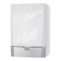
REMEHA Quinta Pro 55 Installation, User And Service Manual (89 pages)
high-efficiency wall-hung gas boiler
Table of Contents
Advertisement
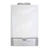
REMEHA Quinta Pro 55 Installation, User And Service Manual (88 pages)
Wall-hung gas condensing boilers
Table of Contents

REMEHA Quinta Pro 55 Installation, User And Service Manual (88 pages)
High-efficiency wall-hung gas boiler
Table of Contents
Advertisement
Advertisement