Sign In
Upload
Manuals
Brands
Remeha Manuals
Boiler
Quinta Pro 115
Remeha Quinta Pro 115 Manuals
Manuals and User Guides for Remeha Quinta Pro 115. We have
7
Remeha Quinta Pro 115 manuals available for free PDF download: Installation And Service Manual, Installation, User And Service Manual, Technical Information, Manual
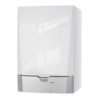
REMEHA Quinta Pro 115 Installation, User And Service Manual (89 pages)
high-efficiency wall-hung gas boiler
Brand:
REMEHA
| Category:
Boiler
| Size: 3.32 MB
Table of Contents
Contents
3
General Safety Instructions
6
Recommendations
8
Liabilities
9
About this Manual
11
Symbols Used
11
Abbreviations
11
Technical Specifications
12
Homologations
12
Technical Data
12
Certifications
12
Gas and Flue Gas Data
13
Central Heating Circuit Data
13
Electrical Data
14
Other Data
14
Technical Parameters
14
Dimensions
16
Connections
16
Electrical Diagram
17
Description of Product
18
General Description
18
Operating Principle
18
Circulating Pump
18
Main Components
19
Control Panel Description
19
Calorifer Connection
19
What each Key Means
19
Standard Delivery
20
Accessories and Options
20
Meeting of the Symbols on the Display
20
Before Installation
21
Installation Regulations
21
Choice of Location
21
Ventilation
21
Installation
22
General
22
Preparation
22
Hydraulic Connections
22
Connecting the Heating Circuit
23
Connecting the CH Flow
23
Connecting the CH Return
23
Gas Connection
24
Air Supply/Flue Gas Connections
24
Connecting the Expansion Vessel
24
Connecting the Condensate Discharge Pipe
24
Shaft Dimensions
25
Types of Flue Gas Connections
25
Minimum Dimensions of Shaft or Duct
25
Outlets
26
Material
26
Flue Gas Outlet Pipework Materials
26
Air Supply Pipework Materials
26
Length of the Air and Flue Gas Pipes
27
Room Ventilated Version
27
Room-Sealed Version
27
Maximum Chimney Length
27
Reduction Table
28
Connection in Different Pressure Areas
28
Pipe Reduction for each Element Used
28
Electrical Connections
29
Additional Guidelines
29
Connecting the Flue Gas Outlet and Air Supply
29
Control Unit
29
Access to the Connectors
31
Connection Options for the Standard PCB
32
Connecting the PWM Pump
32
Connecting the Power Supply Cable
32
Connecting the Pump
33
Connecting Modulating Thermostat
34
Connecting the On/Off Thermostat
34
Frost Protection Combined with On/Off Thermostat
35
Frost Protection Combined with Outside Sensor
35
Connecting an Outside Sensor
35
Connecting the Frost Thermostat
35
Setting the Heating Curve
36
Connecting the Calorfiler Sensor/Calorfiler Thermostat
36
Connecting a Pc/Laptop
36
Pcbs
37
Blocking Input
37
Release Input
37
Open Housing for Pcbs
37
Connection Options for the 0-10 V PCB
38
Temperature-Based Control
38
Control Based on Heat Output
38
If-01 Pcb
38
Connection Options of the PCB
39
Analogue Output
39
Control of External CH Pump
39
Control of External Three-Way Valve
39
Connection Options for the PCB
40
Control of External Gas Valve
40
Connecting the Minimum Gas Pressure Switch
40
Operation Signal and Error Messages
40
Filling the Installation
41
Water Treatment
41
Filling the Siphon
41
Filling the System
42
Comissioning
43
Gas Circuit
43
Hydraulic Circuit
43
Commissioning Procedure
43
Gas Settings
44
Adjusting to a Different Gas Type
44
Error During Start-Up Procedure
44
Operating Status
44
Checking and Setting Gas/Air Ratio
45
If Operating on Propane
45
Flue Gas Measuring Point
45
Checking/Setting Values for O2/CO2 at Full Load
46
Settting the Full Load
46
Position of Adjusting Screw a
46
Checking/Setting Values for O2/CO2 at Part Load
47
Settting the Part Load
47
Dinal Instructions
48
Position of Adjusting Screw B
48
Operation
49
Use of Control Panel
49
Shutdown
49
Frost Protection
49
Settings
51
Parameter Descriptions
51
Factory Setting
51
Changing the Parameters
53
Adjustment for Gas Type G31
53
Adjustment for Flue Gas Overpressure Cascade
53
Changing the User-Level Parameters
54
Changing the Parameters at Installer Level
54
Inputting the Access Code
54
Setting the Maximum Load for CH Operation
55
Load Quintas
55
P17 Change
56
Return to the Factory Settings
57
Carrying out an Auto-Detect
57
Displaying the Measured Values
58
Settingn the Manual Mode
58
Reading the Various Current Values
58
Reading out Hour Counter and Percentage of Successful Starts
59
Reading Current Values
59
Reading out the Hour Counter
59
Status and Sub-Status Numbers
60
Maintenance Message
62
Resetting the Service Messages
62
Setting the Installer Code
62
Standard Inspection and Maintenance Operations
63
Starting a New Service Interval
63
Checking the Water Pressure
63
Checking the Ionisation Current
64
Checking the Flue Gas Outlet/Air Supply Connections
64
Checking the Combustion
64
Checking the Automatic Air Vent
65
Cleaning the Siphon
65
Checking the Burner and Cleaning the Heat Exchanger
66
Specific Maintenance Work
67
Replacing the Ionisation/Ignition Electrode
67
Checking the Non-Return Valve
68
Reassembling the Boiler
68
Troubleshooting
69
Error Codes
69
Blocking
69
Blocking Codes
69
Lock out
71
Error Memory
75
Reading out the Error Memory
75
Clearing Error Memory
76
Disposal
77
Removal/Recycling
77
Spare Parts
78
Parts
79
Quinta Pro 30-45
79
Quinta Pro 55-65
80
Quinta Pro 90
81
Quinta Pro 115
82
Appendix
83
Erp Information
83
Product Fiche
83
Package Sheet
84
Weighing of Boilers
85
Advertisement
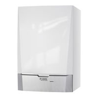
REMEHA Quinta Pro 115 Installation And Service Manual (96 pages)
Wall-hung gas condensing boilers
Brand:
REMEHA
| Category:
Boiler
| Size: 3.27 MB
Table of Contents
Eg Declaration of Conformity
2
Table of Contents
3
1 Introduction
8
Used Symbols
8
Abbreviations
8
General
8
Manufacturer's Liability
8
Installer's Liability
9
Homologations
9
Certifications
9
Device Categories
9
Additional Directives
9
Factory Test
10
2 Safety Instructions and Recommendations
11
Safety Instructions
11
Recommendations
11
3 Technical Description
13
General Description
13
Main Parts
13
Operating Principle
13
Accelerator Pump
13
System in Cascade
14
Calorifier Connection
14
Water Flow Rate
14
Technical Characteristics
14
4 Installation
17
Regulations Governing Installation
17
Package List
17
Standard Delivery
17
Accessories
17
Choice of the Location
18
Rating Plate
18
Location of the Appliance
19
Aeration
19
Main Dimensions
21
Positioning the Boiler
22
Hydraulic Connections
22
Flushing the System
22
Hydraulic Connection of the Heating Circuit
24
Connecting the Opened Expansion Vessel
25
Connecting the Condensate Discharge Pipe
25
Filling the Siphon
25
Gas Connection
26
Connections for the Air and Exhaust Pipes
26
Classification
26
Outlets
28
Lengths of the Air/Flue Gas Pipes
28
Additional Directives
29
Connection of the Combustion Gas Exhaust Pipe
30
Electrical Connections
30
Control Unit
30
Recommendations
31
Standard Control PCB
32
Connecting the Pump
34
Connecting a Third Party Control Unit
36
Connecting the Outside Temperature Sensor
37
Connect Frost Protection
38
Connecting the Calorifier Sensor/Thermostat
39
Pc/Laptop Connection
39
Shutdown Input
39
Release Input
40
Optional Electrical Connections
41
Box for the Control Pcbs
41
Connection Options for the 0-10 V Control PCB (IF-01)
42
Connection Possibilities for the PCB (SCU- S02)
43
Connection Possibilities for the PCB (SCU- S03)
45
Connection Possibilities for the PCB (SCU- X01)
45
Connection Possibilities for the PCB (SCU- X02)
46
Connection Possibilities for the PCB (SCU- X03)
47
Connection Possibilities for the PCB (C-MIX)
48
4.10 Electrical Diagram
49
4.11 Filling the System
50
Water Treatment
50
5 Start-Up
52
Control Panel
52
Functions of the Keys
52
Meaning of the Symbols on the Display
52
Check Points before Commissioning
53
Preparing the Boiler for Commissioning
53
Gas Circuit
54
Hydraulic Circuit
54
Electrical Connections
54
Checklist for Commissioning
54
Putting the Appliance into Operation
55
Gas Settings
57
Adapting to Another Gas Type
57
Setting the Air/Gas Ratio (Full Load)
58
Setting the Air/Gas Ratio (Part Load)
60
Finalizing Work
62
Reading out Measured Values
62
Reading the Various Current Values
62
Readout from the Hour Counter and Percentage of Successful Starts
63
Status and Sub-Status
64
Changing the Settings
65
Description of the Parameters
65
Modification of the User-Level Parameters
67
Modification of the Installer-Level Parameters
68
Setting the Maximum Heat Input for Central Heating Operation
69
Return to the Factory Settings "Reset Param
71
Carrying out an Auto-Detect
71
Setting the Manual Mode
72
6 Switching off the Appliance
73
Installation Shutdown
73
Antifreeze Protection
73
7 Checking and Maintenance
74
Maintenance Message
74
Preventive Maintenance with Automated "Service Message
74
Resetting the Automatic Maintenance Message
75
Dealing with the Next Maintenance Message and Starting the New Maintenance Period
75
Standard Inspection and Maintenance Operations
76
Checking the Hydraulic Pressure
76
Checking the Ionisation Current
76
Checking the Tightness of the Combusted Gases Evacuation and Air Inlet Connections
76
Checking Combustion
77
Checking the Automatic Air Vent
78
Checking the Siphon
79
Checking the Burner and Cleaning the Heat Exchanger
80
Specific Maintenance Operations
81
Inspection of the Ignition Electrode
81
Replacing the Retaining Valve
82
Assembling the Boiler
83
Checklist for Periodic Inspection and Maintenance
83
8 Troubleshooting
84
Error Codes
84
Shutdowns and Lock-Outs
87
Blockage
87
Lock-Out
87
Error Memory
89
Error Readout Memorised
90
Deletion of the Error Display
91
9 Spare Parts
92
General
92
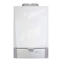
Remeha Quinta Pro 115 Installation And Service Manual (92 pages)
Wall-hung gas condensing boilers
Brand:
Remeha
| Category:
Boiler
| Size: 3.82 MB
Table of Contents
Eg Declaration of Conformity
2
Table of Contents
3
Introduction
8
Symbols Used
8
Abbreviations
8
General
8
Manufacturer's Liability
8
Installer's Liability
9
User's Liability
9
Homologations
10
Certifications
10
Equipment Categories
10
Additional Directives
10
Factory Test
10
Safety Instructions and Recommendations
11
Safety Instructions
11
Recommendations
11
Technical Description
13
General Description
13
Main Parts
13
Operating Principle
13
Shunt Pump
13
System in Cascade
14
Calorifier Connection
14
Water Flow Rate
14
Technical Specifications
14
Installation
17
Regulations Governing Installation
17
Package List
17
Standard Delivery
17
Accessories
17
Choice of the Location
18
Data Plate
18
Location of the Boiler
19
Ventilation
19
Main Dimensions
20
Positioning the Boiler
21
Hydraulic Connections
22
Flushing the System
22
Connection of the Heating Circuit
22
Connecting the Expansion Vessel
23
Connecting the Condensate Discharge Pipe
23
Gas Connection
24
Connections for the Air and Exhaust Pipes
24
Classification
24
Outlets
25
Lengths of the Air/Flue Gas Pipes
26
Additional Directives
27
Connection of the Combustion Gas Exhaust Pipe
28
Electrical Connections
28
Control Unit
28
Recommendations
29
Standard Control PCB
30
Connecting the Pump
31
Connecting a Third Party Control Unit
32
Connecting the Outside Temperature Sensor
33
Connect Frost Protection
34
Connecting the Calorifier Sensor/Thermostat
35
Pc/Laptop Connection
35
Shutdown Input
35
Release Input
36
Optional Electrical Connections
37
Box for the Control Pcbs
37
Connection Options for the 0-10 V Control PCB (IF-01)
38
Connection Possibilities for the PCB (SCU- S02)
39
Connection Possibilities for the PCB (SCU- S03)
41
Connection Possibilities for the PCB (SCU- X01)
42
Connection Possibilities for the PCB (SCU- X02)
42
Connection Possibilities for the PCB (SCU- X03)
43
Connection Possibilities for the PCB (C-MIX)
44
4.10 Electrical Diagram
45
4.11 Filling the System
46
Water Treatment
46
Filling the Siphon
46
Filling the System
47
Commissioning
48
Control Panel
48
Functions of the Keys
48
Meaning of the Symbols on the Display
48
Check Points before Commissioning
49
Preparing the Boiler for Commissioning
49
Gas Circuit
49
Hydraulic Circuit
50
Electrical Connections
50
Commissioning the Boiler
50
Gas Settings
52
Adapting to Another Gas Type
52
Setting the Air/Gas Ratio (Full Load)
53
Setting the Air/Gas Ratio (Part Load)
54
Finalizing Work
55
Reading out Measured Values
55
Reading the Various Current Values
55
Readout from the Hour Counter and Percentage of Successful Starts
56
Status and Sub-Status
57
Changing the Settings
58
Parameter Descriptions
58
Modification of the User-Level Parameters
60
Modification of the Installer-Level Parameters
60
Setting the Maximum Heat Input for Central Heating Operation
61
Return to the Factory Settings
63
Carrying out an Auto-Detect
63
Setting the Manual Mode
64
Switching off the Boiler
65
Installation Shutdown
65
Frost Protection
65
Checking and Maintenance
66
Maintenance Message
66
Preventive Maintenance with Automated Service Message
66
Resetting the Automatic Maintenance Message
67
Dealing with the Next Maintenance Message and Starting the New Maintenance Period
67
Standard Inspection and Maintenance Operations
68
Checking the Hydraulic Pressure
68
Checking the Ionization Current
68
Checking the Tightness of the Flue Gas Evacuation and Air Inlet Connections
68
Checking Combustion
69
Checking the Automatic Air Vent
70
Checking the Siphon
70
Checking the Burner and Cleaning the Heat Exchanger
71
Specific Maintenance Operations
72
Inspection of the Ignition Electrode
72
Replacing the Non-Return Valve
73
Assembling the Boiler
74
Troubleshooting
75
Error Codes
75
Shutdowns and Lock-Outs
78
Blockage
78
Lock-Out
78
Error Memory
80
Error Readout Memorised
81
Deletion of the Error Display
82
Spare Parts
83
General
83
10 Checklists
88
10.1 Checklist for Commissioning
88
10.2 Checklist for Periodic Inspection and Maintenance
89
Advertisement
REMEHA Quinta Pro 115 Installation, User And Service Manual (88 pages)
Wall-hung gas condensing boilers
Brand:
REMEHA
| Category:
Boiler
| Size: 4.36 MB
Table of Contents
Table of Contents
3
1 Safety
6
General Safety Instructions
6
Recommendations
7
Liabilities
8
Manufacturer's Liability
8
Installer's Liability
9
User's Liability
9
2 About this Manual
10
Symbols Used
10
Symbols Used in the Manual
10
Afkortingen
10
3 Technical Specifications
11
Homologations
11
Certifications
11
Unit Categories
11
Directives
11
Factory Test
11
Technical Data
11
Dimensions and Connections
14
Electrical Diagram
15
4 Description of the Product
16
General Description
16
Operating Principle
16
Circulating Pump
16
Cascade System
16
Water Flow
16
Calorifier Connection
16
Main Components
17
Control Panel Description
17
What each Key Means
17
Meaning of the Symbols on the Display
17
Standard Delivery
18
Accessories and Options
18
5 Before Installation
19
Installation Regulations
19
Choice of the Location
19
Type Plate
19
Boiler Position
20
Ventilation
20
6 Installation
21
General
21
Preparation
21
Positioning the Boiler
21
Water Connections
21
Rinsing the System
21
Connecting the Heating Circuit
22
Connecting the Expansion Vessel
22
Connecting the Condensate Discharge Pipe
23
Gas Connection
23
Air Supply/Flue Gas Connections
23
Classification
23
Outlets
25
Material
25
Length of the Air and Flue Gas Pipes
26
Additional Guidelines
27
Connecting the Flue Gas Outlet and Air Supply
28
Electrical Connections
28
Control Unit
28
Recommendations
29
Access to the Connectors
30
Connection Options for the Standard PCB
31
Pcbs
36
Filling the System
40
Water Treatment
40
Filling the Siphon
40
7 Commissioning
42
General
42
Gas Circuit
42
Hydraulic Circuit
42
Electrical Connections
42
Commissioning Procedure
42
Gas Settings
43
Adaptation to a Different Gas Type
43
Checking and Setting the Gas/Air Ratio
44
Final Instructions
46
8 Operation
47
Use of the Control Panel
47
Shutdown
47
Frost Protection
47
9 Settings
48
Parameter Descriptions
48
Changing the Parameters
50
Changing the User-Level Parameters
50
Changing the Parameters at Installer Level
51
Setting the Maximum Load for CH Operation
51
Return to the Factory Settings
53
Carrying out an Auto-Detect
53
Setting the Manual Mode
54
Displaying the Measured Values
54
Reading the Various Current Values
54
Reading out the Hour Counter and Percentage of Successful Starts
55
Status and Sub-Status
56
10 Maintenance
58
General
58
Service Message
58
Resetting the Service Messages
58
Starting a New Service Interval
59
Standard Inspection and Maintenance Operations
59
Checking the Water Pressure
59
Checking the Ionisation Current
60
Checking the Flue Gas Outlet/Air Supply Connections
60
Checking the Combustion
60
Checking the Automatic Air Vent
61
Cleaning the Siphon
62
Checking the Burner and Cleaning the Heat Exchanger
63
Specific Maintenance Work
64
Replacing the Ionisation/Ignition Electrode
64
Checking the Non-Return Valve
65
Reassembling the Boiler
65
11 Troubleshooting
66
Error Codes
66
Blocking
66
Lock out
67
Error Memory
71
Reading out the Error Memory
72
Clearing Error Memory
73
12 Disposal
74
Removal/Recycling
74
13 Spare Parts
75
General
75
Parts
76
14 Appendix
80
Erp Information
80
Product Card
80
Package Sheet
81
EC Declaration of Conformity
82
Optional Electrical Connections
82
Housing for Pcbs
82
Connection Options for the PCB (SCU-S03)
83
Connection Options for the PCB (SCU-X02)
83
Connection Options for the PCB (SCU-X03)
84
Connection Options for the PCB (C-MIX)
85
REMEHA Quinta Pro 115 Installation, User And Service Manual (88 pages)
High-efficiency wall-hung gas boiler
Brand:
REMEHA
| Category:
Boiler
| Size: 4.48 MB
Table of Contents
Table of Contents
3
1 Safety
6
General Safety Instructions
6
Recommendations
8
Liabilities
10
Manufacturer's Liability
10
Installer's Liability
10
User's Liability
10
2 About this Manual
11
Symbols Used
11
Symbols Used in the Manual
11
Abbreviations
11
3 Technical Specifications
12
Homologations
12
Certifications
12
Unit Categories
12
Directives
12
Factory Test
12
Technical Data
13
Dimensions and Connections
16
Electrical Diagram
17
4 Description of the Product
18
General Description
18
Operating Principle
18
Circulating Pump
18
Cascade System
18
Water Flow
18
Calorifier Connection
19
Main Components
19
Control Panel Description
19
What each Key Means
19
Meaning of the Symbols on the Display
20
Standard Delivery
20
Accessories and Options
20
5 Before Installation
21
Installation Regulations
21
Choice of the Location
21
Type Plate
21
Boiler Position
21
Ventilation
21
6 Installation
22
General
22
Preparation
22
Positioning the Boiler
22
Hydraulic Connections
22
Rinsing the System
22
Connecting the Heating Circuit
23
Connecting the Expansion Vessel
23
Connecting the Condensate Discharge Pipe
24
Gas Connection
24
Air Supply/Flue Gas Connections
24
Classification
25
Material
26
Dimensions of Flue Gas Outlet Pipe
27
Length of the Air and Flue Gas Pipes
27
Additional Guidelines
29
Connecting the Flue Gas Outlet and Air Supply
30
Electrical Connections
30
Control Unit
30
Recommendations
31
Access to the Connectors
31
Connection Options for the Standard PCB
32
Pcbs
37
Filling the Installation
41
Water Quality and Water Treatment
41
Filling the Siphon
41
Filling the System
41
7 Commissioning
43
General
43
Gas Circuit
43
Hydraulic Circuit
43
Electrical Connections
43
Commissioning Procedure
43
Gas Settings
44
Adjusting to a Different Gas Type
44
Checking and Setting the Gas/Air Ratio
45
Final Instructions
48
8 Operation
49
Use of the Control Panel
49
Shutdown
49
Frost Protection
49
9 Settings
51
Parameter Descriptions
51
Changing the Parameters
53
Changing the User-Level Parameters
54
Changing the Parameters at Installer Level
54
Setting the Maximum Load for CH Operation
55
Return to the Factory Settings
57
Carrying out an Auto-Detect
57
Setting the Manual Mode
58
Displaying the Measured Values
58
Reading the Various Current Values
58
Reading out the Hour Counter and Percentage of Successful Starts
59
Status and Sub-Status
60
10 Maintenance
62
General
62
Maintenance Message
62
Resetting the Service Messages
62
Starting a New Service Interval
63
Standard Inspection and Maintenance Operations
63
Checking the Water Pressure
63
Checking the Ionisation Current
64
Checking the Flue Gas Outlet/Air Supply Connections
64
Checking the Combustion
64
Checking the Automatic Air Vent
65
Cleaning the Siphon
65
Checking the Burner and Cleaning the Heat Exchanger
66
Specific Maintenance Work
67
Replacing the Ionisation/Ignition Electrode
67
Checking the Non-Return Valve
68
Reassembling the Boiler
68
11 Troubleshooting
69
Error Codes
69
Blocking
69
Lock out
71
Error Memory
75
Reading out the Error Memory
75
Clearing Error Memory
76
12 Disposal
77
Removal/Recycling
77
13 Spare Parts
78
General
78
Parts
79
14 Appendix
83
Erp Information
83
Product Fiche
83
Package Sheet
84
EC Declaration of Conformity
85
Optional Electrical Connections
85
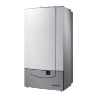
REMEHA Quinta Pro 115 Technical Information (68 pages)
High-efficiency condensing boiler for wall mounted installation Output: 18 - 115 kW
Brand:
REMEHA
| Category:
Boiler
| Size: 1.51 MB
Table of Contents
Remeha Quinta
1
Technical Information
1
Table of Contents
2
DHW Temperature Set Point
3
Preface
5
1 General Description of the Boiler
6
2 Construction
7
Boiler Layout
7
Operating Principle
8
3 Technical Data and Dimensions
9
Dimensions
9
Technical Data
10
General Specification
11
Options
12
4 Efficiency Information
12
Annual Efficiency
12
Heat to Water Efficiency
12
5 Application Information
12
6 Control and Safety Equipment
13
The Control Panel
13
General
13
Layout of the Control Panel
13
Combined Key Functions (in Operating Mode Only)
14
Display of Values with more than Two Digits
15
Flow Diagram Control System
16
Operating Mode (X
18
Shut-Off Mode (Bxx)
19
Setting Mode User Level (X
20
Flow Temperature Set Point (!)
21
Pump Run on Time HTG (@)
21
Boiler Control Setting (A)
22
Setting Mode Service Level (X00)
23
Flow Temperature Set Point During Forced Part Load ($)
25
High Limit Thermostat (%)
25
Fan Speed at Full Load HTG (^)
25
Fan Speed at Part Load (HTG and DHW - &)
25
Starting Point Modulation (*)
25
Interface Selection (()
26
DHW Cut-In Temperature (B)
26
Fan Speed at DHW Full Load (C)
26
Forced Part Load Time after Start (HTG Only - G)
26
DHW Control Stop Set Point (I)
27
DHW Control Option (J)
27
HTG Cut in Temp (N)
27
Boiler Type (P)
27
Maximum Delay Time (U)
27
Start and End Point Analog Signal (Q and Y)
27
Read-Out Mode (X00)
28
Fan Speed Mode (<00)
28
Failure Mode (X00)
29
7 Installation Instructions
30
General
30
Location
30
Flue Gas Discharge and Air Supply
31
General
31
Classification Due to Discharging Flue Gases
32
Material and Installation
33
Single Boiler Conventional Flue
33
Single Boiler, Room Sealed Flue
34
Different Pressure Zones
35
Hydraulic Installation
36
Condensate and AAV Discharge
36
Water Treatment
36
Cold Feed and Expansion Tank Height for Open Vented Systems
38
Safety Valve
38
Gas Connection
38
System Pump
38
Waterflow
38
Modular Installations
38
Introduction
38
The Remeha Quinta Cascade System
39
Independent Installation
39
DHW Production
39
8 Electrical Installation
42
General
42
Specifications
42
Electrical Supply
42
Control Box
42
Fuse Specification
42
Boiler Temperature Control
43
High Limit Temperature Protection
43
Low-Water Protection (Flow and Content)
43
External Connections
43
Boiler Control
44
Modulating Controls General (Two Wire Control)
44
Analog Control (0 -10 V DC)
45
On / off Control (1 X no Volt Switched Pair)
47
High / Low Control (2 X no Volt Switched Pairs)
47
DHW Control (Broag Priority)
47
Temperature Control
47
Primary Flow Control
47
System Pump
47
Frost Protection
47
Remote Alarm and Boiler Run Indication
48
Safety Interlock
48
Wiring Diagram
49
9 Commissioning
50
Putting the Boiler into Operation
50
Shut-Down
53
Temporary Shut-Down with Frost Protection
53
Permanent Shut-Down Without Frost Protection
53
10 Fault-Finding
54
General (All Installations)
54
Fault Codes
55
11 Inspection and Servicing Instructions
58
General
58
Annual Inspection
58
Maintenance
60
Cleaning the Fan
60
Cleaning the Venturi
60
Cleaning the Heat Exchanger
60
Cleaning the Burner Assembly
61
Cleaning the Siphon
61
Cleaning/Replacing the Ignition/Ionisation Electrode
61
Cleaning to Inspection Glass
61
REMEHA Quinta Pro 115 Manual (32 pages)
Quinta Pro series. Suggested shematics with control and power wiring details
Brand:
REMEHA
| Category:
Boiler
| Size: 2.8 MB
Advertisement
Related Products
Remeha Quinta Pro 30
Remeha Quinta Pro 90
Remeha Quinta Pro 45
Remeha Quinta Pro 65
REMEHA Quinta Pro 55
Remeha Gas 610 ECO PRO-1000
Remeha Gas 610 ECO PRO-1300
Remeha Gas 610 ECO PRO-1150
REMEHA P 320-8
REMEHA P 520-23
Remeha Categories
Boiler
Thermostat
Controller
Boiler Supplies
Heat Pump
More Remeha Manuals
Login
Sign In
OR
Sign in with Facebook
Sign in with Google
Upload manual
Upload from disk
Upload from URL