Sign In
Upload
Manuals
Brands
R&S Manuals
Measuring Instruments
FSV3004
R&S FSV3004 Signal Analyzer Manuals
Manuals and User Guides for R&S FSV3004 Signal Analyzer. We have
3
R&S FSV3004 Signal Analyzer manuals available for free PDF download: User Manual, Security Procedures
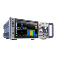
R&S FSV3004 User Manual (1268 pages)
Signal and Spectrum Analyzer
Brand:
R&S
| Category:
Measuring Instruments
| Size: 24.7 MB
Table of Contents
Table of Contents
3
1 Preface
15
About this Manual
15
Key Features
15
Conventions for Procedure Descriptions
17
Conventions Used in the Documentation
17
Notes on Screenshots
17
2 Safety Information
18
Typographical Conventions
17
3 Documentation Overview
19
Getting Started Manual
19
Service Manual
19
User Manuals and Help
19
Basic Safety Instructions
20
Data Sheets and Brochures
20
Instrument Security Procedures
20
Release Notes and Open Source Acknowledgment (OSA)
20
Application Notes, Application Cards, White Papers, Etc
21
4 Welcome to the R&S FSV/A
22
5 Getting Started
23
5.1 Preparing for Use
23
5 Getting Started
23
Preparing for Use
23
Putting into Operation
23
Windows Operating System
29
Connecting USB Devices
33
Connecting an External Monitor
35
Setting up a Network (LAN) Connection
36
Configuring the Initial Instrument Settings
41
Protecting Data Using the Secure User Mode
42
Front Panel View
44
Instrument Tour
44
Rear Panel View
53
5.3 Trying out the Instrument
57
Measuring a Basic Signal
57
Trying out the Instrument
57
Displaying a Spectrogram
59
Activating Additional Measurement Channels
61
Performing Sequential Measurements
65
Setting and Moving a Marker
66
Displaying a Marker Peak List
67
Zooming into the Display
68
Zooming into the Display Permanently
71
Saving Settings
74
Printing and Saving Results
75
Operating the Instrument
76
5.4.1 Understanding the Display Information
77
Understanding the Display Information
77
Accessing the Functionality
86
Entering Data
90
Touchscreen Gestures
94
Displaying Results
97
Getting Help
104
Remote Control
106
6 Applications, Measurement Channels
109
Available Applications
109
Amplifier
110
Fdd Bts
110
Fdd Ue
110
Spectrum
110
Analog Demodulation
111
Gsm
111
I/Q Analyzer
111
Lte
111
NB-Iot
111
R&S Multiview
112
Phase Noise
112
Pulse Measurements
112
Vector Signal Analysis (VSA)
112
Wlan
112
Selecting the Applications
113
Running a Sequence of Measurements
115
The Sequencer Concept
116
How to Set up the Sequencer
118
Sequencer Settings
118
7 Measurements and Results
120
Auto Measurements
121
Basic Measurement Types
122
Basic Measurements
122
How to Perform a Basic Sweep Measurement
123
Measurement Examples - Measuring a Sinusoidal Signal
125
Measurement Example - Measuring Levels at Low S/N Ratios
128
Measurement Examples - Measuring Signal Spectra with Multiple Signals
131
Measurement Examples in Zero Span
137
Channel Power and Adjacent-Channel Power (ACLR) Measurement
143
About Channel Power Measurements
143
Channel Power Results
144
Channel Power Basics
146
Channel Power Configuration
157
MSR ACLR Configuration
167
How to Perform Channel Power Measurements
181
Measurement Examples
186
Optimizing and Troubleshooting the Measurement
192
Reference: Predefined CP/ACLR Standards
193
Reference: Predefined ACLR User Standard XML Files
194
Carrier-To-Noise Measurements
195
About the Measurement
195
Carrier-To-Noise Results
196
Carrier-To-Noise Configuration
197
How to Determine the Carrier-To-Noise Ratio
198
Occupied Bandwidth Measurement (OBW)
199
About the Measurement
199
OBW Results
201
OBW Configuration
202
How to Determine the Occupied Bandwidth
204
Measurement Example
205
Spectrum Emission Mask (SEM) Measurement
206
About the Measurement
206
Typical Applications
206
SEM Results
207
SEM Basics
210
SEM Configuration
220
Sweep List
221
Multi-SEM (Sub Block) Settings
227
Reference Range
228
Power Classes
230
MSR Settings
231
Standard Files
234
List Evaluation (Results Configuration)
236
How to Perform a Spectrum Emission Mask Measurement
237
Measurement Example: Multi-SEM Measurement
242
Reference: SEM File Descriptions
244
Spurious Emissions Measurement
251
About the Measurement
251
Spurious Emissions Measurement Results
252
Spurious Emissions Basics
253
Spurious Emissions Measurement Configuration
255
Range Start / Range Stop
256
Detector
257
Filter Type
257
Rbw
257
Sweep Time
257
Sweep Time Mode
257
Vbw
257
Preamp
258
Reference Level
258
RF Attenuation
258
RF Attenuation Mode
258
Stop after Sweep
258
Sweep Points
258
Transducer
258
Abs Limit Start / Abs Limit Stop
259
Delete Range
259
Insert before Range / Insert after Range
259
Limit Check
259
List Evaluation State/Show Peaks
260
List Evaluation State
260
Margin
260
Show Peaks
260
Details
261
How to Perform a Spurious Emissions Measurement
261
Peaks Per Range
261
Save Evaluation List
261
Reference: ASCII Export File Format (Spurious)
263
Statistical Measurements (APD, CCDF)
264
About the Measurements
264
APD and CCDF Results
265
Typical Applications
265
APD and CCDF Basics - Gated Triggering
267
APD and CCDF Configuration
269
How to Perform an APD or CCDF Measurement
275
Examples
276
About the Measurement
279
Optimizing and Troubleshooting the Measurement
279
Time Domain Power Measurement
279
Time Domain Power Results
279
Time Domain Power Basics - Range Definition Using Limit Lines
280
Time Domain Power Configuration
281
How to Measure Powers in the Time Domain
283
Measurement Example
283
7.10 Harmonic Distortion Measurement
285
About the Measurement
285
Harmonic Distortion Measurement
285
Harmonic Distortion Basics
286
Harmonic Distortion Results
288
Harmonic Distortion Configuration
289
How to Determine the Harmonic Distortion
291
Third Order Intercept (TOI) Measurement
291
About the TOI Measurement
292
TOI Basics
292
TOI Results
296
TOI Configuration
297
How to Determine the Third Order Intercept
298
Measurement Example - Measuring the R&S Fsv/A's Intrinsic Intermodulation
299
AM Modulation Depth Measurement
301
About the Measurement
301
AM Modulation Depth Configuration
302
AM Modulation Depth Results
302
How to Determine the am Modulation Depth
304
8 Common Measurement Settings
305
Optimizing and Troubleshooting the Measurement
304
Configuration Overview
305
Data Input and Output
307
Receiving Data Input and Providing Data Output
307
Input Source Settings
311
Radio Frequency State/Input Coupling
312
Input Coupling
312
Radio Frequency State
312
Direct Path
313
Impedance
313
YIG-Preselector
313
Preselector Adjust
314
Power Sensors
316
Optional External Generator Control
325
Output Settings
351
If/Video Output
352
Audio Output
353
Trigger Input/Output Settings
355
How to Output a Trigger Signal
357
Frequency and Span Configuration
358
Impact of the Frequency and Span Settings
358
Frequency and Span Settings
360
Keeping the Center Frequency Stable - Signal Tracking
364
How to Define the Frequency Range
365
How to Move the Center Frequency through the Frequency Range
365
Amplitude and Vertical Axis Configuration
366
Impact of the Vertical Axis Settings
366
Amplitude Settings
369
Scaling the Y-Axis
373
How to Optimize the Amplitude Display
375
Bandwidth, Filter and Sweep Configuration
376
Impact of the Bandwidth, Filter and Sweep Settings
376
Bandwidth, Filter and Sweep Settings
382
Reference: List of Available RRC and Channel Filters
389
Trigger and Gate Configuration
391
Triggering
392
Gating
402
Adjusting Settings Automatically
409
Result Display Configuration
412
9 Common Analysis and Display Functions
412
Basic Evaluation Methods
412
Laying out the Result Display with the Smartgrid
415
Zoomed Displays
419
Single Zoom Versus Multiple Zoom
419
Zoom Functions
421
How to Zoom into a Diagram
423
Marker Usage
426
Basics on Markers
426
Marker Settings
429
Marker Search Settings and Positioning Functions
435
Marker (Measurement) Functions
442
How to Work with Markers
463
Measurement Example: Measuring Harmonics Using Marker Functions
466
Display and Limit Lines
467
Display Lines
468
Limit Lines
470
Trace Configuration
486
Standard Traces
486
Spectrograms
498
Trace Math
516
Importing and Exporting Measurement Results for Evaluation
518
Displaying a Reference Trace - Importing Trace Data
519
Trace/Data Ex/Import
520
How to Import Traces
523
How to Export Trace Data and Numerical Results
524
How to Export a Peak List
525
Reference: ASCII File Export Format
525
10 Optimizing Measurements
526
Improving Averaging Results
526
11 Data Management
528
Minimizing the Measurement Duration
526
Restoring the Default Instrument Configuration (Preset)
528
Protecting Data Using the Secure User Mode
529
Storing and Recalling Instrument Settings and Measurement Data
531
Quick Save/Quick Recall
532
Configurable Storage and Recall
534
How to Save and Load Instrument Settings
540
Import/Export Functions
541
Creating Screenshots of Current Measurement Results and Settings
545
Print and Screenshot Settings
545
How to Store or Print Screenshots of the Display
555
Example for Storing Multiple Measurement Results to a PDF File
558
12 General Instrument Setup
561
Alignment
561
Basics on Alignment
561
Alignment Settings
563
How to Perform a Self-Test
565
How to Align the Instrument
566
How to Align the Touchscreen
566
Display Settings
567
How to Configure the Colors for Display and Printing
578
How to Work with the Soft Front Panels
579
Event-Based Actions
580
Managing Rules
581
Defining Rules
582
Debugging Rules with the EBA-Journal
588
Reference: Overview of Available Result-Events
589
Application Starter
590
Configuration
590
Basics on Transducer Factors
592
How to Work with the Application Starter
592
Transducers
592
Transducer Settings
594
Reference: Transducer Factor File Format
599
How to Configure the Transducer
600
Basics on Frequency Response Correction
604
Frequency Response Correction (R&S FSV/A-K544)
604
User-Defined Frequency Response Correction Settings
607
Reference Frequency Settings
614
Hardware Information
617
System Configuration Settings
617
Information on Versions and Options
618
System Messages
619
Firmware Updates
620
General Configuration Settings
622
Signal Generator Settings
624
Service Functions
625
R&S Support Information
626
Self-Test Settings and Results
627
Calibration Signal Display
628
Service Functions
629
Hardware Diagnostics
631
General Parameter Coupling
632
Synchronizing Measurement Channel Configuration
632
User-Defined Parameter Coupling
634
Generator Coupling
637
How to Synchronize Parameters
640
Example for a User-Defined Parameter Coupling
641
13 Network and Remote Operation
644
Remote Control Basics
644
Remote Control Interfaces and Protocols
644
SCPI (Standard Commands for Programmable Instruments)
653
Messages
654
VISA Libraries
654
SCPI Command Structure
655
Command Sequence and Synchronization
663
Status Reporting System
665
General Programming Recommendations
682
GPIB Languages
683
The IECWIN Tool
685
Automating Tasks with Remote Command Scripts
686
The Context-Sensitive SCPI Command Menu
687
The SCPI Recorder
689
How to Determine the Required SCPI Command
692
How to Create and Export SCPI Scripts
693
Example for a Recorded SCPI Script
695
Network and Remote Control Settings
696
General Network Settings
697
Remote Settings
699
Compatibility Settings
702
LXI Settings
705
Remote Errors
707
Returning to Manual Mode ("Local")
709
How to Configure a Network
710
How to Set up a Network and Remote Control
710
How to Log on to the Network
717
How to Operate the Instrument Without a Network
717
How to Share Directories (Only with Microsoft Networks)
719
How to Control the R&S FSV/A Via the Web Browser Interface
720
How to Deactivate the Web Browser Interface
721
How to Set up Remote Desktop
722
How to Start a Remote Control Session from a PC
728
How to Return to Manual Operation
729
14 Remote Commands
730
Conventions Used in SCPI Command Descriptions
730
Common Commands
731
Common Suffixes
731
Selecting the Mode and Applications
736
Selecting the Operating Mode and Application
736
Performing a Sequence of Measurements
740
Programming Example: Performing a Sequence of Measurements
742
Configuring and Performing Measurements
744
Performing Measurements
745
Configuring Power Measurements
748
Measuring the Channel Power and ACLR
752
Measuring the Carrier-To-Noise Ratio
788
Measuring the Occupied Bandwidth
789
Measuring the Spectrum Emission Mask
791
Measuring Spurious Emissions
826
Analyzing Statistics (APD, CCDF)
838
Measuring the Time Domain Power
848
Measuring the Harmonic Distortion
858
Measuring the Third Order Intercept Point
861
Measuring the am Modulation Depth
864
List Evaluations
866
Measuring the Pulse Power
870
Configuring the Result Display
875
General Window Commands
875
Working with Windows in the Display
876
Examples: Configuring the Result Display
882
Defining the Frequency and Span
885
Setting Basic Measurement Parameters
885
Configuring Bandwidth and Sweep Settings
891
Configuring the Vertical Axis (Amplitude, Scaling)
898
Configuring Triggered and Gated Measurements
908
Adjusting Settings Automatically
919
Configuring the Data Input and Output
921
Analyzing Measurements (Basics)
955
Zooming into the Display
955
Configuring the Trace Display and Retrieving Trace Data
959
Working with Markers
982
Configuring Display and Limit Lines
1040
Managing Settings and Results
1059
General Data Storage and Loading Commands
1060
Selecting the Items to Store
1066
Storing and Loading Instrument Settings
1069
Storing or Printing Screenshots
1074
Storing Measurement Results
1085
Examples: Managing Data
1087
Configuring the R&S FSV/A
1090
Configuring the Reference Frequency
1091
Calibration and Checks
1093
Working with Transducers
1097
Compensating for Frequency Response Using Touchstone Files (R&S FSV/A-K544)
1101
Customizing the Screen Layout
1116
Configuring the Network and Remote Control
1123
Remote Commands for Language Settings
1123
Checking the System Configuration
1128
Signal Generator Control Commands
1134
Using Service Functions
1135
Remote Commands for Synchronizing Parameters
1137
Using the Status Register
1152
General Status Register Commands
1153
Reading out the Condition Part
1153
Controlling the Enable Part
1154
Reading out the Event Part
1154
Controlling the Negative Transition Part
1155
Commands for Remote Instrument Operation
1156
Controlling the Positive Transition Part
1156
Emulating Other Instruments' Commands
1157
Setting up Instrument Emulation
1157
Reference: GPIB Commands of Emulated HP Models
1160
Reference: Command Set of Emulated PSA Models
1189
Reference: Command Set of Emulated PXA Models
1193
Deprecated Commands
1195
Programming Examples
1198
Programming Example: Performing a Basic Frequency Sweep
1199
Service Request
1202
15 Maintenance
1211
Cleaning
1211
16 Troubleshooting
1213
Error Information
1213
Error Messages in Remote Control Mode
1214
Troubleshooting Remote Operation
1215
Miscellaneous Troubleshooting Hints
1217
Collecting Information for Support
1218
List of Remote Commands (Base Unit)
1221
Index
1243
Advertisement
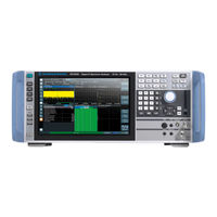
R&S FSV3004 User Manual (307 pages)
I/Q Analyzer and I/Q Input Interfaces
Brand:
R&S
| Category:
Measuring Instruments
| Size: 5.98 MB
Table of Contents
Table of Contents
3
1 Preface
5
Documentation Overview
5
About this Manual
7
Conventions Used in the Documentation
8
2 Welcome to the I/Q Analyzer Application
9
Starting the I/Q Analyzer Application
9
Understanding the Display Information
10
3 Measurement and Result Displays
13
Magnitude
13
Spectrum
13
I/Q-Vector
14
Marker Peak List
15
Marker Table
15
Real/Imag (I/Q)
15
4 Basics on I/Q Data Acquisition and Processing
17
Processing Analog I/Q Data from RF Input
17
Using Probes
21
4.3 Basics on External Generator Control
24
Basics on External Generator Control
24
External Generator Connections
24
Overview of Supported Generators
27
Generator Setup Files
28
Calibration Mechanism
29
Normalization
29
Reference Trace, Reference Line and Reference Level
31
Coupling the Frequencies
31
Displayed Information and Errors
34
Basics on Input from I/Q Data Files
35
IF and Video Signal Output
36
Receiving and Providing Trigger Signals
36
I/Q Data Import and Export
37
Basics on FFT
38
5 Configuration
45
Configuration Overview
45
Import/Export Functions
47
Data Input and Output Settings
50
5.4 Amplitude
65
Amplitude
65
Reference Level
66
Shifting the Display ( Offset )
66
Unit
66
Setting the Reference Level Automatically ( Auto Level )
67
RF Attenuation
67
Attenuation Mode / Value
67
Using Electronic Attenuation
67
Input Settings
68
Preamplifier
68
Frequency Settings
70
Trigger Settings
71
Trigger Source
72
Trigger Source
73
Free Run
73
External Trigger 1/2
73
IF Power
73
I/Q Power
74
Time
74
Drop-Out Time
74
Repetition Interval
74
Trigger Level
74
Hysteresis
75
Trigger Holdoff
75
Trigger Offset
75
Data Acquisition and Bandwidth Settings
77
5.7.1 Data Acquisition
78
Analysis Bandwidth
79
Maximum Bandwidth
79
Meas Time
79
Record Length
79
Sample Rate
79
Rbw
80
Swap I/Q
80
Advanced FFT Mode / Basic Settings
81
Transformation Algorithm
81
FFT Length
81
Window Function
81
Window Overlap
81
Window Length
81
Adjusting Settings Automatically
85
6 Analysis
89
Display Configuration
85
Trace Settings
89
Spectrogram Settings
93
Trace / Data Export Configuration
97
Section 8
98
Export All Traces and All Table Results
98
Include Instrument & Measurement Settings
98
Decimal Separator
99
Export Trace to ASCII File
99
Trace to Export
99
Export Spectrogram to ASCII File
100
Marker Usage
100
File Type
100
Decimal Separator
100
Section 9
102
Frame (Spectrogram Only)
102
Marker Position X-Value
102
Marker State
102
Marker Type
102
Selected Marker
102
Assigning the Marker to a Trace
103
Linking to Another Marker
103
Reference Marker
103
Select Marker
103
All Marker off
104
7 How to Work with I/Q Data
125
How to Export and Import I/Q Data
125
How to Perform Measurements in the I/Q Analyzer Application
125
Introduction
128
Common Suffixes
133
Activating I/Q Analyzer Measurements
134
Configuring I/Q Analyzer Measurements
139
8 Remote Commands to Perform Measurements with I/Q Data
128
Syst:comm:rdev:pmet2:Def '','Nrp-Z81',''
161
Calculate<N>:Pmeter<P>:Relative:state
162
[Sense:]Pmeter<P>:Dcycle:value
163
[Sense:]Pmeter<P>:Dcycle[:State]
163
[Sense:]Pmeter<P>:Frequency
163
[Sense:]Pmeter<P>:Frequency:link
164
[Sense:]Pmeter<P>:Mtime
164
[Sense:]Pmeter<P>:Mtime:average:count [Sense:]Pmeter<P>:Mtime:average[:State] [Sense:]Pmeter<P>:Roffset[:State]
165
Unit<N>:Pmeter<P>:Power
166
Unit<N>:Pmeter<P>:Power:ratio
166
[Sense:]Pmeter<P>:Update[:State]
166
[Sense:]Pmeter<P>[:State]
166
Configuring the Result Display
202
Capturing Data and Performing Sweeps
210
I/Q Analysis
216
Table of Contents
242
Calculate<N>:Marker<M>:Maximum:left
251
Calculate<N>:Marker<M>:Maximum:next
252
Calculate<N>:Marker<M>:Maximum:right
252
Calculate<N>:Marker<M>:Maximum[:Peak]
252
Calculate<N>:Marker<M>:Minimum:left
253
Calculate<N>:Marker<M>:Minimum:next
253
Calculate<N>:Marker<M>:Minimum:right
254
Retrieving Results
264
Importing and Exporting I/Q Data and Results
275
Calculate<N>:Marker<M>:Minimum[:Peak]
254
Programming Examples
276
Deprecated Commands
279
Annex
281
A Formats for Returned Values: ASCII Format and Binary Format
283
B Reference: Format Description for I/Q Data Files
284
C I/Q Data File Format (Iq-Tar)
286
I/Q Parameter XML File Specification
287
I/Q Data Binary File
290
List of Commands (I/Q Analyzer)
292
Index
300
R&S FSV3004 Security Procedures (13 pages)
Signal and Spectrum Analyzer Instrument Security Procedures
Brand:
R&S
| Category:
Measuring Instruments
| Size: 0.84 MB
Table of Contents
Table of Contents
3
Overview
3
Instrument Models Covered
4
Security Terms and Definitions
4
Types of Memory and Information Storage in the R&S FSV/A
5
Instrument Declassification
8
Functionality Outside the Secured Area
10
Validity of Instrument Calibration after Declassification
10
Securing Self Alignment Data When Security Write Protection Is Enabled
11
Secure User Mode
12
Special Considerations for USB Ports
12
Advertisement
Advertisement
Related Products
R&S FSV3000 Series
R&S FSV3030
R&S FSV3044
R&S FSV3007
R&S FSV3013
R&S FSVA3000 Series
R&S FSVA3007
R&S FSVA3013
R&S FSVA3030
R&S FSVA3044
R&S Categories
Measuring Instruments
Test Equipment
Portable Generator
Power Supply
Accessories
More R&S Manuals
Login
Sign In
OR
Sign in with Facebook
Sign in with Google
Upload manual
Upload from disk
Upload from URL