Sign In
Upload
Manuals
Brands
PRECITEC Manuals
Cutter
Lasermatic LightCutter
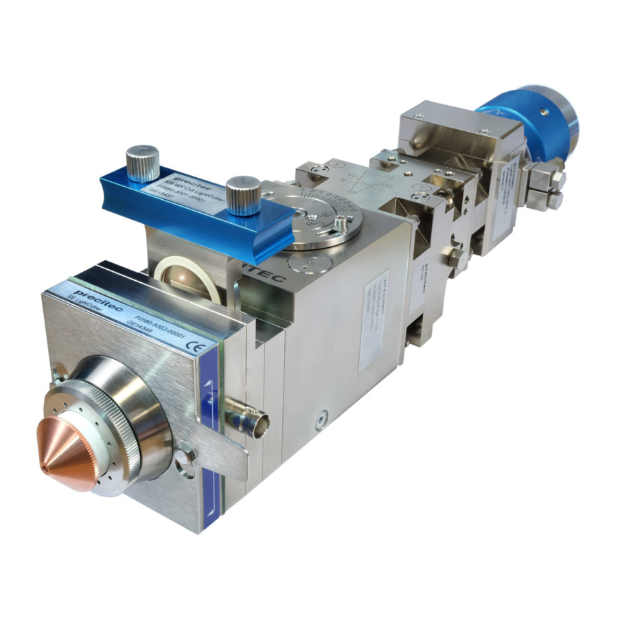
PRECITEC Lasermatic LightCutter Manuals
Manuals and User Guides for PRECITEC Lasermatic LightCutter. We have
1
PRECITEC Lasermatic LightCutter manual available for free PDF download: Operating Instructions Manual
PRECITEC Lasermatic LightCutter Operating Instructions Manual (82 pages)
Cutting head for fibre-coupled lasers
Brand:
PRECITEC
| Category:
Cutter
| Size: 4.53 MB
Table of Contents
Table of Contents
5
Fig. 5-2 Maintenance: Ceramic Part, Nozzle
9
Fig. 5-6 Maintenance: Sensor Insert
9
Fig. 5-7 Maintenance: Sensor Insert
9
1 Basic Safety Notes
11
Warranty and Liability
11
Meaning of Symbols and Notes
11
Intended Use
13
Basic Standards
13
Obligations of Operator and Personnel
14
Normal Operation Safety Measures
14
Protection against Electric Shock
14
Risk of Injury from Moving Parts
15
Risk of Injury from Explosion
15
Risk of Injury from Laser Radiation
15
Residual Risk from Uncontrolled Laser Beam Escape (Angled Laser Head)
16
Corrosion in the Water Cooling Circuit
16
Noise Occurring During the Laser Cutting Process
17
Storage and Transport
17
What to Do in Emergency Situations
17
Fig. 2-1 Laser Head, Overall View
18
Design and Functions
19
Distance Controller
20
Protective Equipment
20
Technical Specifications
21
Specific Versions (Focal Lengths, Collimators)
22
2 Product Description
18
Product - Overall View
18
Fig. 2-2 Specific Versions
22
Straight Versions
23
Focal Lengths 100/125
23
Fig. 2-3 Mechanical Dimensions, Focal Lengths 100/125
23
Focal Length 150
24
Fig. 2-4 Mechanical Dimensions, Focal Length 150
24
Focal Length 200
25
Fig. 2-5 Mechanical Dimensions, Focal Length 200
25
Straight Versions
26
Focal Lengths 100/125
26
Fig. 2-6 Mechanical Dimensions, Focal Lengths 100/125
26
Focal Length 150
27
Fig. 2-7 Mechanical Dimensions, Focal Length 150
27
Focal Length 200
28
Fig. 2-8 Mechanical Dimensions, Focal Length 200
28
Angled Versions (Dimensions, Angled Design)
29
Fig. 2-9 Mechanical Dimensions (Angled)
29
Media Connections
30
Fig. 2-10 Media Connections, Laser Head
30
Lightcutter 3D Version
31
Fig. 2-11 Cutting Head, View
31
Accessories
32
Analysing Electronics (EG8030)
32
Optics Service Case (Storage Box)
32
Fig. 2-12 Accessories: Adjust Box EG8030
32
Fig. 2-13 Accessories: Optics Service Case
32
3 Fitting and Installing
33
Safety Notes
33
Checking Package Contents
34
Fitting
35
Fitting the Ceramic Part and Nozzle (Only in the Case of Individual Parts Delivery)
35
Fig. 3-1 Fitting: Ceramic Part, Nozzle
35
Connecting the Laser Fibre to the Laser Head
36
Fig. 3-2 Fitting: Laser Fibre
36
Fig. 3-3 Fitting: Sealing the Fibre Coupling
37
Fitting the Cutting Head to the Machine
38
Fig. 3-4 Fitting: Laser Head to the Machine
38
Grounding of the Laser Head
39
Checking the Protective Window COL for Contamination
40
Fig. 3-6 Fitting: Protective Window COL
40
Installation
41
Connecting the Cutting Gas System
41
Fig. 3-7 Installation: Connections - Cutting Gas
41
Connecting the Cooling Water System
42
Fig. 3-8 Installation: Water Connections
42
Connecting the Distance Sensor System
43
Fig. 3-9 Installation: Connection Diagram
43
4 Commissioning
44
Safety Notes
44
Adjusting the Laser Beam
45
Centring and Adjusting the Laser Beam
45
Fig. 4-1 Commissioning: Laser Beam - Beam Position
45
Setting the Focal Position
47
Fig. 4-2 Commissioning: Laser Beam - Focal Position
47
Fig. 4-3 Commissioning: Laser Beam - Reference Adjustment
48
Checking the Standoff Distance
49
Fig. 4-4 Commissioning: Laser Beam - Standoff Distance
49
5 Maintenance
50
Safety Notes
50
Maintenance Work (Summary)
51
Maintenance Recommendations
52
Replacing the Ceramic Part and Nozzle
53
Care and Maintenance of the Protective Window Cartridge
54
Fig. 5-3 Maintenance: Protective Window Cartridge
54
Replacing the Protective Window
55
Fig. 5-4 Maintenance: Protective Window
55
Replacing Axial Gaskets
56
Fig. 5-5 Maintenance: Seal
56
Maintaining the Sensor Insert
57
(Removing Short Circuits)
57
6 Specific Characteristics of the 3D Version
61
Lightcutter 3D
61
Product View
61
Fig. 6-1 Cutting Head, View
61
Technical Specifications
62
Fig. 6-2 Mechanical Dimensions
63
Media Connections
64
Fig. 6-3 Connections - Media Connections
64
Fig. 6-4 Installation: Ceramic Part, Nozzle
65
Installation (Integration into the Machine)
66
Connecting the Laser Fibre to the Laser Head (Trained Personnel Only)
66
Fig. 6-5 Installation: Laser Fibre
66
Fixing the Cutting Head to the Machine (Trained Personnel Only)
67
Laser Head - Hole Pattern
67
Grounding the Laser Head
68
Aligning the Sensor Insert (HF Socket, Sensor System)
69
Maintenance
70
Replacing the Ceramic Part and Nozzle (Sensor Area)
70
Maintaining and Replacing the Sensor Insert (SE)
71
Parts Available (Lightcutter 3D Only)
72
Table 6-2 Appendix: Parts Available (Lightcutter 3D)
72
7 Error Analysis and Diagnostics
73
Safety Notes
73
Malfunctions
73
Electrical Malfunctions
73
Mechanical Malfunctions
74
Table 7-2 Error Analysis: Mechanical Malfunctions
74
8 Appendix
75
Basic Technical Information
75
Conversion of Units
75
Compressed Air Quality (ISO 8573-1)
75
Cooling Water - Dew Point Temperature
75
Table 8-1 Appendix: Units - Conversion Table
75
Table 8-2 Appendix: Compressed Air Quality - Purity Classes
75
Table 8-3 Appendix: Cooling Water - Dew Point Temperature
75
Running Cables (Notes)
76
Parts Available
77
Table 8-5 Appendix: Nozzles Available
78
Advertisement
Advertisement
Related Products
PRECITEC Lasermatic LightCutter 3D
PRECITEC Categories
Measuring Instruments
Accessories
Cutter
More PRECITEC Manuals
Login
Sign In
OR
Sign in with Facebook
Sign in with Google
Upload manual
Upload from disk
Upload from URL