
Summary of Contents for PRECITEC Lasermatic LightCutter
- Page 1 LightCutter ® Lasermatic Cutting head for fibre-coupled lasers Operating Instructions © Precitec GmbH & Co. KG • EN 09/2019 D 159195...
- Page 2 Precitec or used against the due interest of Precitec. It is intended exclusively for internal use associated with setup and service work. Any other use is not permitted. Any communication of this documentation to a third party requires the prior express written permission of Precitec.
- Page 3 Date Chapter / page Topic, revision, action taken 08/2017 revision - technical data 01/2018 revision - versions 05/2018 revision - nozzle electrodes 11/2018 revision - head version 09/2019 revision D 159195 © Precitec GmbH & Co. KG • EN 09/2019...
- Page 4 Notes LightCutter Notes © Precitec GmbH & Co. KG • EN 09/2019 D 159195...
-
Page 5: Table Of Contents
Media connections 2 - 20 LightCutter 3D version 2 - 21 Accessories 2 - 22 2.9.1 Analysing electronics 2 - 22 (EG8030) 2.9.2 Optics service case 2 - 22 (storage box) D 159195 © Precitec GmbH & Co. KG • EN 09/2019... - Page 6 Maintaining the sensor insert 5 - 47 5.6.1 Cleaning the inside of the sensor insert 5 - 47 (removing short circuits) 5.6.2 Replacing the sensor insert 5 - 49 © Precitec GmbH & Co. KG • EN 09/2019 D 159195...
- Page 7 (ISO 8573-1) 8.1.3 Cooling water - Dew point temperature 8 - 65 8.1.4 Running cables 8 - 66 (notes) Parts available 8 - 67 AM YW30 CL R / P0253-1406-00001 D 159195 © Precitec GmbH & Co. KG • EN 09/2019...
- Page 8 Connections - Media connections 6 - 54 (3D version) Fig. 6-4 Installation: Ceramic part, nozzle 6 - 55 (LightCutter 3D) Fig. 6-5 Installation: Laser fibre 6 - 56 (e.g.QBH socket, 3D) viii © Precitec GmbH & Co. KG • EN 09/2019 D 159195...
-
Page 9: Fig. 5-2 Maintenance: Ceramic Part, Nozzle
6 - 59 (4x90°, 3D version) Fig. 6-10 Maintenance: Ceramic part, nozzle 6 - 60 (e.g. LightCutter 3D version) Fig. 6-11 Maintenance: Sensor insert 6 - 61 (replacement, 3D version) D 159195 © Precitec GmbH & Co. KG • EN 09/2019... - Page 10 Appendix: Compressed air quality - Purity classes 8 - 65 Table 8-3 Appendix: Cooling water - Dew point temperature 8 - 65 Table 8-4 Appendix: Parts available 8 - 67 Table 8-5 Appendix: Nozzles available 8 - 68 © Precitec GmbH & Co. KG • EN 09/2019 D 159195...
-
Page 11: Basic Safety Notes
Precitec shall not be liable for any damage or injury caused by incorrect operation or improper handling of our products / units. Dismantling the product / unit may result in warranty claims becoming null and void. - Page 12 Describes all components and conditions that have to be available Prerequisite: or fulfilled so that an action can be performed successfully. Indicates to the user that additional information on the Further information: subject is available. 1 - 2 © Precitec GmbH & Co. KG • EN 09/2019 D 159195...
-
Page 13: Intended Use
Data sheet. Any use which deviates from that which was originally intended is regarded as improper use. Precitec shall not be liable for any damage caused by the improper use of the unit. Both as a standalone device or in combination with the relevant devices and... -
Page 14: Obligations Of Operator And Personnel
Personnel must be instructed according to the regulations and safety notes and informed of potentially hazardous situations. Precitec shall not be liable for any damage caused by not complying with or having insufficient knowledge about the information contained in the operating instructions. -
Page 15: Risk Of Injury From Moving Parts
If it has been decided that safe operation is no longer possible, the product/ device must be switched off. The unit or the machine must be protected against unintended use. 1 - 5 D 159195 © Precitec GmbH & Co. KG • EN 09/2019... -
Page 16: Residual Risk From Uncontrolled Laser Beam Escape (Angled Laser Head)
Only stainless steel must not or plastic connections can be used. For pure stainless steel circuits water with a conductivity value use only prescribed by the laser manufacturer 1 - 6 © Precitec GmbH & Co. KG • EN 09/2019 D 159195... -
Page 17: Noise Occurring During The Laser Cutting Process
• Disconnect the machine from the power supply; set the main switch to AUS ('OFF') • Only use extinguishers to extinguish fires, Class B e.g. CO extinguishers (carbon dioxide) 1 - 7 D 159195 © Precitec GmbH & Co. KG • EN 09/2019... -
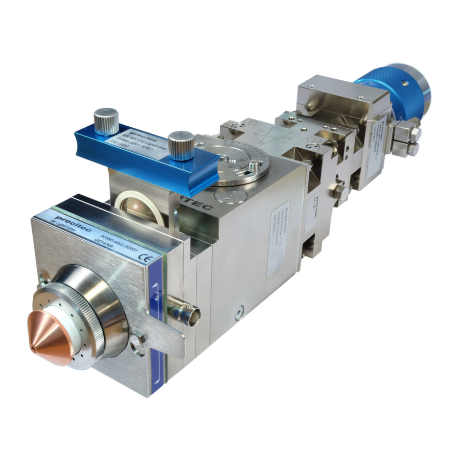
Page 18: Product Description
9 BNC connection (focal position) (sensor system) 4 G1/8 connection, left 10 Protective window cartridge (cutting gas) 5 Sensor insert 11 Beam bender module (COL 90°) 6 Nut 2 - 8 © Precitec GmbH & Co. KG • EN 09/2019 D 159195... -
Page 19: Design And Functions
Fittings with M5 threaded holes for hoses (ø6 mm external/ are used for cooling water outflow and inflow. ø4 mm internal) Precitec offers fibre sockets for its high-performance collimators for connecting conventional fibre optic cables can also be equipped with a protective Collimators OG-COL (straight design) -
Page 20: Distance Controller
The nozzle is screwed into the ceramic part and can be replaced easily if Nozzle (nozzle electrode) worn. Precitec nozzles and ceramic parts are very precisely worked. Because of the minimum concentricity tolerance any re-adjustment work can be reduced or avoided when replacing these parts. -
Page 21: Technical Specifications
0.12 at F max. 0.16 at F External acceleration max. 30 m/s (laser head) Precitec does not permit the recommended maximum acceleration values for the laser head integrated in the laser cutting machine to be exceeded. Jolt max. 1000 m/s (laser head) Focal length –... -
Page 22: Specific Versions (Focal Lengths, Collimators)
R Aperture adapter (rotating) (AM YW30 CL R) For detailed information on the spare parts that can be supplied, please refer to chapter 8.2 „Parts available“, page 8-67. 2 - 12 © Precitec GmbH & Co. KG • EN 09/2019 D 159195... -
Page 23: Straight Versions
Straight versions without protective window COL (dimensions/ straight design) 2.4.1 Focal lengths 100/125 * Length depends on the fibre socket (LightCutter version) Fig. 2-3 Mechanical dimensions, focal lengths 100/125 (straight) 2 - 13 D 159195 © Precitec GmbH & Co. KG • EN 09/2019... -
Page 24: Focal Length 150
2.4 Straight versions without protective window COL (dimensions/ straight design) LightCutter 2.4.2 Focal length 150 * Length depends on the fibre socket (LightCutter version) Fig. 2-4 Mechanical dimensions, focal length 150 (straight) 2 - 14 © Precitec GmbH & Co. KG • EN 09/2019 D 159195... -
Page 25: Focal Length 200
2 Product description 2.4.3 Focal length 200 * Length depends on the fibre socket (LightCutter version) Fig. 2-5 Mechanical dimensions, focal length 200 (straight) 2 - 15 D 159195 © Precitec GmbH & Co. KG • EN 09/2019... -
Page 26: Straight Versions
(dimensions/ straight design) 2.5.1 Focal lengths 100/125 * Length depends on the fibre socket (LightCutter version) Fig. 2-6 Mechanical dimensions, focal lengths 100/125 (straight with OG-COL) 2 - 16 © Precitec GmbH & Co. KG • EN 09/2019 D 159195... -
Page 27: Focal Length 150
2 Product description 2.5.2 Focal length 150 * Length depends on the fibre socket (LightCutter version) Fig. 2-7 Mechanical dimensions, focal length 150 (straight with OG-COL) 2 - 17 D 159195 © Precitec GmbH & Co. KG • EN 09/2019... -
Page 28: Focal Length 200
2.5 Straight versions with protective window COL (dimensions/ straight design) LightCutter 2.5.3 Focal length 200 * Length depends on the fibre socket (LightCutter version) Fig. 2-8 Mechanical dimensions, focal length 200 (straight with OG-COL) 2 - 18 © Precitec GmbH & Co. KG • EN 09/2019 D 159195... -
Page 29: Angled Versions (Dimensions, Angled Design)
Fig. 2-9 Mechanical dimensions (angled) Cutting head 90° (L)/(R) [mm] LightCutter/ F100, 125 with F 220.6 LightCutter/ F150 with F 257.9 LightCutter/ F200 with F 295.3 2 - 19 D 159195 © Precitec GmbH & Co. KG • EN 09/2019... -
Page 30: Media Connections
Attention – Media connections! Please note the connection dimensions and the permitted maximum pressure load on the media connections (cutting gas and water cooling circuit) Tab. 2-1, page 2-11. 2 - 20 © Precitec GmbH & Co. KG • EN 09/2019 D 159195... -
Page 31: Lightcutter 3D Version
(sensor system) sensor insert can be aligned 4 x 90° using the connecting holes on the laser head (bottom) 2 - 21 D 159195 © Precitec GmbH & Co. KG • EN 09/2019... -
Page 32: Accessories
The optics service case is used to store replacement optics and accessories required for the care and (cleaning materials, protective covers, auxiliary tools) maintenance of the beam shaping optics (P0001-000-Q0002). 2 - 22 © Precitec GmbH & Co. KG • EN 09/2019 D 159195... -
Page 33: Fitting And Installing
Any repair work and any work relating to troubleshooting require special Personnel requirements knowledge and must only be carried out by trained specialist staff. Precitec shall not be liable for any damage caused by not complying with or having insufficient knowledge about the information contained in the operating instructions. -
Page 34: Checking Package Contents
The laser head's functional efficiency must always be guaranteed to avoid any accidents. If damaged, the laser head must be protected against accidental use. Damaged parts must be replaced. 3 - 24 © Precitec GmbH & Co. KG • EN 09/2019 D 159195... -
Page 35: Fitting
Screw the ceramic part (2) to the sensor insert (1) hand-tight using the union nut (3) Screw the nozzle (4) into the ceramic part (2) hand-tight. 3 - 25 D 159195 © Precitec GmbH & Co. KG • EN 09/2019... -
Page 36: Connecting The Laser Fibre To The Laser Head
The (white) locking area helps you to visually check whether or not the socket is Tip: locked correctly. the socket is not permitted when the plug is not inserted. Locking or unlocking 3 - 26 © Precitec GmbH & Co. KG • EN 09/2019 D 159195... -
Page 37: Fig. 3-3 Fitting: Sealing The Fibre Coupling
To prevent any dust or dirt getting into the fibre socket accidentally, Laser fibre we recommend that you connect the laser fibre when the optics are in a horizontal position. 3 - 27 D 159195 © Precitec GmbH & Co. KG • EN 09/2019... -
Page 38: Fitting The Cutting Head To The Machine
Cutting head [mm] LightCutter F100/ F125 97.1 LightCutter F150 134.4 LightCutter F200 171.7 3 - 28 © Precitec GmbH & Co. KG • EN 09/2019 D 159195... -
Page 39: Grounding Of The Laser Head
Make sure that the system and the laser head are properly grounded. At the laser head, four M6 threaded holes must be connected to the (14 mm deep) protective conductor at the rear of the laser head. (PE) 3 - 29 D 159195 © Precitec GmbH & Co. KG • EN 09/2019... -
Page 40: Checking The Protective Window Col For Contamination
Only carry out any maintenance and repair work on the laser head in a clean workplace. Do not allow dust and dirt to get into the laser head. Precitec recommends cleaning the laser head carefully before carrying out any service or replacement work. -
Page 41: Installation
(2.5 MPa) Connect the cutting gas hose to connection (1) (G1/8, 8 mm deep). Precitec recommends connecting the cutting gas using hoses with the largest possible diameter. When delivered, the connections are closed with dummy plugs. Sealing the fittings - sealing tape or sealing material is not permitted! -
Page 42: Connecting The Cooling Water System
To protect the water cooling circuit against electro-chemical (stainless steel) corrosion, copper or brass connections must not be used. Only stainless steel or plastic connections can be used. 3 - 32 © Precitec GmbH & Co. KG • EN 09/2019 D 159195... -
Page 43: Connecting The Distance Sensor System
Do not bind the sensor cable together with other moving cables with larger diameters. Otherwise, traction stress will occur when bending the cable harness that could damage the cable. 3 - 33 D 159195 © Precitec GmbH & Co. KG • EN 09/2019... -
Page 44: Commissioning
Any repair work and any work relating to troubleshooting require special Personnel requirements knowledge and must only be carried out by trained specialist staff. Precitec shall not be liable for any damage caused by not complying with or having insufficient knowledge about the information contained in the operating instructions. -
Page 45: Adjusting The Laser Beam
Laser beam position good Fig. 4-1 Commissioning: Laser beam - Beam position 1 Adjusting screw, A 3 Allen key (size 2 mm) 2 Adjusting screw, B 4 Nozzle 4 - 35 D 159195 © Precitec GmbH & Co. KG • EN 09/2019... - Page 46 When the laser beam has been adjusted, the laser beam must be in the centre of the nozzle (nozzle with the correct opening diameter for the cutting process). To avoid any damage, do not obstruct the laser beam. 4 - 36 © Precitec GmbH & Co. KG • EN 09/2019 D 159195...
-
Page 47: Setting The Focal Position
The focal position can thus vary depending on the lens. This must be taken into consideration when carrying out any adjustment. 4 - 37 D 159195 © Precitec GmbH & Co. KG • EN 09/2019... -
Page 48: Fig. 4-3 Commissioning: Laser Beam - Reference Adjustment
Scale - Reference adjustment Loosen the fixing screws . The zero mark can then be calibrated to the new position. When adjustment is complete, secure the scaled dial again. 4 - 38 © Precitec GmbH & Co. KG • EN 09/2019 D 159195... -
Page 49: Checking The Standoff Distance
For detailed information on selecting and setting standoff distances (nominal) using the analysing electronics, please refer to the separate (Zn) Adjust Box documentation. EG8030 4 - 39 D 159195 © Precitec GmbH & Co. KG • EN 09/2019... -
Page 50: Maintenance
Any repair work and any work relating to troubleshooting require special Personnel requirements knowledge and must only be carried out by trained specialist staff. Precitec shall not be liable for any damage caused by not complying with or having insufficient knowledge about the information contained in the operating instructions. -
Page 51: Maintenance Work (Summary)
Only stainless steel or plastic connections can be used. To keep the laser head working reliably, Precitec recommends that the cooling water is checked for microbiological contamination every 6 months (microbiological contamination < 100 cfu/ml, e.g. VARIDOS bacterial test kit from Nalco, www.nalco.com) -
Page 52: Maintenance Recommendations
5.3 Maintenance recommendations LightCutter Maintenance recommendations Care/ cleaning Measure Check Replace parts Standoff distance Maintenance/ cleaning intervals Lens adjustment Fig. 5-1 Maintenance: Maintenance recommendations 5 - 42 © Precitec GmbH & Co. KG • EN 09/2019 D 159195... -
Page 53: Replacing The Ceramic Part And Nozzle
To avoid any damage, do not obstruct the laser beam. For detailed information on the spare parts that can be supplied, please refer to chapter 8.2 „Parts available“, page 8-67. 5 - 43 D 159195 © Precitec GmbH & Co. KG • EN 09/2019... -
Page 54: Care And Maintenance Of The Protective Window Cartridge
Note the orientation of the protective window cartridge when doing this. A wrongly inser- ted cartridge will not click into place. 5 - 44 © Precitec GmbH & Co. KG • EN 09/2019 D 159195... -
Page 55: Replacing The Protective Window
Always keep the cartridge (with protective window installed) in a horizontal position Note: when carrying it. You will find the order number for the protective window in the Tab. 8-4 „Appendix: Parts available“, page 8-67. 5 - 45 D 159195 © Precitec GmbH & Co. KG • EN 09/2019... -
Page 56: Replacing Axial Gaskets
Different materials such as aluminium, steel and plastic have different thermal expansion coefficients. If the ambient temperature drops below 10 °C, you must check that the sealing ring is positioned correctly, especially when replacing the cartridge. 5 - 46 © Precitec GmbH & Co. KG • EN 09/2019 D 159195... -
Page 57: Maintaining The Sensor Insert
(3). (2x hexagonal screws SW7) Undo the cylinder head screws and remove the sensor insert (4). (4x Allen screws SW5) 5 - 47 D 159195 © Precitec GmbH & Co. KG • EN 09/2019... - Page 58 (hexagonal screws SW7) We recommend that you install a new ceramic part and O-ring (ø26.00 x 1.50 Viton) when replacing the sensor insert (see Fig. 5-2, page 5-43). 5 - 48 © Precitec GmbH & Co. KG • EN 09/2019 D 159195...
- Page 59 SW7 Undo the fixing screws and remove the sensor insert (4). Allen screws SW5 Depending on the version, up to two extension adapters are fitted. Note: 5 - 49 D 159195 © Precitec GmbH & Co. KG • EN 09/2019...
- Page 60 In addition to this, make sure that the contact surfaces on these parts are clean. Screw the ceramic part to the sensor insert (4) hand-tight using the nut. Screw the nozzle (1) into the ceramic part hand-tight. 5 - 50 © Precitec GmbH & Co. KG • EN 09/2019 D 159195...
-
Page 61: Specific Characteristics Of The 3D Version
(sensor system) sensor insert can be aligned 4 x 90° using the connecting holes on the laser head (bottom) 6 - 51 D 159195 © Precitec GmbH & Co. KG • EN 09/2019... -
Page 62: Technical Specifications
150 mm max. 0.12 for F External acceleration max. 30 m/s (laser head) Precitec does not permit the recommended maximum acceleration values for the laser head integrated in the laser cutting machine to be exceeded. Jolt max. 1000 m/s (laser head) Adjustment range: ±1.5 mm... -
Page 63: Fig. 6-2 Mechanical Dimensions
6 Specific characteristics of the 3D version 6.1.3 Mechanical dimensions QBH version (F150) Fig. 6-2 Mechanical dimensions (QBH 3D version) 6 - 53 D 159195 © Precitec GmbH & Co. KG • EN 09/2019... -
Page 64: Media Connections
Please note the connection dimensions and the permitted maximum pressure load on the media connections ( cutting gas, cooling gas and water cooling circuit) Tab. 6-2, page 6-62. 6 - 54 © Precitec GmbH & Co. KG • EN 09/2019 D 159195... -
Page 65: Fig. 6-4 Installation: Ceramic Part, Nozzle
Screw the ceramic part (2) to the sensor insert (1) hand-tight using the union nut (3). Screw the nozzle (4) into the ceramic part (2) hand-tight. 6 - 55 D 159195 © Precitec GmbH & Co. KG • EN 09/2019... -
Page 66: Installation (Integration Into The Machine)
The (white) locking area helps you to visually check whether or not the socket is Tip: locked correctly. the socket is not permitted when the plug is not inserted. Locking or unlocking 6 - 56 © Precitec GmbH & Co. KG • EN 09/2019 D 159195... -
Page 67: Fixing The Cutting Head To The Machine (Trained Personnel Only)
(8 mm deep) position the unit precisely and in such a way that this position can be reproduced. 6 - 57 D 159195 © Precitec GmbH & Co. KG • EN 09/2019... -
Page 68: Grounding The Laser Head
Make sure the system and the laser head are earthed according to regulations. The laser head has four threaded holes M6 at back. These must (14 mm deep) be connected to protective earth (PE) 6 - 58 © Precitec GmbH & Co. KG • EN 09/2019 D 159195... -
Page 69: Aligning The Sensor Insert (Hf Socket, Sensor System)
Installation: Sensor insert - Alignment (4x90°, 3D version) Please note the washers and insulating sockets for the fixing screws (4 x M4x14) when aligning the connecting flange (4 x 90°) 6 - 59 D 159195 © Precitec GmbH & Co. KG • EN 09/2019... -
Page 70: Maintenance
To avoid any damage, do not obstruct the laser beam. For detailed information on the spare parts that can be supplied for the 3D version, please refer to Tab. 6.4, page 6-62. 6 - 60 © Precitec GmbH & Co. KG • EN 09/2019 D 159195... -
Page 71: Maintaining And Replacing The Sensor Insert (Se)
Tip: (sensor system) sensor insert can be aligned 4 x 90° using the connecting holes on the laser head (bottom) (see Fig. 6-8, page 6-59). 6 - 61 D 159195 © Precitec GmbH & Co. KG • EN 09/2019... -
Page 72: Parts Available (Lightcutter 3D Only)
– – 00015 DE M1.5" KN ø1.2 0494 – – 00012 DE M1.5" KN ø1.0 0494 – – 00010 Table 6-2 Appendix: Parts available (LightCutter 3D) 6 - 62 © Precitec GmbH & Co. KG • EN 09/2019 D 159195... -
Page 73: Error Analysis And Diagnostics
Safety notes Any repair work and any work relating to troubleshooting require special knowledge and must only be carried out by trained specialist staff. Precitec shall not be liable for any damage caused by not complying with or having insufficient knowledge about the information contained in the operating instructions. -
Page 74: Mechanical Malfunctions
– Clean the protective window and replace if necessary (see chapter 5.5, page 5-44) Influence of the alloy – Adjust cutting parameters (work piece) Table 7-2 Error analysis: Mechanical malfunctions 7 - 64 © Precitec GmbH & Co. KG • EN 09/2019 D 159195... -
Page 75: Appendix
Appendix: Compressed air quality - Purity classes 8.1.3 Cooling water - Dew point temperature Dew point temperature (relative humidity) Air temp. [°C] [°C] Table 8-3 Appendix: Cooling water - Dew point temperature 8 - 65 D 159195 © Precitec GmbH & Co. KG • EN 09/2019... -
Page 76: Running Cables (Notes)
Unsuitable or wrongly assembled cables can have a negative effect on sensor system functionality. Not observing these notes may result in cables being destroyed or undesired functions of the units connected to them. 8 - 66 © Precitec GmbH & Co. KG • EN 09/2019 D 159195... -
Page 77: Parts Available
TD LightCutter BA - EN – 159195 – 69837 LightCutter - CD-ROM TD LightCutter BA - [CD] other languages on request Table 8-4 Appendix: Parts available 8 - 67 D 159195 © Precitec GmbH & Co. KG • EN 09/2019... -
Page 78: Table 8-5 Appendix: Nozzles Available
Q0035 Set DE HP1.5" 4,0 CON DD 0591 – – Q0040 Set DE HP1.5" 5,0 CON DD 0591 – – Q0050 Table 8-5 Appendix: Nozzles available 8 - 68 © Precitec GmbH & Co. KG • EN 09/2019 D 159195... - Page 79 • Aperture diaphragm Mounting Technical specifications Water pressure max. 5 bar (0.5 MPa) Flow rate min. 2.0 l/min Connections Supply lines with an external/ internal diameter of ø6/ø4 mm © Precitec GmbH & Co. KG • Version 03/2012 D 85073...
- Page 80 Only connections can be used. stainless steel plastic For more detailed information, please refer to Chapter Installation - "Connecting the cooling water system". © Precitec GmbH & Co. KG • Version 03/2012 D 85073...
- Page 81 Notes © Precitec GmbH & Co. KG...
- Page 82 Bitte finden Sie die Kontaktdaten unserer Tochtergesellschaften und Vertretungen unter www.precitec.com Within reach all over the world! Please find the contact details of our subsidiaries and representative offices at © Precitec GmbH & Co. KG Printed in the Federal Republic of Germany...
Need help?
Do you have a question about the Lasermatic LightCutter and is the answer not in the manual?
Questions and answers