Sign In
Upload
Manuals
Brands
Packard Bell Manuals
Laptop
EasyNote LJ65
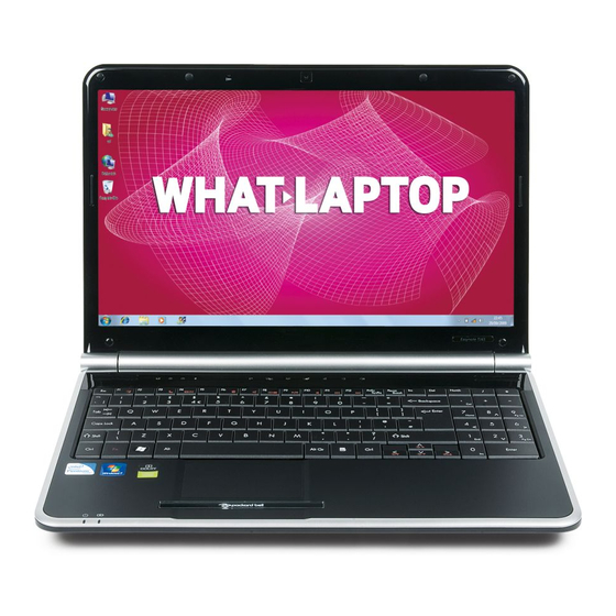
Packard Bell EasyNote LJ65 Laptop Manuals
Manuals and User Guides for Packard Bell EasyNote LJ65 Laptop. We have
1
Packard Bell EasyNote LJ65 Laptop manual available for free PDF download: Service Manual
Packard Bell EasyNote LJ65 Service Manual (220 pages)
Brand:
Packard Bell
| Category:
Laptop
| Size: 7.71 MB
Table of Contents
Revision History
2
Table of Contents
7
System Specifications
11
Features
11
Storage Subsystem
12
Optical Drive
12
Dimensions and Weight
12
Privacy Control
12
Power Subsystem
13
Special Keys and Controls
13
System Block Diagram
14
Your Notebook Tour
15
Front View
15
Left View
16
Right View
17
Rear View
17
Bottom View
18
Keyboard Area (Selected Models)
19
LCD Panel
20
Status Indicators
21
Touchpad Basics
22
Using the Keyboard
23
Key Types
23
Windows Keys
24
System Keys
25
Using the System Utilities
26
Acer Gridvista (Dual-Display Compatible)
26
Hardware Specifications and Configurations
27
System Utilities
37
BIOS Setup Utility
37
Navigating the BIOS Utility
37
Information
38
Main
39
Advanced
40
Security
42
Setting a Password
43
Removing a Password
43
Changing a Password
44
Power
45
Boot
47
Exit
48
BIOS Flash Utilities
49
DOS Flash Utility
50
Winflash Utility
52
Remove HDD/BIOS Password Utilities
53
Using Boot Sequence Selector
55
Using Dmitools
56
Using the Lan Mac Eeprom Utility
57
Machine Disassembly and Replacement
59
Disassembly Requirements
59
General Information
60
Pre-Disassembly Instructions
60
Disassembly Process
60
External Module Disassembly Process
61
External Modules Disassembly Flowchart
61
Removing the Battery Pack
62
Removing the SD Dummy Card
63
Removing the Lower Covers
64
Removing the Optical Drive Module
65
Removing the DIMM Modules
67
Removing the WLAN Module
68
Removing the Primary HDD Module
70
Removing the Secondary HDD Module
72
Main Unit Disassembly Process
74
Main Unit Disassembly Flowchart
74
Removing the Switch Cover
75
Removing the Media Board
78
Removing the Keyboard
79
Removing the LCD Module
81
Removing the Upper Cover
86
Removing the Touchpad Bracket
90
Removing the Media Board FFC
91
Removing the LED Board
92
Removing the Speaker Module
93
Removing the RTC Battery
95
Removing the Modem Board
96
Removing the USB Board
98
Removing the Mainboard
100
Removing the RJ-11 Jack
101
Removing the CPU Fan
103
Removing the Thermal Module
104
Removing the CPU
105
LCD Module Disassembly Process
106
LCD Module Disassembly Flowchart
106
Removing the LCD Bezel
107
Removing the Camera Module
108
Removing the LCD Panel
109
Removing the Power Board
110
Removing the LCD Brackets and FPC Cable
111
Removing the Microphone Module
113
Removing the Antennas
114
LCD Module Reassembly Procedure
116
Replacing the Antennas, Power Board, and MIC
116
Replacing the LCD Panel
119
Replacing the Camera Module
121
Replacing the LCD Bezel
122
Main Module Reassembly Procedure
124
Replacing the CPU
124
Replacing the Thermal Module
124
Replacing the CPU Fan
125
Replacing the RJ-11 Jack
126
Replacing the Mainboard
127
Replacing the USB Board
128
Replacing the Modem Board
129
Replacing the Speaker Module
130
Replacing the LED Board
131
Replacing the Media Board FFC
131
Replacing the Touchpad Bracket
132
Replacing the Upper Cover
132
Replacing the LCD Module
136
Replacing the Keyboard
139
Replacing the Media Board
140
Replacing the Switch Cover
141
Replacing the Hard Disk Drive Modules
143
Replacing the WLAN Module
144
Replacing the DIMM Modules
144
Replacing the ODD Module
145
Replacing the Lower Covers
145
Replacing the SD Dummy Card
147
Replacing the Battery
147
Troubleshooting
149
Common Problems
149
Power on Issue
150
No Display Issue
151
Random Loss of BIOS Settings
152
LCD Failure
153
Built-In Keyboard Failure
153
Touchpad Failure
154
Internal Speaker Failure
155
Internal Microphone Failure
157
HDD Not Operating Correctly
158
ODD Failure
159
USB (Right Side) Failure
163
Wireless Function Failure
164
Bluetooth Function Test Failure
165
Easy Button Failure
166
Thermal Unit Failure
167
External Mouse Failure
167
Other Failures
168
Motherboard CMOS Discharge
169
Intermittent Problems
169
Undetermined Problems
169
Post Codes
171
Chipset POST Codes
171
Sec
171
Memory
171
BDS & Specific Action
172
Each PEIM Entry Point Used in 80_PORT
174
Each Driver Entry Point Used in 80_PORT
174
Each Smmdriver Entry Point Used in 80_PORT
177
Jumper and Connector Locations
179
Top View
179
Bottom View
180
LS-5022P USB Board
181
LS-5024P Cap Sensor Board
181
LS-5026P LED Board
181
LS-5027P SW Board
182
Clearing Password Check and BIOS Recovery
183
Clearing Password Check
183
BIOS Recovery by Crisis Disk
184
FRU (Field Replaceable Unit) List
185
Packard Bell Easynote LJ65 Exploded Diagrams
186
Main Assembly
186
Rear Assembly
187
LCD Assembly
188
Base Top Assembly
189
Packard Bell Easynote LJ65 FRU List
190
Screw List
198
Model Definition and Configuration
200
Packard Bell Easynote LJ65 Series
200
Test Compatible Components
209
Microsoft Windows
210
Online Support Information
215
Index
217
Advertisement
Advertisement
Related Products
Packard Bell EasyNote LJ75
Packard Bell EasyNote LJ61
Packard Bell EasyNote LJ77
Packard Bell Easynote LE69KB
Packard Bell EasyNote LX8
Packard Bell EasyNote LS11HR
Packard Bell EasyNote LS13HR
Packard Bell EasyNote DT85
Packard Bell EasyNote C3
Packard Bell EasyNote B3
Packard Bell Categories
Laptop
Monitor
Desktop
DVD Player
GPS
More Packard Bell Manuals
Login
Sign In
OR
Sign in with Facebook
Sign in with Google
Upload manual
Upload from disk
Upload from URL