Sign In
Upload
Manuals
Brands
MTS Systems Manuals
Test Equipment
Landmark 370 Series
MTS Systems Landmark 370 Series Test Manuals
Manuals and User Guides for MTS Systems Landmark 370 Series Test. We have
2
MTS Systems Landmark 370 Series Test manuals available for free PDF download: Product Information, Operation
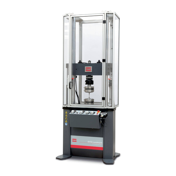
MTS Systems Landmark 370 Series Product Information (136 pages)
Tabletop Load Units
Brand:
MTS Systems
| Category:
Test Equipment
| Size: 6.86 MB
Table of Contents
Table of Contents
3
Technical Support
9
How to Get Technical Support
9
Start with Your Manuals
9
Technical Support Methods
9
Outside the U
9
Before You Contact MTS
9
Know Your Site Number and System Number
9
Know Information from Prior Technical Assistance
10
Identify the Problem
10
Know Relevant Computer Information
10
Know Relevant Software Information
10
If You Contact MTS by Phone
11
Identify System Type
11
Be Prepared to Troubleshoot
11
Write down Relevant Information
11
After You Call
12
Problem Submittal Form
12
Preface
13
Before You Begin
13
Safety First
13
Other MTS Manuals
13
Documentation Conventions
13
Hazard Conventions
13
Other Special Text Conventions
14
Special Terms
14
Illustrations
14
Electronic Manual Conventions
14
Hypertext Links
14
Safety
15
General Safety Practices
16
Safety Practices before Operating the System
17
Read All Manuals
17
Locate Lockout/Tagout Points
17
Know Facility Safe Procedures
17
Locate Emergency Stop Buttons
17
Know Controls
17
Have First Aid Available
17
Know Potential Crush and Pinch Points
17
Be Aware of Component Movement with Hydraulics off
18
Know Electrical Hazards
18
Ensure Correct Cable Connection
18
Keep Bystanders Safely Away
18
Wear Proper Clothing
18
Remove Flammable Fluids
18
Know Compressed Gas Hazards
19
Check Bolt Ratings and Torques
19
Practice Good Housekeeping
20
Protect Hoses and Cables
20
Provide Proper Hydraulic Fluid Filtration
20
Protect Accumulators from Moving Objects
20
Record Changes
20
Provide Test Area Guards
20
Do Not Exceed the Maximum Supply Pressure
20
Do Not Disable Safety Devices
21
Use Appropriately Sized Fuses
21
Provide Adequate Lighting
21
Provide Adequate Ventilation
21
Provide Means to Access Out-Of-Reach Components
21
Safety Practices While Operating the System
22
Wear Appropriate Personal Protection
22
Provide Test Area Enclosures
22
Specimen Temperature Changes
22
Handle Chemicals Safely
22
Know Servohydraulic System Interlocks
22
Know System Limits
23
Do Not Disturb Sensors
23
Ensure Secure Cables
23
Stay Alert
23
Contain Small Leaks
23
Stay Clear of Moving Equipment/Avoid Crush Points
23
Know the Causes of Unexpected Actuator Motions
23
Do Not Use RF Transmitters
24
Load Unit Hazard Labels
24
Hazard Labels North America (Part Number 100-164-553)
24
Hazard Labels Rest of World (Part Number 100-164-565)
25
Hazard Label for HSM Needle Valve Adjustment
26
Hazard Label for HSM Needle Valve Adjustment
27
Introduction
29
Overview
30
What You Need to Know
32
Related Products
33
EU Declarations
33
EC Declaration of Conformity (Machinery Directive 2006/42/EC Annex II 1A)
33
Declaration of Incorporation (Machinery Directive 2006/42/EC Annex II 1B)
33
Component Description
35
Functional Description
40
Load Frame
40
Crosshead
40
Manifold
40
Pressure Control
41
Transducers
41
Series 661 Force Transducers
42
Dimensions
43
Series 662 Force Transducers
44
Dimensions
45
Specifications
45
Installation
47
About Installation
48
Lifting and Moving the Load Unit
48
Overview
48
Lift and Move the Load Unit
49
Connecting Cables
56
Prerequisite
56
Cable Connections
56
Low Flow Power Supply
57
Connect Hydraulics
59
Unlock the Crosshead
59
Operation
63
Control Module
64
Specimen Installation
65
Prerequisites
65
Install the Specimen
66
Position the Crosshead Manually
68
Manually Clamp the Crosshead
70
Crosshead Clamping Bolt Torque Values
71
Move the Crosshead Hydraulically
71
Adjust the Grip Clamp Rate
72
Adjust the Grip Clamp Force
73
Handset Control
73
Handset Control Functions
73
Standard Test Area Enclosure Operation
75
Hydraulic Power off
75
Specimen Installation and Setup
75
Run Mode
76
Service
76
Emergency Stop and Actuator Velocity Limiting Switch
77
Interlock Logic
78
Test Area Enclosure with Light Curtain
79
Additional Station Manager and Interlock Functionality (Units Equipped with Electromagnetic Rotary Servo Motor Only)
81
Maintenance
83
Routine Maintenance Overview Checklist
85
Other Maintenance Tasks
90
Daily Inspections
91
Clean the Columns
91
Prevent Rust
92
Recommended Supplies
92
Maintain Airmount Pressures
95
Label Inspection
97
Adjust the Hydraulic Locks
97
Lubricate the Crosshead Locking Bolts
101
Aligning the Force Transducer
102
Required Equipment
102
Align the Force Transducer
103
Series 111 Accumulator: Maintenance Overview
106
Series 111 Accumulator: Check and Change Precharge Pressure
109
Equipment
109
Prerequisites
109
Check the Precharge Pressure
110
Change the Precharge Pressure
111
Decrease Pressure
112
Increase Pressure
112
Actuator
113
Weekly
113
Monthly
113
Yearly
113
Change the HSM Filter
114
Change the HSM Filter
115
252 Servovalve
115
Replacing the Servovalve Filter Element
115
Replace the Servovalve Filter Element
116
Adjusting the Mechanical Null
118
Adjust the Mechanical Null
118
Performing Sensor Calibration
122
Decommissioning
123
Decommissioning Decommission the System
123
Declarations
127
Declaration of Conformity
128
Original - Page 1 of 3 - Doc Load Unit - December 21, 2009
128
Original - Page 2 of 3 - Doc Load Unit - December 21, 2009
129
Original - Page 3 of 3 - Doc Load Unit - December 21, 2009
130
Declaration of Incorporation
131
Original - Page 1 of 3 - Doi Load Unit - December 21, 2009
131
Original - Page 2 of 3 - Doi Load Unit - December 21, 2009
132
Original - Page 3 of 3 - Doi Load Unit - December 21, 2009
133
Advertisement
MTS Systems Landmark 370 Series Operation (134 pages)
Test System
Brand:
MTS Systems
| Category:
Test Equipment
| Size: 10.94 MB
Table of Contents
Table of Contents
3
Technical Support
7
How to Get Technical Support
7
Start with Your Manuals
7
Technical Support Methods
7
Outside the U
7
Before You Contact MTS
7
Know Your Site Number and System Number
7
Know Information from Prior Technical Assistance
8
Identify the Problem
8
Know Relevant Computer Information
8
Know Relevant Software Information
8
If You Contact MTS by Phone
9
Identify System Type
9
Be Prepared to Troubleshoot
9
Write down Relevant Information
9
After You Call
10
Problem Submittal Form
10
Preface
11
Before You Begin
11
Safety First
11
Documentation Conventions
11
Hazard Conventions
11
Other Special Text Conventions
12
Special Terms
12
Illustrations
12
Electronic Manual Conventions
12
Hypertext Links
12
Safety
13
General Safety Practices
14
Safety Practices before Operating the System
14
Safety Practices While Operating the System
19
Load Unit Hazard Labels
21
System Introduction
25
About this Manual
26
About Other MTS Documentation
26
Hardware Manuals
26
Software Help
26
Documentation Access on Mts.com
26
System Overview
27
Load Frame Overview
28
Introduction
28
Component Identification
28
Load Frame Controls Overview
29
Control Panel
29
Software Overview
31
MTS Flextest (Series 793) Controller Software - Station Manager Application
31
MTS Testsuite Test Software - MTS Multipurpose (MP) Express Application
36
Key Concepts
41
About this Chapter
42
Understanding Your MTS Software
42
MTS Flextest Controller Software and the Station Manager Application
42
MTS Testsuite Test Software and the MTS TW Express Application
43
Understanding MTS File Types
44
File Types
44
Creating and Modifying Parameter Sets
46
Selecting and Saving Parameter Sets
47
How MTS Files Work Together
47
Understanding the Control Loop
48
Closed Loop Control Step-By-Step
48
Understanding Control Channels and Control Modes
50
Control Channel (for Example, Actuator)
50
Control Modes (for Example, Force or Displacement)
50
Using Control Modes
50
Control Mode Example
50
Using Detectors and Actions to Protect Yourself and Your Equipment
50
Sensor Limits
51
Detector Actions
51
Setting Limits before Specimen Installation
51
Setting Limits before Testing
51
Using the E-Stop Control
51
Understanding the Load Train
51
Positioning the Crosshead to Install the Specimen
52
Positioning the Actuator to Install the Specimen
53
Optimizing System Response before Testing
53
Why Tuning Is Beneficial
53
Loop Tuning for the Example Test
53
Understanding and Resolving Error Conditions
53
Using Application Logs to Identify Error Conditions
54
Running the Example HCF Test
55
About this Chapter
56
Adapting this Chapter to Your System
56
Test Procedure Overview
56
Prepare for Specimen Installation
57
Turn on the Station
58
Open the Station Manager Application
58
Verify Calibration Files
60
Set up Meters for Specimen Installation
61
Set Limits for Specimen Installation
64
Zero the Force Signal
66
Set Initial Tuning Parameters
67
Install the Specimen
70
Power up the Pump and HPU
70
Position the Actuator Using Displacement Control
71
Zero Displacement
73
Clamp the Specimen in the Lower Grip
74
Position the Crosshead
76
Move the Specimen into the Upper Grip Using Displacement Control
76
Switch to Force Control
77
Clamp the Specimen in the Upper Grip
77
Check and Reset Meter History
78
Prepare to Run the Test
79
Perform Basic Performance Tuning
79
Switch to Peak Valley Meters
88
Adjust Limits for the Test
90
Show Station Manager Scope and Meters for the Test
91
Minimize Station Manager
92
Run the Example HCF Test
93
Open the MPX Application
94
Select the Test
94
If Necessary, Correct any Resource Errors
95
Create a New Test Run
95
Run the Test
97
Review the Results
98
Generate a Report
99
Save the Test and Minimize MPX
100
Remove the Specimen
100
Remove Displacement Limits
101
Switch to Running Max/Min Displacement and Force Meters
101
If Appropriate, Remove the Intact Specimen
102
If Appropriate, Remove the Broken Specimen
105
Recover from a Tripped Limit
106
If Necessary, Recover from a Tripped Force Limit
107
If Necessary, Recover from a Tripped Displacement Limit
110
Maintenance
115
Routine Maintenance Overview Checklist
116
Maintenance Intervals
119
Daily Inspections
120
Decommissioning
123
Decommission
124
Index
127
Advertisement
Related Products
MTS Systems 318 Series
MTS Systems 318.10
MTS Systems 318.25
MTS Systems 318.50
MTS Systems 311 Series
MTS Systems 311.21
MTS Systems 311.31
MTS Systems 311.51
MTS Systems 311.61
MTS Systems 311.71
MTS Systems Categories
Accessories
Test Equipment
Industrial Equipment
Cell Phone
Amplifier
More MTS Systems Manuals
Login
Sign In
OR
Sign in with Facebook
Sign in with Google
Upload manual
Upload from disk
Upload from URL