
Related Manuals for MTS Systems Landmark 370 Series


Summary of Contents for MTS Systems Landmark 370 Series
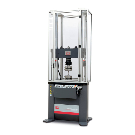
- Page 1 MTS Landmark™ Tabletop Load Units Product Information Landmark™ Axial Load Unit, Landmark™ 100 Hz Elastomer, Bionix® Axial/Torsional 100-206-897 F...
- Page 2 Aero ST, Aero-90, AeroPro, Criterion, cRPC, Exceed, First Road, Landmark, MAST, MicroProfiler, MPT, MTS Exceed, MTS Fundamentals, MTS TestSuite, ReNew, SilentFlo, TempoGuard, TestLine, Tytron, Virtual Test Lab, and VTL are trademarks of MTS Systems Corporation within the United States. These trademarks may be registered in other countries.
-
Page 3: Table Of Contents
Contents Technical Support How to Get Technical Support Start with your manuals Technical support methods Outside the U.S. Before You Contact MTS Know your site number and system number Know information from prior technical assistance Identify the problem Know relevant computer information Know relevant software information If You Contact MTS by Phone Identify system type... - Page 4 Contents Be aware of component movement with hydraulics off Know electrical hazards Ensure correct cable connection Keep bystanders safely away Wear proper clothing Remove flammable fluids Know compressed gas hazards Check bolt ratings and torques Practice good housekeeping Protect hoses and cables Provide proper hydraulic fluid filtration Protect accumulators from moving objects Record changes...
- Page 5 Contents What you need to know Related products EU Declarations EC Declaration of Conformity (Machinery Directive 2006/42/EC Annex II 1A) Declaration of Incorporation (Machinery Directive 2006/42/EC Annex II 1B) Component Description Functional Description Load frame Crosshead Manifold Pressure control Transducers Series 661 Force Transducers Dimensions Series 662 Force Transducers...
- Page 6 Contents Crosshead Clamping Bolt Torque Values Move the Crosshead Hydraulically Adjust the Grip Clamp Rate Adjust the Grip Clamp Force Handset Control Handset Control Functions Standard Test Area Enclosure Operation Hydraulic Power Off Specimen Installation and Setup Run Mode Service Emergency Stop and Actuator Velocity Limiting Switch Interlock logic Test Area Enclosure with Light Curtain...
- Page 7 Contents Check the Precharge Pressure Change the Precharge Pressure Decrease Pressure Increase Pressure Actuator Weekly Monthly Yearly Change the HSM Filter Change the HSM Filter 252 Servovalve Replacing the Servovalve Filter Element Replace the Servovalve Filter Element Adjusting the Mechanical Null Adjust the Mechanical Null Performing Sensor Calibration Decommissioning...
-
Page 9: Technical Support
Technical Support Technical Support How to Get Technical Support Start with your manuals The manuals supplied by MTS provide most of the information you need to use and maintain your equipment. If your equipment includes software, look for online help and README files that contain additional product information. -
Page 10: Know Information From Prior Technical Assistance
Technical Support When you have more than one MTS system, the system job number identifies your system. You can find your job number in your order paperwork. Example system number: US1.42460 Know information from prior technical assistance If you have contacted MTS about this problem before, we can recall your file based on the: MTS case number Name of the person who helped you Identify the problem... -
Page 11: If You Contact Mts By Phone
Technical Support If You Contact MTS by Phone A Call Center agent registers your call before connecting you with a technical support specialist. The agent asks you for your: Site number Email address Name Company name Company address Phone number where you can be reached If your issue has a case number, please provide that number. -
Page 12: After You Call
Technical Support After you call MTS logs and tracks all calls to ensure that you receive assistance for your problem or request. If you have questions about the status of your problem or have additional information to report, please contact Technical Support again and provide your original case number. Problem Submittal Form Use the Problem Submittal Form to communicate problems with your software, hardware, manuals, or service that are not resolved to your satisfaction through the technical support process. -
Page 13: Preface
Preface Preface Before You Begin Safety first! Before you use your MTS product or system, read and understand the safety information provided with your system. Improper installation, operation, or maintenance can result in hazardous conditions that can cause severe personal injury or death, or damage to your equipment and specimen. Again, read and understand the safety information provided with your system before you continue. -
Page 14: Other Special Text Conventions
Preface Other special text conventions Important: Important notices provide information about your system that is essential to its proper function. While not safety-related, if the important information is ignored, test results may not be reliable, or your system may not operate properly. Note: Notes provide additional information about operating your system or highlight easily overlooked information. -
Page 15: Safety
Safety Safety General Safety Practices Safety Practices Before Operating the System Safety Practices While Operating the System Load Unit Hazard Labels MTS Landmark™ Tabletop Load Units - Product Information... -
Page 16: General Safety Practices
Safety General Safety Practices If you have system related responsibilities (that is, if you are an operator, service engineer, or maintenance person), you should study this manual carefully before you attempt to perform any test system procedure. You should receive training on this system or a similar system to ensure a thorough knowledge of your equipment and the safety issues that are associated with its use. -
Page 17: Safety Practices Before Operating The System
Safety Safety Practices Before Operating the System Before you apply power to the test system, review and complete all of the safety practices that are applicable to your system. The goal, by doing this, is to improve the safety awareness of all personnel involved with the system and to maintain, through visual inspections, the integrity of specific system components. -
Page 18: Be Aware Of Component Movement With Hydraulics Off
Safety An important consideration for servohydraulic systems is that when power is interrupted, it is likely that stored accumulator pressure will persist for some time within the system. In addition, it is likely that as stored energy dissipates, gravity will cause portions of the system to move. Be aware of component movement with hydraulics off For hydraulic systems, be aware that mechanical assemblies can shift or drift due to changes within hydraulic hardware when hydraulics are turned off. -
Page 19: Know Compressed Gas Hazards
Safety Know compressed gas hazards Your system may contain accumulators that require a high-pressure gas precharge (pressures that exceed 138 bar [2000 psi]). High-pressure devices are potentially dangerous because a great amount of energy is available in the event of an uncontrolled expansion or rupture. Observe the following safety practices when you work with high-pressure air or gases: When you charge an accumulator, follow all the charging instructions provided in the appropriate product information manuals. -
Page 20: Practice Good Housekeeping
Safety On rare occasions, a fastener can fail even when it is correctly installed. Failure usually occurs during torquing, but it can occur several days later. Failure of a fastener can result in a high velocity projectile. Therefore, it is a good practice to avoid stationing personnel in line with or below assemblies that contain large or long fasteners. -
Page 21: Do Not Disable Safety Devices
Safety Do not disable safety devices Your system may have active or passive safety devices installed to prevent system operation if the device indicates an unsafe condition. Do not disable such devices as it may result in unexpected system motion. Use appropriately sized fuses Whenever you replace fuses for the system or supply, ensure that you use a fuse that is appropriately sized and correctly installed. -
Page 22: Safety Practices While Operating The System
Safety Safety Practices While Operating the System Wear appropriate personal protection Wear eye protection when you work with high-pressure hydraulic fluid, high-pressure air pressure, breakable specimens, or when anything characteristic to the specimen could break apart. Wear ear protection when you work near electric motors, pumps, or other devices that generate high noise levels. -
Page 23: Know System Limits
Safety Know system limits Never rely on system limits such as mechanical limits or software limits to protect you or any personnel. System limits are designed to minimize the chance of accidental damage to test specimens or to equipment. Test all limits for proper operation immediately before a test. Always use these limits and adjust them properly. -
Page 24: Do Not Use Rf Transmitters
Safety and hoses; shorted wires; overstressed feedback devices; and damaged components within the servocontrol loop). Eliminate any condition that could cause unexpected actuator motion. Do not use RF transmitters Keep radio frequency (RF) transmitters away from the workstation computers, remote terminals, and electronics consoles. -
Page 25: Hazard Labels Rest Of World (Part Number 100-164-565)
Safety Hazard Labels Rest of World (part number 100-164-565) Icon Description Failure to follow operating instructions can cause death or serious injury. Read and understand the operator’s manual before using this machine. Moving parts can crush and cut. Keep hands clear while operating machine. Pushing or striking load frame may cause it to tip over. -
Page 26: Hazard Label For Hsm Needle Valve Adjustment
Safety Icon Description Flying debris and loud noise hazard. Wear ear and eye protection. Hydraulic pressure beyond rated working pressure can rupture components, cause severe personal injury, and damage equipment. Do not exceed 21 MPa (3000 psi) rated working pressure. Hazard Label for HSM Needle Valve Adjustment Icon Description... -
Page 27: Hazard Label For Hsm Needle Valve Adjustment
Safety Hazard Label for HSM Needle Valve Adjustment Icon Description The HSM needle valve is factory adjusted and should not be adjusted in the field except by MTS Field Service Engineers. MTS Landmark™ Tabletop Load Units - Product Information... -
Page 29: Introduction
Introduction Introduction Overview What you need to know Related products EU Declarations EC Declaration of Conformity (Machinery Directive 2006/42/EC Annex II 1A) Declaration of Incorporation (Machinery Directive 2006/42/EC Annex II 1B) Component Description Functional Description Load frame Crosshead Manifold Pressure control Transducers Series 661 Force Transducers Dimensions... -
Page 30: Overview
Introduction Overview This manual documents Series 370 Tabletop Load Units. These small load units are available in the following configurations: 370 Axial Load Frame The axial load unit has an actuator that applies linear forces to specimens. The 100 Hz elastomer load unit is configured specifically for characterizing the dynamic properties of elastomeric materials and components. - Page 31 Introduction 370 Axial-Torsional Load Frame with Hydraulic Rotary Actuator The axial-torsional load unit with hydraulic rotary actuator, combines an axial actuator with a torsional actuator to simultaneously apply axial and torsional forces to specimens. MTS Landmark™ Tabletop Load Units - Product Information...
-
Page 32: What You Need To Know
What you need to know MTS Systems Corporation assumes that you know how to use your controller. For information about performing any controller-related step in this manual's procedure, see the appropriate manual. You are expected to know how to perform the following procedures: Turn hydraulic pressure on and off. -
Page 33: Related Products
Introduction Zero a sensor output. Use your grips and fixtures. Define a simple test. Run a test. Related products The Series 370 Tabletop Load Unit includes several other products. For product-specific information and maintenance procedures, see the following product information manuals. The Series 111 Accumulator Product Information manual (MTS part number 011-553-304) The Series 252 Servovalve Product Information manual (MTS part number 011-182-906) - Page 34 Introduction machinery sub-systems (load unit, controller, and optional equipment such as hydraulic service manifolds, hydraulic power unit, grips, fixtures, extensometers, furnaces, ovens and environmental chambers, and so forth) conforms to the requirements of Machinery Directive 2006/42/EC and other applicable EC Directives. This will require the customer to affix the CE Marking on the system assembly and to complete the EC Declaration of Conformity before putting the machinery into service.
-
Page 35: Component Description
Introduction Component Description Rear View of an Axial-Torsional Load Frame with Hydraulic Rotary Actuator MTS Landmark™ Tabletop Load Units - Product Information... - Page 36 Introduction Component Descriptions Item Component Description Encoder Measures the angle of the rotary actuator’s travel. The encoder is coupled to the rotary actuator. Rotary actuator Applies rotational forces to a specimen. The rotary actuator is coupled to the linear actuator for axial-torsional load units. LVDT Measures the displacement of the linear actuator’s travel.
- Page 37 Introduction Item Component Description Servovalves Control both the amount and the direction of fluid entering the actuator using a high response valve. They determine how fast the actuator can move. A servovalve is required for each actuator. Linear actuator Applies axial forces to specimens. The actuator is a hydraulically powered device that provides linear displacement of (or forces into) a specimen.
- Page 38 Introduction Rear View of Axial-Torsional Load Frame with Electromagnetic Rotary Servo Motor Component Descriptions Item Component Description LVDT Measures the displacement of the linear actuator’s travel. The linear variable displacement transducer (LVDT) is located inside the actuator. Encoder Connector The encoder measures the angle of the rotary actuator’s travel.
- Page 39 Introduction Item Component Description Crosshead Moves up and down the column to accommodate different sized specimens and fixtures. The crosshead is stiff and light weight; it is one end of the force train. Crosshead lifts Raise and lower the crosshead hydraulically to accommodate different specimen sizes.
-
Page 40: Functional Description
Introduction Functional Description The load unit is a stand-alone testing structure. It consists of the following components: Load frame Crosshead lifts Manifold Actuators Servovalves Accumulators Two or more transducers Load frame The load frame is the basic structure. Two columns allow a crosshead to be moved up or down to accommodate different size specimens and fixtures. -
Page 41: Pressure Control
Introduction a pressure-line accumulator to provide fluid storage so that a constant line pressure can be maintained at the servovalves for maximum performance. The return-line accumulator minimizes return-line pressure fluctuations. Pressure control The load unit can be configured for several pressure configurations: The free flow configuration passes the hydraulic pressure from the HPU (or hydraulic service manifold) through the manifold to the hydraulic components. -
Page 42: Series 661 Force Transducers
Introduction Series 661 Force Transducers The force transducer commonly used with the axial tabletop Series 370 Load Unit is a Series 661 Force Transducer. There is no manual for the force transducer. The following table provides the specifications for the force transducers. Parameter Specification Capacity... -
Page 43: Dimensions
Introduction Dimensions The following dimensions are rounded off to the nearest millimeter. Series 661 Force Transducer Dimensions Item Dimensions 104.6 mm (4.12 in) 31.8 mm (1.25 in) 0.8 mm (0.03 in) 66.5 mm (2.62 in) 32.0 mm (1.3 in) 6.4 mm (0.25 in) 5.1 mm (0.20 in) Depth Near Side: 25.4 mm (1.00 in) -
Page 44: Series 662 Force Transducers
Introduction Series 662 Force Transducers The force transducer commonly used with the axial-torsional tabletop Series 370 Load Unit is a Series 662 Force Transducer. There is no manual for the force transducer. The following table provides the specifications for the force transducers. Parameter Specification Capacity... -
Page 45: Dimensions
Introduction Dimensions The following dimensions are rounded off to the nearest millimeter. Series 662 Force Transducer Dimensions Dimensions Dimensions Item Model 662.20H-04 Model 662.20H-05 111.3 mm (4.38 in) 158.8mm (6.25 in) B (both ends) 101.6 mm (4.00 in) 146.0 mm (5.75 in) C [bolt circle diameter (both ends)] 78.7 mm (3.10 in) 120.7 mm (4.75 in) 127.0 mm (5.00 in) -
Page 47: Installation
Installation Installation About Installation Lifting and Moving the Load Unit Overview Lift and Move the Load Unit Connecting Cables Prerequisite Cable connections Low Flow Power Supply Connect Hydraulics Unlock the Crosshead MTS Landmark™ Tabletop Load Units - Product Information... -
Page 48: About Installation
Installation About Installation This section provides information on load unit installation. After installation is complete, it is recommended that you verify operation before putting the load unit into service and start running tests. Lifting and Moving the Load Unit This section describes how to lift and move the Series 370 Load Unit. Overview You will need a fork lift or overhead crane capable of lifting the load unit. -
Page 49: Lift And Move The Load Unit
Installation Approximate Weights of Load Units Model Base Mount Crosshead Mount Approximate Weight Approximate Weight 370.10 631 kg (1390 lb) 815 kg (1795 lb) 370.25 871 kg (1920 lb) 1091 kg (2405 lb) 370.50 1563 kg (3445 lb) 1756 kg (3870 lb) Lift and Move the Load Unit 1. - Page 50 Installation Lock the Crosshead Item Description 190 N · m (140 lbf · ft) Lock the Crosshead Item Description Hydraulically Locked Crossheads Manually Locked Crossheads Manual locks not available on Models 370.25 and 370.50. 4. Before you move the load unit, check the following: The floor where the load unit will sit can bear its weight.
- Page 51 Installation 5. Move the load unit slowly to its installation site. Move the load unit only with slings or chains using an overhead lifting device. Lift the load unit only as high as necessary. Lift Point Locations Item Description M20 X 2.50 mm Holes for Swivel Hoist Rings (supplied for lifting) Slings Warning: Airmounts can be overinflated and then explode.
- Page 52 Installation accurate pressure gage. Each airmount's inflated height—measured from the floor to the bottom of the load unit’s leg—should be 57–63 mm (2.25–2.5 in). The load unit can be moved on its pallet with a fork lift, or with its lifting hoist rings (actuator integral to the base), or with slings (actuator integral to the crosshead) using an overhead lifting device.
- Page 53 Installation Warning: Airmounts can be overinflated and then explode. You can be seriously hurt if an airmount explodes, sending fragments flying. Only inflate airmounts that have the full weight of the load unit resting on them. Never inflate an airmount above 0.55 MPa (80 psi). Check airmount pressures with an accurate pressure gage.
- Page 54 Installation Isolation Pad or Airmount Adjustment Item Description Airmount Foot Support Isolation Pads Load Unit 57 - 63 mm (2.25–2.5 in) 83 - 89 mm (3.25–3.5 in) 0.41 MPa (60 psi) 0.55 MPa (80 psi) Install shims to level. 7. Remove the slings/chains. 8.
- Page 55 Threaded Stud Spring Self Locking Nut 9. Contact MTS Systems Corporation to arrange for installation services. In the U.S. and Canada, call the MTS Call Center at 1-800-328-2255. Elsewhere, contact your local MTS office. MTS Landmark™ Tabletop Load Units - Product Information...
-
Page 56: Connecting Cables
Installation Connecting Cables Your controller manual should have cabling information about the connections described in this section. Most controller manuals provide the signal pinouts of the connector, assembly numbers for standard MTS cables, and cable specifications for cables you may build. Prerequisite You must have either a cable assembly drawing of your test system, or you must know the system controller well enough to determine each type of cable connection. -
Page 57: Low Flow Power Supply
Installation Low Flow Power Supply Connect the low flow power supply as shown in the following figure. If the load frame is equipped with a test area enclosure, the door interlock jumper would be replaced with the cable from the test area enclosure. - Page 58 Installation Connect the Low Flow Power Supply Item Description Main Power In To Low Flow Solenoid To Load Frame Rear Panel Door Interlock Jumper (units without an enclosure) Cable from Test Area Enclosure (units with an enclosure) Cable from Drive Enclosure (units with an electromagnetic rotary servomotor) MTS Landmark™...
-
Page 59: Connect Hydraulics
Installation Connect Hydraulics This procedure describes how to connect the load unit to the hydraulic power source. The load unit may be connected directly to the hydraulic power unit (also called HPU), to hydraulic plumbing in the workplace, or through a hydraulic service manifold. Caution: Hydraulic fluid must be properly filtered. - Page 60 Installation Caution: The crosshead can slowly drift down the columns if the locks are turned off and when hydraulic pressure is turned off. The crosshead can damage any test fixtures, grips, and specimen in its path. Unlock the crosshead only to reposition it. Always lock the crosshead after you have repositioned it and never leave the crosshead unlocked.
- Page 61 Installation Loosen the Manual Crosshead Locking Bolts Item Description 136 N·m (100 lbf·ft) 271 N·m (200 lbf·ft) 271 N·m (200 lbf·ft) Loosen the Manual Crosshead Locking Bolts Item Description 190 N·m (140 lbf·ft) 3. Cycle the lock control to unclamp, and then reclamp, the crosshead. 4.
-
Page 63: Operation
Operation Operation Control Module Specimen Installation Prerequisites Install the Specimen Position the Crosshead Manually Manually Clamp the Crosshead Crosshead Clamping Bolt Torque Values Move the Crosshead Hydraulically Adjust the Grip Clamp Rate Adjust the Grip Clamp Force Handset Control Handset Control Functions Standard Test Area Enclosure Operation Hydraulic Power Off Specimen Installation and Setup... -
Page 64: Control Module
Operation Control Module The controls for the Series 370 Load Unit are located on a module mounted to the front of the load unit. The followingcontrol panel is shown with all available options. The control panel on your load unit might not have all of these controls depending on the specific configuration. -
Page 65: Specimen Installation
Operation Item Control Description Emergency Stop Removes the hydraulic power and stops the test program. Press this button to remove hydraulic power, and twist the switch clockwise to release it. Use the Emergency Stop button to shut down your test if something unexpected should happen. Actuator Velocity Controls actuator velocity. -
Page 66: Install The Specimen
Operation Warning: The crosshead is very heavy. A dropping crosshead can crush hands, damage grips, and smash specimens. Be careful when working in a crush zone. To reduce the hazards in this procedure, observe the following: Set and enable displacement interlocks to limit the actuator’s movement. Ensure that the crosshead is locked. - Page 67 Operation position of the actuator, and the size of the fixtures or grips being used. 3. Install the specimen. Specimen installation varies according to the type of grip being used. For installation instructions, see the appropriate grip manual. MTS manufactures a variety of grips: The Series 641 Hydraulic Wedge Grips (hydraulically controlled) are specifically designed for static or fatigue testing applications.
-
Page 68: Position The Crosshead Manually
Operation Position the Crosshead Manually This procedure describes how to position a crosshead for a load unit with no hydraulic crosshead lifts or locks. Warning: The crosshead is very heavy. A dropping crosshead can crush hands, damage grips, and smash specimens. Observe the following precautions to reduce the possibility of unexpected crosshead movement: Ensure that the crosshead is locked. - Page 69 Operation 5. Loosen the crosshead locking bolts in 1/4 turn steps (counterclockwise). The following figure shows the sequence of loosening the crosshead bolts. Crosshead Locking Bolt Torque Item Description 190 N·m (140 lbf·ft) Crosshead Locking Bolt Torque Item Description 190 N·m (140 lbf·ft) 271 N·m (200 lbf·ft) 6.
-
Page 70: Manually Clamp The Crosshead
Operation Manually Clamp the Crosshead Warning: The crosshead is very heavy. A dropping crosshead can crush hands, damage grips, and smash specimens. Observe the following precautions to reduce the possibility of unexpected crosshead movement: Ensure that the crosshead is locked. The overhead crane and lifting chains must be able to support the weight of the crosshead. -
Page 71: Crosshead Clamping Bolt Torque Values
Operation 4. Torque the crosshead bolts to the value in Step 4. Note: Use the same sequence when you loosen the bolts. Crosshead Clamping Bolt Torque Values The following table includes values for crosshead clamping bolt torques for each step in the manual clamping procedure. -
Page 72: Adjust The Grip Clamp Rate
Operation 4. Tighten the crosshead clamping bolts to secure the crosshead in place. Torque the clamping bolts according to the torque settings shown for Step 1 in the following table. Use the bolt sequence shown above. Then torque the crosshead bolts to the values in Step 2 and so on until Step 4 is complete. -
Page 73: Adjust The Grip Clamp Force
Note: The pressure control can adjust the grip pressure up to the maximum output pressure setting (which is initially set by MTS Systems Corporation). 1. Ensure that both the upper grip control and lower grip control are in the unclamp position. - Page 74 Operation Handset Controls and Indicators Item Control/Indicator Description Page Displays previous or next text in the display. Active Indicator. When lit, indicates the system is active (power applied). Scroll Highlight Scrolls the highlighted selection down. Selection cycles to the top when the bottom line is highlighted and the switch is pressed.
-
Page 75: Standard Test Area Enclosure Operation
Operation Item Control/Indicator Description Stop Stops the test action. Only if the application test software is active. Connector RJ-45, to Controller. Hydraulic Off Shuts down the HPU. Start Starts the test action. Only if the application test software is active. Interlock Reset Resets active interlock(s) providing the cause for the interlock(s) has been remedied. -
Page 76: Run Mode
Operation In conjunction with the controller and specimen installation mode using the handset, the load frame itself has two operation modes: full flow, and actuator velocity limiting restricted flow. A switch on the load frame control panel activates a solenoid which controls a hydraulic circuit within the load frame hydraulic service manifold. -
Page 77: Emergency Stop And Actuator Velocity Limiting Switch
Operation typical use, and should only be used by trained individuals. Emergency Stop and Actuator Velocity Limiting Switch The emergency stop switch and actuator velocity limiting switch function the same as those on the control panel. Enclosure Controls Item Description Emergency Stop Switch Actuator Velocity Limiting Switch MTS Landmark™... -
Page 78: Interlock Logic
Operation Interlock logic The interlock logic is as follows: Interlock Logic Item Description Door Interlock Solenoid Contacts Test Controller Program Interlock Input. Open = Interlock. To Low Flow Power Supply To Controller Program Interlock Chain MTS Landmark™ Tabletop Load Units - Product Information... -
Page 79: Test Area Enclosure With Light Curtain
Operation Test Area Enclosure with Light Curtain This section provides information on the test area enclosure with light curtain provided with some configurations of the Series 370 Tabletop Load Unit. The light curtain replaces the door typically included with a test area enclosure. This configuration of the test area enclosure is typically used in QC elastomer applications. - Page 80 Operation 3. Perform an applicable pass or fail procedure. This is defined by the customer based on testing and part handling requirements. 4. Remove the tested part. 5. Repeat Steps 1 through 5. Note: The following wiring diagram is provided for theory of operation and troubleshooting purposes.
-
Page 81: Additional Station Manager And Interlock Functionality (Units Equipped With Electromagnetic Rotary Servo Motor Only)
Operation Additional Station Manager and Interlock Functionality (Units equipped with electromagnetic rotary servo motor only) Units equipped with an electromagnetic servo motor have additional functionality not found on other units. When the operator puts the load frame in the actuator velocity limiting mode (indicated by the turtle symbol), the servo motor HSM is triggered in Station Manager to power off the servo motor and set an interlock. -
Page 83: Maintenance
Maintenance Maintenance Routine Maintenance Overview Checklist Other Maintenance Tasks Daily Inspections Clean the Columns Prevent Rust Recommended Supplies Maintain Airmount Pressures Label Inspection Adjust the Hydraulic Locks Lubricate the Crosshead Locking Bolts Aligning the Force Transducer Required Equipment Align the Force Transducer Series 111 Accumulator: Maintenance Overview Series 111 Accumulator: Check and Change Precharge Pressure Equipment... - Page 84 Maintenance 252 Servovalve Replacing the Servovalve Filter Element Replace the Servovalve Filter Element Adjusting the Mechanical Null Adjust the Mechanical Null Performing Sensor Calibration MTS Landmark™ Tabletop Load Units - Product Information...
-
Page 85: Routine Maintenance Overview Checklist
Maintenance Routine Maintenance Overview Checklist Recommended service to be performed at each running time interval noted Calendar Time using 8 hour Daily Weekly Biweekly Annually Running Time Rate Per Day Running Time-Hours 1000 1,500 2,000 Ensure the actuator platen area is clean. - Page 86 Maintenance Calendar Time using 8 hour Daily Weekly Biweekly Annually Running Time Rate Per Day Running Time-Hours 1000 1,500 2,000 Ensure that the lift seal condition is MTS MTS MTS dry. Ensure that the lock seal condition is MTS MTS MTS dry.
- Page 87 Maintenance Calendar Time using 8 hour Daily Weekly Biweekly Annually Running Time Rate Per Day Running Time-Hours 1000 1,500 2,000 Ensure that the piston rod wear is at MTS MTS MTS an acceptable level. Lubricate the axial/torsional spline. MTS MTS MTS (Bionix frame at 75-100 hrs) Verify the performance at low velocity MTS MTS MTS...
- Page 88 Maintenance Calendar Time using 8 hour Daily Weekly Biweekly Annually Running Time Rate Per Day Running Time-Hours 1000 1,500 2,000 Ensure that the cables are in MTS MTS MTS acceptable condition and routed correctly. Check the transducer connections. MTS MTS MTS Ensure that the hose connections MTS MTS MTS and crimps are dry.
- Page 89 Maintenance Calendar Time using 8 hour Daily Weekly Biweekly Annually Running Time Rate Per Day Running Time-Hours 1000 1,500 2,000 Ensure that the grip seals are dry. MTS MTS MTS Ensure that the grip action is MTS MTS MTS acceptable. Lubricate the grip inserts.
-
Page 90: Other Maintenance Tasks
Maintenance Other Maintenance Tasks The following table lists the recommended interval for each of these procedures. Load Unit Maintenance Intervals What to Do When to Do It Make daily inspections Before the start of each day’s testing. Clean the load unit columns. When the columns become greasy or dirty. -
Page 91: Daily Inspections
Maintenance Daily Inspections Before the start of each day’s testing, do a quick inspection of the load unit. Following are typical things that should be checked daily: Ensure that there are no leaks from lifts or locks. Check the drip pan and ensure that there are no leaks from the actuator, hydraulic service manifold, servovalve, or accumulators. -
Page 92: Prevent Rust
Maintenance off before going on to the next step. 8. Clean the remaining sections of the columns. Prevent Rust Where you operate the load unit determines how often you take rust prevention measures. Humid and corrosive environments require more prevention. Recommended Supplies Ethanol Silicone spray... - Page 93 Maintenance MTS Landmark™ Tabletop Load Units - Product Information...
- Page 94 Maintenance Rust Prevention Recommendations Item Description Unpainted surfaces: Spray with silicone, and then wipe with a clean, lint-free cloth. Or, wipe with a clean, lint-free cloth dampened with clean hydraulic fluid. Chrome plated surfaces: For microscratches, wipe with a clean, lint-free cloth dampened with ethanol.
-
Page 95: Maintain Airmount Pressures
Maintenance Maintain Airmount Pressures Optional inflatable airmounts reduce vibration and noise. They are installed under the feet of the load unit. Inflation pressures must be maintained to both level and isolate the load unit. Warning: Airmounts can be overinflated and then explode. You can be seriously hurt if an airmount explodes, sending fragments flying. - Page 96 Maintenance Checking Airmount Inflated Heights Item Description 5 mm (0.20 in) 0.41 MPa (60 psi) 57–63 mm (2.25–2.5 in) 4. Check the airmounts’ inflated heights. They should be between 83–86 mm (3.25–3.5 in). If the load unit is level and the airmount heights correct, you are done. If not, continue this procedure.
-
Page 97: Label Inspection
Maintenance Checking Airmount Inflated Heights Item Description 5 mm (0.20 in) 0.55 MPa (80 psi) 83–89 mm (3.25–3.5 in) 5. Gradually inflate or deflate each airmount in 5 mm (0.20 in) steps as required to level the load unit. Ensure that airmount pressures do not rise above 0.41 MPa (60 psi) and heights do not rise above 63 mm (3.5 in). - Page 98 Maintenance Warning: Over time, repeated cycling and stress pressures on the cap screws can cause cap screw failure. The cap screw can become a projectile, resulting in equipment damage and personal injury. After 5 years or 5500 duty cycles, contact MTS for replacement of the hydraulic crosshead lock cap screws.
- Page 99 Maintenance Crosshead Fastener Torque Values Item Description 136 N·m (100 lbf·ft) Crosshead Fastener Torque Values Item Description 136 N·m (100 lbf·ft) 271 N·m (200 lbf·ft) 271 N·m (200 lbf·ft) MTS Landmark™ Tabletop Load Units - Product Information...
- Page 100 Maintenance 4. Turn off hydraulic pressure. 5. Use the Lock Control to unlock the crosshead position to remove pressure from the hydraulic locks. Wait two minutes for the pressure in the locks to drop to zero before going on to the next step.
-
Page 101: Lubricate The Crosshead Locking Bolts
Maintenance Loosening the Hydraulic Lock Cap Screws Item Description Loosen 1/4 turn. 8. Turn on electrical power at the test controller if you have not already done so. 9. Reset any active interlocks at the test controller. 10. Turn on high hydraulic pressure. 11. -
Page 102: Aligning The Force Transducer
Maintenance Lubricating the Crosshead Locking Bolts Item Description Unscrew one at a time. Clean and lubricate. 4. Clean the bolt threads with a stiff nylon brush. Use degreaser if necessary. Dry the threads. 5. Lightly lubricate the threads with Molykote G-n paste. 6. -
Page 103: Align The Force Transducer
Maintenance Align the Force Transducer Warning: Alignment takes place in a crush zone. The crosshead could drop suddenly, crushing hands and damaging load unit components. Be sure you lock the crosshead, turn off electrical power, and use the clamp ring as described in the following procedure. - Page 104 Maintenance Attach and Zero the Indicator Item Description Read along the outside edge. Read along the inside edge. Zero A. Attach the dial indicator to the actuator. On a low profile force transducer, adjust the indicator to take the reading along the edge of the loading surface.
- Page 105 Maintenance Compute the TIR. Take the maximum dial indicator reading and subtract the minimum dial indicator reading. Load Unit Rating 25 kN (5.5 kip) or less > 0.038 mm (0.0015 in) C. If the TIR is 0.038 mm (0.0015 in) or less, the force transducer is accurately aligned with the actuator.
-
Page 106: Series 111 Accumulator: Maintenance Overview
Maintenance B. Based on the TIR results, tap the force transducer so it moves enough to produce an acceptable TIR deviation. C. Go to Step 3 on page 101 and determine if the force transducer and actuator are aligned. If the force transducer is accurately aligned with the actuator, finish this procedure. - Page 107 Maintenance Accumulator Components Item Description Piston Hydraulic Fluid End Cap Hydraulic Fluid Port Locking pin Screws Accumulator Valve Assembly Accumulator Valve Protective Cover Valve Stem Cap Locknut End Cap Chamber Use the following guidelines to determine when maintenance is required. Check the precharge pressure at periodic intervals.
- Page 108 Maintenance 111 Accumulator Temperature Conversion Item Description Degrees Celsius current pressure = original pressure x 273 + (current temperature) 273 + (original temperature) Degrees Fahrenheit current pressure = original pressure x 460 + (current temperature) 460 + (original temperature) If a pressure line accumulator has a pressure level change of ±1.4 MPa (200 psi) between checks, the accumulator requires maintenance or the time interval between checks needs to be shortened.
-
Page 109: Series 111 Accumulator: Check And Change Precharge Pressure
Maintenance cylinder. To check the approximate piston location, note the warm-to-hot transition point on the accumulator cylinder wall during operation. If the piston is near the charging stem end, the accumulator may need charging. If the piston is at the other end, the accumulator may have an excess charge, or more likely an excessive amount of hydraulic fluid has collected in the gas chamber. -
Page 110: Check The Precharge Pressure
Maintenance Check the Precharge Pressure 1. Connect the charging kit chuck valve to the accumulator valve stem. Checking the Precharge Pressure Item Description Locknut Valve Stem Close Open Poppet Type Accumulator Valve. To open and close, use locknut. Valve Core Core type accumulator valve. -
Page 111: Change The Precharge Pressure
Maintenance Item Description Nitrogen Bottle Nitrogen Bottle Pressure Gage Regulator Output Pressure Gage Regulator Shut-Off Valve Regulator Output Pressure Valve Nitrogen Supply Hose Input Check Valve Bleed Valve Extension Hose Gage Protector (factory set to limit pressure to the gage to approximately 1.4 MPa (200 psi) High Pressure Gage—0–21 MPa (0–3000 psi) Low Pressure Gage—0–2.1 MPa (0–300 psi) -
Page 112: Decrease Pressure
Maintenance Warning: Accumulators have specific pressure ratings. If the precharge pressure is too high, the accumulator can bottom out causing the release of metal particles into the hydraulic fluid. Charging accumulators above their rated level can damage system equipment. Do not charge accumulators to pressures above their rated level. Charge accumulators below their rated fatigue pressure of 21 MPa (3000 psi) for the Model 111.11B and 22 MPa (3200 psi) for the Model 111.12C. -
Page 113: Actuator
Maintenance Rapid flow rates with pressure differentials of more than 2.1 MPa (300 psi) across the input check valve can damage the valve seal(s). Avoid rapid and extreme pressure transitions. Do not allow rapid flow rates. Open the regulator shut-off valve only far enough to permit a gradual transfer of gas. -
Page 114: Change The Hsm Filter
Contaminated hydraulic fluid can cause premature wear of the hydraulic components in your system. Do not mix different brands of hydraulic fluid. MTS Systems Corporation recommends using Mobil DTE-25 or Shell Tellus 46 AW hydraulic fluid. The filter element should be replaced whenever: The indicator on the top of the filter housing is in the bypass position, which indicates a dirty filter condition. -
Page 115: Change The Hsm Filter
Maintenance Filter Part Number Kit Number 3 micron (Beta = 75) 011-395-937 044-205-301 10 micron (Beta = 75) 011-395-936 044-205-201 Change the HSM Filter 1. Ensure that system hydraulic pressure has been reduced to zero before proceeding. To do this, turn off the hydraulic power unit and exercise the actuator until it stops moving. 2. -
Page 116: Replace The Servovalve Filter Element
Maintenance Prerequisites You must have a filter kit that contains the necessary filter element replacement parts. The filter for the Model 252.3x Servovalves is MTS part number 032-844-101. The filter for the revision G Model 252.2x/4x servovalves is MTS part number 100-098-436. MTS does not recommend field replacement of filters in earlier revision servovalves. - Page 117 Maintenance Servovalve Filter Locations Item Description Socket Head Screws (4) Washers (4) Filter Cover Plate Filter Plug Filter Plug O-Rings Filter O-Ring Filter Filter Housing Filter Cover Model 252.2x/.4x (revision G) Filter Location Model 252.3x Filter Assembly 1. Ensure that system hydraulic pressure has been reduced to zero before proceeding. To do this, turn off the hydraulic power unit and exercise the actuator until it stops moving.
-
Page 118: Adjusting The Mechanical Null
Maintenance I. Remove the filter O-ring from the filter. J. Remove the filter. K. Lightly lubricate the filter O-ring with clean hydraulic fluid, install it on the replacement filter, and insert the filter into the housing. L. Lightly lubricate the filter plug O-rings with clean hydraulic fluid, install them on the filter plug, and install the filter plug. - Page 119 Maintenance Do not perform the following procedure without clearing the path of motion of the actuator. Ensure that all personnel, specimen/structures, and tools are away from the path of motion of the actuator (crush zone). 1. Exercise the actuator. The actuator should be exercised to warm it up. Electrical and mechanical adjustments are more repeatable after the actuator is warmed up.
- Page 120 Maintenance reduced to a minimum, and then proceed to Step 4. If the adjustor pin still does not turn, proceed to the next step. D. Ensure that system hydraulic pressure has been reduced to zero before proceeding. To do this, turn off the hydraulic power unit and exercise the actuator until it stops moving.
- Page 121 Maintenance Item Description Adjustor Pin 3/32 Inch 3/8 Inch H. Turn the adjustor pin until the scribe mark on the adjustor pin is pointing toward the base of the servovalve. I. Tighten the self-locking nut until 1.13 to 1.36 N·m (10 to 12 lb·in) of torque is needed to turn the adjustor pin, ensuring that the scribe mark remains pointing toward the base of the servovalve.
-
Page 122: Performing Sensor Calibration
Maintenance Performing Sensor Calibration Calibration intervals depend on system requirements and are typically performed during scheduled maintenance by MTS trained personnel. Contact MTS for additional information on sensor calibration. Sensors can include LVDTs, load cells, and extensometers. All sensors require calibration to ensure that their outputs accurately represent the physical condition they sense (that is, force or displacement). -
Page 123: Decommissioning
Decommissioning Decommissioning Decommission the System The decommissioning process is performed when the system is going to be moved or taken out of service. Dis-assembly is required when performing either of these tasks. 1. Remove the specimen and fixtures. Large grips should be removed if the load frame is going to be tipped over. - Page 124 Decommissioning Warning: Residual hydraulic pressure can produce a high-pressure spray. You could be cut by this spray or hydraulic fluid could be forced into your skin. Do not continue with this procedure unless the system has been isolated from hydraulic pressure for at least 20 minutes.
- Page 125 Decommissioning Always refer to local codes that govern the disposal of potentially hazardous materials and follow these codes for the proper handling and disposal of these materials. MTS Landmark™ Tabletop Load Units - Product Information...
-
Page 127: Declarations
Declarations Declarations Declaration of Conformity Declaration of Incorporation MTS Landmark™ Tabletop Load Units - Product Information... -
Page 128: Declaration Of Conformity
Declarations Declaration of Conformity Original - Page 1 of 3 - DoC Load Unit - December 21, 2009 MTS Landmark™ Tabletop Load Units - Product Information... -
Page 129: Original - Page 2 Of 3 - Doc Load Unit - December 21, 2009
Declarations Original - Page 2 of 3 - DoC Load Unit - December 21, 2009 MTS Landmark™ Tabletop Load Units - Product Information... -
Page 130: Original - Page 3 Of 3 - Doc Load Unit - December 21, 2009
Declarations Original - Page 3 of 3 - DoC Load Unit - December 21, 2009 MTS Landmark™ Tabletop Load Units - Product Information... -
Page 131: Declaration Of Incorporation
Declarations Declaration of Incorporation Original - Page 1 of 3 - DoI Load Unit - December 21, 2009 MTS Landmark™ Tabletop Load Units - Product Information... -
Page 132: Original - Page 2 Of 3 - Doi Load Unit - December 21, 2009
Declarations Original - Page 2 of 3 - DoI Load Unit - December 21, 2009 MTS Landmark™ Tabletop Load Units - Product Information... -
Page 133: Original - Page 3 Of 3 - Doi Load Unit - December 21, 2009
Declarations Original - Page 3 of 3 - DoI Load Unit - December 21, 2009 MTS Landmark™ Tabletop Load Units - Product Information... - Page 136 MTS Systems Corporation 14000 Technology Drive Eden Prairie, MN 55344-2290 USA Email: info@mts.com www.mts.com ISO 9001 Certified Quality Management System...
Need help?
Do you have a question about the Landmark 370 Series and is the answer not in the manual?
Questions and answers