Sign In
Upload
Manuals
Brands
MR Manuals
Controller
TAPCON 260
MR TAPCON 260 Manuals
Manuals and User Guides for MR TAPCON 260. We have
2
MR TAPCON 260 manuals available for free PDF download: Operating Instructions Manual
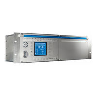
MR TAPCON 260 Operating Instructions Manual (168 pages)
Voltage Regulator
Brand:
MR
| Category:
Controller
| Size: 8.34 MB
Table of Contents
Table of Contents
3
1 Introduction
9
Manufacturer
9
Subject to Change Without Notice
9
Completeness
9
Supporting Documents
9
Safekeeping
10
Notation Conventions
10
Hazard Communication System
10
Information System
11
Typographic Conventions
11
2 Safety
12
General Safety Information
12
Appropriate Use
12
Inappropriate Use
12
Personnel Qualification
13
Operator's Duty of Care
13
3 Product Description
14
Scope of Delivery
14
Function Description of the Voltage Regulation
14
Performance Features
15
Operating Modes
15
Hardware
16
Name Plate
17
Operating Controls
17
Display Elements
18
Serial Interface
21
Assemblies
21
4 Mounting
30
Preparation
30
Mounting Device
30
Connecting Device
31
Cable Recommendation
31
Information about Laying Fiber-Optic Cable
33
Electromagnetic Compatibility
33
Connecting Cables to the System Periphery
37
Wiring Device
37
Checking Functional Reliability
38
5 Commissioning
39
Setting the Display Contrast
39
Setting Parameters
39
Setting the Language
40
Setting Date and Time
40
Setting Further Parameters
41
Function Tests
42
Checking Control Functions
43
Checking Additional Functions
44
Checking Parallel Operation of Several Banks of Transformers
47
6 Functions and Settings
52
Key Lock
52
Carrying out Tap-Change Operation Manually
52
General
52
Setting Device ID
53
Setting the Baud Rate
53
Setting the Voltage Display Kv/V
54
Setting Current Display Unit
54
Setting the Switching Pulse Time
54
Configuring Control Inputs IO1-X1:33/31
56
Configuring Output Relays IO1-X1:25/26 and IO1-X1:23/24
57
Dimming Display
58
Setting Motor Runtime Monitoring
59
Swapping Tapping Direction
61
Normset
61
Control Parameters
63
Setting Desired Value 1
65
Bandwidth
66
Setting Delay Time T1
66
Setting Control Response T1
67
Setting Delay Time T2
68
Limit Values
68
Activating/Deactivating Absolute or Relative Limit Values
69
Setting Undervoltage Monitoring V
69
Setting Overvoltage Monitoring V
72
Setting Overcurrent Monitoring I
74
Activating/Deactivating Function Monitoring
75
Compensation
75
R&X Compensation
75
Z Compensation
78
Cross-Monitoring
79
Setting Desired Value for Regulator 2
80
Setting Undervoltage Limit Value V< for Regulator 2
81
Setting Overvoltage Limit Value V> for Regulator 2
82
Setting Delay Time for Error Message
83
Setting Transformer for Regulator 2
83
Transformer Data
84
Setting the Primary Transformer Voltage
85
Setting the Secondary Transformer Voltage
85
Setting Primary Transformer Current
86
Setting the Current Transformer Connection
87
Setting the Phase Difference for the Current Transformer/Voltage Transformer
87
Parallel Operation of Several Banks of Transformers
91
Assigning CAN Bus Address
91
Selecting Parallel Operation Method
92
Selecting Parallel Operation Control
95
Setting Delay Time for Parallel Operation Error Messages
95
Deactivating Parallel Operation
96
Analog Tap Position Capture (Optional)
96
Setting Lower Limit Value
96
Setting Upper Limit Value
97
LED Selection
98
Measuring Transducer Function
100
Linking Measured Value with Output
100
Assigning Minimum Physical Parameter
100
Assigning Maximum Physical Parameter
101
Assigning Minimum Absolute Value
101
Assigning Maximum Absolute Value
102
Memory (Optional)
102
Setting Undervoltage Threshold
103
Setting Overvoltage Threshold
104
Setting Time Difference of Average Value Interval
105
Setting Event Memory Size
106
Time Plotter
109
Communication Interface SID
115
Assigning a Network Mask
115
Assigning Network Address
115
Entering the Time Server Address
116
Entering Gateway
116
Entering IED Name
117
Communication Interface CIC2 (Optional)
117
Selecting the Communication Port
117
Selecting Communication Baud Rate
118
Assigning Network Address
118
Assigning the TCP Port
119
Setting the Transmission Delay Time for the RS485 Interface
119
Displaying Information about Device
120
Displaying the Info Screen
120
Displaying Measured Values
120
Carrying out LED Test
121
Displaying Input/Output Status
121
Displaying UC Card Status
122
Resetting Parameters
123
Displaying Real-Time Clock
123
Displaying Parallel Operation
123
Displaying Data on CAN Bus
123
Displaying Measured Value Memory
125
Displaying Peak Memory
125
Displaying CIC Card SCADA Information
126
Displaying Upcoming Messages
126
7 Control System Protocol
127
Protocol Specification
127
Downloading ICD File
127
Data Points
128
LPHD - Physical Device
128
LLN0 - Logical Node
129
ATCC1 - Automatic Tap Changer Controller
129
Yltc1
131
Yltc2
132
Yltc3
132
GGIO1 - Generic Process I/O
133
GGIO2 - Generic Process I/O
134
GGIO3 - Generic Process I/O
135
GGIO4 - Generic Process I/O
135
GGIO7 - Generic Process I/O
136
8 Maintenance and Care
138
9 Fault Elimination
139
General Faults
139
No Regulation in AUTO Mode
139
Man-Machine Interface
140
Incorrect Measured Values
140
Parallel Operation Faults
141
Tap Position Capture Incorrect
142
Other Faults
142
10 Messages
144
Signal Inputs
144
Signal Outputs
144
Event Messages
145
11 Disposal
147
12 Overview of Parameters
148
13 Technical Data
152
Indicator Elements
152
Power Supply
152
Voltage Measurement and Current Measurement
154
Digital Inputs and Outputs
155
Analog Inputs and Outputs
156
Control Voltage Supply (Optional)
156
Central Processing Unit
158
System Networking
158
Dimensions and Weight
159
Ambient Conditions
161
Tests
161
Electrical Safety
161
EMC Tests
161
Environmental Durability Tests
161
Glossary
163
List of Key Words
164
Tapcon
165
Advertisement
MR TAPCON 260 Operating Instructions Manual (20 pages)
Voltage regulator
Brand:
MR
| Category:
Controller
| Size: 4.33 MB
Table of Contents
Table of Contents
3
Introduction
9
Manufacturer
9
Subject to Change Without Notice
9
Completeness
9
Supporting Documents
10
Safekeeping
10
Notation Conventions
10
Abbreviations Used
11
Hazard Communication System
12
Information System
13
Safety
15
General Safety Information
15
Appropriate Use
15
Inappropriate Use
16
Personnel Qualification
16
Operator Duty of Care
16
Product Description
19
Advertisement
Related Products
MR tapcon 240
MR TAPCON 230
MR tapcon 230 pro
MR TAPCON 250
MR TAPCON 230 basic
MR TAPCON 230 AVT
MR TAPCON 230 VC
MR TAPCON
MR TAPCON 230 Expert
MR TAPCON LV
MR Categories
Industrial Equipment
Controller
Measuring Instruments
Thermometer
Control Systems
More MR Manuals
Login
Sign In
OR
Sign in with Facebook
Sign in with Google
Upload manual
Upload from disk
Upload from URL