
Related Manuals for MR TAPCON 260


Summary of Contents for MR TAPCON 260
- Page 1 Voltage Regulator TAPCON® 260 Operating Instructions 2374092/04 EN . Bank Parallel Operation with IEC 61850...
- Page 2 © All rights reserved by Maschinenfabrik Reinhausen Dissemination and reproduction of this document and use and disclosure of its content are strictly prohibited unless expressly permitted. Infringements will result in liability for compensation. All rights reserved in the event of the granting of patents, utility models or designs.
-
Page 3: Table Of Contents
Table of contents Table of contents Introduction ......................... 9 Manufacturer ............................9 Subject to change without notice ......................9 Completeness............................9 Supporting documents......................... 9 Safekeeping............................10 Notation conventions ......................... 10 1.6.1 Hazard communication system ........................... 10 1.6.2 Information system .............................. 11 1.6.3 Typographic conventions ............................ - Page 4 Table of contents 4.3.2 Information about laying fiber-optic cable......................33 4.3.3 Electromagnetic compatibility ..........................33 4.3.4 Connecting cables to the system periphery ......................37 4.3.5 Wiring device ............................... 37 4.3.6 Checking functional reliability ..........................38 Commissioning ......................... 39 Setting the display contrast ....................... 39 Setting parameters ..........................
- Page 5 Table of contents 6.5.5 Setting delay time T2............................68 Limit values............................68 6.6.1 Activating/deactivating absolute or relative limit values ..................69 6.6.2 Setting undervoltage monitoring V< ........................69 6.6.3 Setting overvoltage monitoring V> ........................72 6.6.4 Setting overcurrent monitoring I> ........................74 6.6.5 Activating/deactivating function monitoring ......................
- Page 6 Table of contents 6.13.4 Assigning minimum absolute value ........................101 6.13.5 Assigning maximum absolute value ........................102 6.14 Memory (optional)..........................102 6.14.1 Setting undervoltage threshold.......................... 103 6.14.2 Setting overvoltage threshold ..........................104 6.14.3 Setting time difference of average value interval ....................105 6.14.4 Setting event memory size ..........................
- Page 7 Table of contents 7.1.1 Downloading ICD file ............................127 Data points ............................128 7.2.1 LPHD - Physical device ............................. 128 7.2.2 LLN0 - Logical node ............................129 7.2.3 ATCC1 - Automatic tap changer controller......................129 7.2.4 YLTC1 ................................131 7.2.5 YLTC2 ................................
- Page 8 Table of contents 13.5 Analog inputs and outputs ....................... 156 13.6 Control voltage supply (optional) ..................... 156 13.7 Central processing unit ........................158 13.8 System networking .......................... 158 13.9 Dimensions and weight ........................159 13.10 Ambient conditions .......................... 161 13.11 Tests ..............................
-
Page 9: Introduction
1 Introduction Introduction This technical file contains detailed descriptions on the safe and proper in- stallation, connection, commissioning and monitoring of the product. It also includes safety instructions and general information about the prod- uct. This technical file is intended solely for specially trained and authorized per- sonnel. -
Page 10: Safekeeping
1 Introduction Safekeeping This technical file and all supporting documents must be kept ready at hand and accessible for future use at all times. Notation conventions This section contains an overview of the symbols and textual emphasis used. 1.6.1 Hazard communication system Warnings in this technical file are displayed as follows. -
Page 11: Information System
1 Introduction Pictograms warn of dangers: Pictogram Meaning Warning of a danger point Warning of dangerous electrical voltage Warning of combustible substances Warning of danger of tipping Table 2: Pictograms used in warning notices 1.6.2 Information system Information is designed to simplify and improve understanding of particular procedures. -
Page 12: Safety
2 Safety Safety General safety information The technical file contains detailed descriptions on the safe and proper in- stallation, connection, commissioning and monitoring of the product. ▪ Read this technical file through carefully to familiarize yourself with the product. ▪ Particular attention should be paid to the information given in this chap- ter. -
Page 13: Personnel Qualification
2 Safety Personnel qualification The product is designed solely for use in electrical energy systems and facili- ties operated by appropriately trained staff. This staff comprises people who are familiar with the installation, assembly, commissioning and operation of such products. Operator's duty of care To prevent accidents, disruptions and damage as well as unacceptable ad- verse effects on the environment, those responsible for transport, installa-... -
Page 14: Product Description
This chapter contains an overview of the design and function of the product. Scope of delivery The following items are included in the delivery: ▪ TAPCON® 260 ▪ CD MR-Suite (contains the TAPCON®-trol program) ▪ Technical files ▪ Serial cable RS232 ▪... -
Page 15: Performance Features
3 Product description Performance features The TAPCON® 260 is responsible for controlling tapped transformers in a bank of transformers. Apart from control tasks, the TAPCON® 260 provides additional functions such as: ▪ Integrated protective functions: – Undervoltage blocking and overvoltage blocking –... -
Page 16: Hardware
3 Product description Local mode (LOCAL) There is no active management by a superordinate control system in this op- erating mode. Remote mode (REMOTE) In remote mode, you can perform commands using an external control level. In this case, manual operation of the keys is disa- bled. -
Page 17: Name Plate
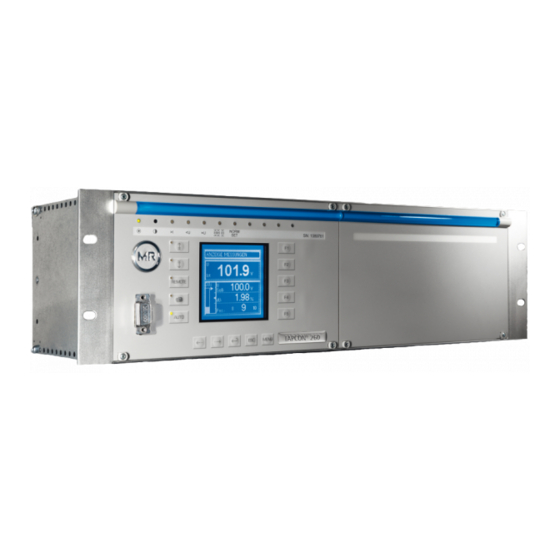
3 Product description Figure 2: Front view Operating panel with display 19-inch plug-in housing (in ac- and LEDs cordance with DIN 41494 Part Rack for optional expansions Name plate 3.5.1 Name plate The name plate is on the outside of the device: Figure 3: Name plate 3.5.2 Operating controls... -
Page 18: Display Elements
3 Product description Figure 4: Operating controls RAISE key: Sends control command for raise tap-change to the motor-drive unit in manual mode. See also [► 52]. LOWER key: Sends control command for lower tap-change to the motor-drive unit in manual mode. See also [►... - Page 19 3 Product description Figure 5: Display elements Operating status LED, green Motor protective switch LED, yellow Overcurrent blocking LED, red Master LED, green/yellow/red Undervoltage blocking LED, Graphics display Overvoltage blocking LED, Auto mode active LED Parallel operation active LED, Manual mode active LED green NORMset active LED , green Remote operating mode ac-...
- Page 20 3 Product description Display Figure 6: Display Status line Bandwidth (upper and lower limit) Measured voltage U Time bar for delay time T1 Reference voltage U Highlighting for measured voltage U Other measured values (use Highlighting for reference volt- age U to switch between them) Current tap position ED1,...
-
Page 21: Serial Interface
3 Product description Unit Measured value Phase Phase angle Active factor: Cosine φ [phi] (output factor) Table 5: Measured value display Status line Current messages and events are displayed in the status line . You can find more information about messages and events in the Messages [►... - Page 22 3 Product description Card Default/option Max. number Option Option Option 1, optional with extension module Option Standard Standard Standard Standard Standard 3, 4 (for SID) Table 6: Assemblies The functions of the assemblies are described in the following sections. You can find more information about the assemblies in the Technical data [►...
- Page 23 3 Product description Figure 9: SUM-P card Figure 10: SUL-P card 3.5.5.2 Voltage measurement and current measurement To measure voltage and current, the device can be equipped with the as- sembly MI or MI3-G: ▪ MI: 1-phase measurement of voltage and current ▪...
- Page 24 3 Product description Figure 11: MI-1 card Figure 12: MI3G card 3.5.5.3 Digital inputs and outputs To record and output digital signals, the device may be equipped with the following assemblies: ▪ IO card ▪ UC card IO card The IO card contains 9 digital inputs and 8 digital potential-free outputs. 5 outputs take the form of change-over contacts.
- Page 25 3 Product description Figure 13: IO card UC card The UC card contains 10 digital inputs and 10 digital potential-free outputs. The device can be equipped with several UC cards (UC1, UC2...). Figure 14: UC1 card 3.5.5.4 Analog inputs and outputs To record and output analog signals, the device may be equipped with the following assemblies: ▪...
- Page 26 3 Product description ▪ Resistance measurement (50...2 000 Ω) Figure 15: AD card Only use the R8/R12 and R42/R46 rotary potentiometers to calibrate the re- sistance measurement. AD8 card The analog input card has 8 inputs that can record the analog signals (4...20mA).
- Page 27 3 Product description Figure 17: AN card 3.5.5.5 Control voltage supply An additional non-regulated control voltage of 60 V DC can be created with the AC card if your system does not have external DC voltage as the signal voltage for the device's digital inputs. Depending on device configuration, one of the following two variants can be fitted: ▪...
- Page 28 3 Product description Figure 19: AC115 card 3.5.5.6 Central processing unit The CPU card is the device's central computing unit. All internal device func- tions and the application functions, such as processing measured values, are controlled and monitored by the CPU card. The CPU card contains a flash memory (optional measured value memory) as a non-volatile data storage in which the operating data such as measured values or events are stored.
- Page 29 3 Product description CIC card As an option, the device can be equipped with up to 2 CIC cards. The CIC cards are used to communicate using a control system protocol or TAPCON®-trol software (CIC2). Figure 21: CIC card RS232 TxD LED for transmit signal RS485 RxD LED for receive signal...
-
Page 30: Mounting
4 Mounting Mounting This chapter describes how to correctly mount and connect the device. Note the connection diagrams provided. Electric shock WARNING Risk of fatal injury due to electrical voltage. ► De-energize the device and system peripherals and lock them to pre- vent them from being switched back on. -
Page 31: Connecting Device
4 Mounting Place device in 19" frame and screw down. Figure 23: Example of device mounting in a 19" frame Connecting device The following section describes how to establish the electrical connection to the device. Electric shock WARNING Risk of fatal injury due to connection mistakes ►... - Page 32 4 Mounting Cable Card Terminal Cable type Conductor Max. length cross-sec- tion Power supply X1:1/2 Unshielded 1.5 mm² Voltage MI/MI1 Shielded 1.5 mm² measurement Current MI/MI1 5/6/9/10 Unshielded 4 mm² measurement Relay* X1:1...10 Unshielded 1.5 mm² X1:19...26 Relay* X1:1...10 Unshielded 1.5 mm²...
-
Page 33: Information About Laying Fiber-Optic Cable
4 Mounting 4.3.2 Information about laying fiber-optic cable To ensure the smooth transfer of data via the fiber-optic cable, you must en- sure that mechanical loads are avoided when laying the fiber-optic cable and later on during operation. Please note the following: ▪... - Page 34 4 Mounting Figure 24: Recommended wiring Cable duct for lines causing Cable duct for lines suscepti- interference ble to interference Interference-causing line (e.g. Line susceptible to interfer- power line) ence (e.g. signal line) ▪ Short-circuit and ground reserve lines. ▪ The device must never be connected using multi-pin collective cables.
- Page 35 4 Mounting Figure 25: Recommended connection of the shielding Connection of the shielding Shielding connection covering using a "pigtail" all areas 4.3.3.3 Wiring requirement in control cabinet Note the following when wiring the control cabinet: ▪ The control cabinet where the device will be installed must be prepared in accordance with EMC requirements: –...
- Page 36 4 Mounting Figure 26: Ground strap connection 4.3.3.4 Information about shielding the CAN bus In order for the CAN bus to operate faultlessly, you have to connect the shielding using one of the following variants. If you are not able to use any of the variants detailed below, we recommend using fiber optic cables.
-
Page 37: Connecting Cables To The System Periphery
4 Mounting Variant 2: The connected devices have different potential Note that the shielding is less effective with this variant. If the devices to be connected have different potential, proceed as follows: ► Connect CAN bus cable's shielding to just one device. Connecting shielding Connect the CAN bus cable's shielding to the intended point on the CPU card using the cable clips provided:... -
Page 38: Checking Functional Reliability
Check the following: ▪ Once you have connected the device to the grid, the screen displays the MR logo and then the operating screen. ▪ The green Operating display LED top left on the device's front panel lights up. -
Page 39: Commissioning
5 Commissioning Commissioning You need to set several parameters and perform function tests before com- missioning the device. These are described in the following sections. NOTICE Damage to device and system periphery An incorrectly connected device can lead to damages in the device and sys- tem periphery. -
Page 40: Setting The Language
5 Commissioning 5.2.1 Setting the language You can use this parameter to set the display language for the device. The following languages are available: English Italian German Portuguese French Russian Spanish To set the language, proceed as follows: > Configuration > General. -
Page 41: Setting Further Parameters
5 Commissioning Date To set the date, proceed as follows: > Configuration > Continue > Memory > Press until the desired display appears. ð Date Press to highlight a digit. ð The desired position is highlighted and the value can be changed. Press to increase the value or to reduce it. -
Page 42: Function Tests
5 Commissioning Setting line drop compensation (optional) If you need line drop compensation, you must set all important parameters for this: Select the LDC compensation method [► 75]. Set the line data for the ohmic voltage drop Ur [► 77]. Set the line data for the inductive voltage drop Ux [►... -
Page 43: Checking Control Functions
5 Commissioning 5.3.1 Checking control functions This section describes how you can check the device's control functions: ü Supply voltage must be present. ü All motor-drive units must be in the same tap position. Press to select manual mode. Set transmission ratio for voltage transformer, current transformer and measuring set-up. -
Page 44: Checking Additional Functions
5 Commissioning 19. Press to select auto mode. ð After 20 seconds, the device lowers the on-load tap-changer one step and after another 10 seconds another step. 20. Press to select manual mode. 21. Set delay time T1 [► 66] and delay time T2 [►... - Page 45 5 Commissioning Reset the operating values for desired value 1 and undervoltage U< [%] to the desired operating values. ð The function test for undervoltage blocking is complete. Checking overvoltage blocking U> Press to select manual mode. Set overvoltage U> [%] to 115 % [►...
- Page 46 5 Commissioning Checking line drop compensation If you want to use line drop compensation, you need to run this function test. A load current of ≥ 10 % of the nominal transformer current is needed for the following function tests. Before the function test, ensure that all parameters for line drop compensation [►...
-
Page 47: Checking Parallel Operation Of Several Banks Of Transformers
5 Commissioning If the control deviation appears in the opposite direction, change the polarity of the current transformer. Set the Z compensation and Z compensation limit value parameters to the desired operating values. ð The function test for Z compensation is complete. Also refer to 2 Setting Z compensation [►... - Page 48 5 Commissioning On one of the two transformers, raise the tap position of the on-load tap- changer by one setting; on the second transformer, lower the tap posi- tion of the on-load tap-changer by one setting. ð The two devices must still be in a state of equilibrium. Adjust the circulating reactive current sensitivity until the result dis- played exceeds the set value for the bandwidth by approx.
- Page 49 5 Commissioning The circulating reactive current blocking parameter should be re- duced [► 93] from the set value of 20 % in steps of 1 % until the Par- allel operation error: circulating reactive current limit exceeded is dis- played. The Parallel operation LED lights up when the circulating reactive ð...
- Page 50 5 Commissioning Compare the tap position displays of devices . All devices must display the same tap position, if not switch them into the same one. Figure 31: Comparing tap positions Master Tap position display Follower To perform the function test, proceed as follows: Press on the follower to select manual mode.
- Page 51 5 Commissioning Press several times on the follower to manually increase the tap position by the number of permitted steps (maximum permitted tap dif- ference) and then one more step. ð After expiry of the set delay time for parallel operation errors, the following error messages are displayed on the master: Parallel op- eration error: tap difference to follower ð...
-
Page 52: Functions And Settings
6 Functions and settings Functions and settings This chapter describes all the functions and setting options for the device. Key lock The device is equipped with a key lock to prevent unintentional operation. You can only set or change the parameters when the key lock is deactivated in manual mode. -
Page 53: Setting Device Id
6 Functions and settings 6.3.1 Setting device ID You can use the device ID parameter to assign a 4-digit ID to the device. This ID is used to uniquely identify the device in the TAPCON®-trol software. To set the device ID, proceed as follows: >... -
Page 54: Setting The Voltage Display Kv/V
6 Functions and settings 6.3.3 Setting the voltage display kV/V This parameter sets how the measured voltage is displayed and used. You can select the following options: ▪ V: The secondary voltage of the system's voltage transformer is dis- played in V and is the reference value for the control parameters. ▪... - Page 55 6 Functions and settings If you set the switching pulse time to 0 s, the motor-drive unit is activated with a continuous signal. The signal then remains active for as long as the keys are pressed. Switching pulse in normal If you set the switching pulse time to 1.5 seconds for example, after the set mode delay time T1 or delay time T2...
-
Page 56: Configuring Control Inputs Io1-X1:33/31
Configuring control inputs IO1-X1:33/31 Depending on your device configuration, the following parameters can be used by MR for special functions. In this case, these parameters are pre-as- signed. You may not be able to view or freely assign these parameters. -
Page 57: Configuring Output Relays Io1-X1:25/26 And Io1-X1:23/24
Configuring output relays IO1-X1:25/26 and IO1-X1:23/24 Depending on your device configuration, the following parameters can be used by MR for special functions. In this case, these parameters are pre-as- signed. You may not be able to view or freely assign these parameters. -
Page 58: Dimming Display
6 Functions and settings You can use this parameter to assign the freely configurable output relay messages which are to be issued. You can assign the following messages: Parameter Messages No function selected Master/Follower Assign Master/Follower message. Local/Remote Assign Local/Remote message. Undervoltage Assign Undervoltage blocking message. -
Page 59: Setting Motor Runtime Monitoring
6 Functions and settings Press > Configuration > General > until the desired parameter is displayed. ð Display off. Press to activate/deactivate automatic dimming. Press Automatic dimming is set. ð 6.3.9 Setting motor runtime monitoring You can use this motor runtime parameter to set the motor runtime. The mo- tor-drive unit's runtime can also be monitored by the device. - Page 60 6 Functions and settings Figure 41: Wiring for motor runtime monitoring Motor running control input Motor protective switch output relay I/O (optional) Motor protective switch trig- Motor-drive unit runtime ex- gered control input I/O (op- ceeded output relay I/O (op- tional) tional) If you want to use the output relay, the feedback from the motor-drive unit...
-
Page 61: Swapping Tapping Direction
6 Functions and settings Press ð The motor runtime is set. 6.3.10 Swapping tapping direction Depending on your configuration, with this parameter, you can set how the device behaves in the event of a raise or lower tap change. This parameter is taken into account in the parallel operation method "tap synchronization"... - Page 62 6 Functions and settings Line drop compensation cannot be performed in NORMset mode. Set the following parameters to operate the device in NORMset mode. Activating/deactivating NORMset You can use this parameter to activate NORMset mode. A manual tap-change operation is required to activate NORMset. This is how the voltage regulator determines the bandwidth required.
-
Page 63: Control Parameters
6 Functions and settings > NORMset > Press until the desired parameter is dis- played. ð Secondary voltage. Press to increase the value or to reduce it. Press The secondary voltage is set. ð Setting desired value 1 With this parameter, you can set the desired value for automatic voltage reg- ulation. - Page 64 6 Functions and settings Behavior only with delay time T1 If the measured voltage U is within the set bandwidth , no control actual commands are issued to the motor-drive unit for the tap-change operation. Control commands will also not be issued to the motor-drive unit if the meas- ured voltage returns to the tolerance bandwidth within the set delay time .
-
Page 65: Setting Desired Value 1
6 Functions and settings If the measured voltage U deviates from the set bandwidth for a long actual period , a control impulse is output to the motor-drive unit after the set de- lay time T1 . If the measured voltage U is still outside the bandwidth, actual delay time T2... -
Page 66: Bandwidth
6 Functions and settings Options for setting the The device provides the following ways of changing the desired voltage val- desired values ue during operation: ▪ Using the control parameters menu item via the operating screen ▪ Using binary inputs ▪... -
Page 67: Setting Control Response T1
6 Functions and settings Press ð The delay time T1 is set. 6.5.4 Setting control response T1 The control response T1 can be set to linear or integral. Linear control response T1 With linear control response, the device responds with a constant delay time regardless of the control deviation. -
Page 68: Setting Delay Time T2
6 Functions and settings 6.5.5 Setting delay time T2 With this parameter, you can set delay time T2. Delay time T2 is used to compensate for large control deviations faster. The delay time T2 only takes effect if more than one tap-change operation is required to return the voltage to within the set bandwidth. -
Page 69: Activating/Deactivating Absolute Or Relative Limit Values
6 Functions and settings Limit value monitoring is used to reduce damage to the system periphery. The following sections describe how you can set the parameters. 6.6.1 Activating/deactivating absolute or relative limit values You can use this parameter to select either the set relative or absolute limit values. - Page 70 6 Functions and settings Figure 45: Response to value falling below limit value + B %: Upper limit : Measured voltage actual : Desired value Value falls below limit value desired - B %: Lower limit Undervoltage U< message is displayed Set limit value for undervolt- Voltage falls below 30 V...
- Page 71 6 Functions and settings Setting undervoltage V< in V/kV You can use this parameter to set the limit value as an absolute value in V or kV units. If you use the key to change the display to kV, this value re- lates to the primary transformer voltage.
-
Page 72: Setting Overvoltage Monitoring V
6 Functions and settings Setting Function Automatic regulation is blocked. Automatic regulation remains active. Table 14: Behavior To activate/deactivate the undervoltage blocking, proceed as follows: > Parameter > Limit values > Press until the desired parameter is displayed. ð V< blocking. Press for On setting or for Off setting. - Page 73 6 Functions and settings Response to high-speed If the measured voltage U exceeds the set limit value , the red LED U> actual return and associated signaling relay activate. The Overvoltage U> message ap- pears in the display. At the same time, the high-speed return function is acti- vated without delay time T1.
-
Page 74: Setting Overcurrent Monitoring I
6 Functions and settings > Parameter > Limit values > Press until the desired parameter is displayed. Press to increase the value or to reduce it. Press ð The limit value is set. Setting overvoltage V> in V/kV You can use this parameter to set the limit value as an absolute value in V or kV units. -
Page 75: Activating/Deactivating Function Monitoring
6 Functions and settings > Parameter > Limit values > Press until the desired parameter is displayed. If necessary press to select the unit you want: % or A. Press to increase the value or to reduce it. Press ð The limit value is set. - Page 76 6 Functions and settings Figure 47: Equivalent circuit Figure 48: Phasor diagram You can calculate the ohmic and inductive voltage drop using the following formulas. This voltage drop calculation relates to the relativized voltage on the secondary side of the voltage transformer. Formula for calculating the ohmic voltage drop: Formula for calculating the inductive voltage drop: Ohmic resistance load in Ω/km...
- Page 77 6 Functions and settings Inductive resistance load in Ω/km per phase Length of line in km Nominal current factor 6.7.1.1 Setting the ohmic voltage drop Vr You can use this parameter to set the ohmic voltage drop (ohmic resistance load). If you do not want to use line drop compensation, you have to set the value 0.0 V.
-
Page 78: Z Compensation
6 Functions and settings Press ð The inductive voltage drop Vx is set. 6.7.2 Z compensation To keep the voltage constant for the consumer, you can use Z compensation to activate a current-dependent increase in voltage. You can also define a limit value to avoid excess voltage on the transformer. -
Page 79: Cross-Monitoring
6 Functions and settings 6.7.2.1 Setting Z compensation This parameter sets the voltage increase ∆V previously calculated. If you do not want to use Z compensation, you have to set the value 0.0 %. To set the Z compensation, proceed as follows: >... -
Page 80: Setting Desired Value For Regulator 2
6 Functions and settings CAN bus Figure 50: Cross-monitoring No measured value or For the check, the measured voltage of the device is transmitted to the measurement card error device via a second separate measurement input and vice versa. The calculated measured voltage is compared with the original measured values via the CAN bus. -
Page 81: Setting Undervoltage Limit Value V< For Regulator 2
6 Functions and settings Volts (V) Kilovolts (kV) This value relates to the secondary This value relates to the primary voltage of the system's voltage voltage of the system's voltage transformer. transformer. Table 16: Units available If you want to change the display from V to kV, you have to set the trans- former data of the device to be monitored. -
Page 82: Setting Overvoltage Limit Value V> For Regulator 2
6 Functions and settings > Parameter > Cross-monitoring > Press until the de- sired parameter is displayed. ð V< regulator 2. Press to increase the value or to reduce it. Press The undervoltage limit value is set as an absolute value. ð... -
Page 83: Setting Delay Time For Error Message
6 Functions and settings > Parameter > Cross-monitoring > Press until the de- sired parameter is displayed. ð V> regulator 2 Press to increase the value or to reduce it. Press The overvoltage limit value is set as an absolute value. ð... -
Page 84: Transformer Data
6 Functions and settings > Parameter > Cross-monitoring > Press until the de- sired parameter is displayed. ð P.T. prim. voltage reg. 2. Press to highlight the decimal place. ð The decimal place is defined and the value can be changed. Press to increase the value or to reduce it. -
Page 85: Setting The Primary Transformer Voltage
6 Functions and settings Parameter set Measured value display Primary Secon- Primary Trans- Voltage (main Current Current (info voltage dary current former screen) (main screen) screen) voltage connec- tion Secondary volt- Secondary cur- age [V] rent [% of con- nection] Primary voltage Secondary cur- [kV]... -
Page 86: Setting Primary Transformer Current
6 Functions and settings To set the secondary transformer voltage, proceed as follows: > Configuration > Transformer data > Press until the desired parameter is displayed. ð Secondary voltage. Press to highlight the position. ð The desired position is highlighted and the value can be changed. Press to increase the value or to reduce it. -
Page 87: Setting The Current Transformer Connection
6 Functions and settings Press to increase the value or to reduce it. Press ð The primary transformer current is set. 6.9.4 Setting the current transformer connection This parameter can be used to set the current transformer connection. This setting is needed for the device to display the correct secondary current in the info screen. - Page 88 6 Functions and settings Circuit A: 1-phase measurement in 1-phase grid TAPCON® 260 Figure 51: Phase difference 0 1PH ▪ The voltage transformer VT is connected to the outer conductor and neutral conductor. ▪ The current transformer CT is looped into the outer conductor. ▪...
- Page 89 6 Functions and settings Circuit C: TAPCON® 260 Figure 53: Phase difference 0 3PH ▪ The voltage transformer VT is connected to the outer conductors L1 and ▪ The current transformer CT1 is looped into the outer conductor L1 and CT2 into the outer conductor L2.
- Page 90 6 Functions and settings Circuit E TAPCON® 260 Figure 55: Phase difference 30 3PH ▪ The voltage transformer VT is connected to the outer conductors L1 and ▪ The current transformer CT is looped into the outer conductor L2. ▪ The current I is ahead of voltage U by 30°.
-
Page 91: Parallel Operation Of Several Banks Of Transformers
6 Functions and settings > Configuration > Transformer data > Press until the desired parameter is displayed. ð Transformer circuit. Press to select the required phase difference. Press The phase difference is set. ð 6.10 Parallel operation of several banks of transformers In the Parallel operation menu item, you can set the parameters needed for parallel operation of banks of transformers. -
Page 92: Selecting Parallel Operation Method
6 Functions and settings > Configuration > Parallel operation > Press until the desired parameter is displayed. ð CAN address. Press to increase the value or to reduce it. Press ð The CAN bus address is saved. 6.10.2 Selecting parallel operation method You can use this parameter to select a parallel operation method. - Page 93 6 Functions and settings > Configuration > Parallel operation. ð Parallel operation method. Press until circulating reactive current appears in the dis- play. Press The parallel operation method is set. ð When using the circulating reactive current parallel operation method, you have to set the parameters for the circulating reactive current sensitivity and circulating reactive current blocking.
- Page 94 6 Functions and settings To set the blocking limit for the maximum permitted circulating reactive cur- rent, proceed as follows: > Configuration > Parallel operation > Press until the desired parameter is displayed. ð Blocking. Press to increase the value or to reduce it.
-
Page 95: Selecting Parallel Operation Control
6 Functions and settings 6.10.3 Selecting parallel operation control As an option, the device can be fitted with a plug-in card for parallel opera- tion with an existing parallel operation control unit when extending existing systems. You can connect the following parallel operation control units: ▪... -
Page 96: Deactivating Parallel Operation
6 Functions and settings > Configuration > Parallel operation > Press until the desired parameter is displayed. ð Error message. Press to increase the value or to reduce it. Press The delay time for the parallel operation error message is set. ð... -
Page 97: Setting Upper Limit Value
6 Functions and settings For example: To capture a tap position range of 1...19 via input 1 as 4...20 mA, you must set 20 % for the "Input 1 lower limit" parameter and 1.0 for the "Input 1 lower value" parameter. Setting lower limit value of input signal To configure the analog input, you must state the lower limit value of the in- put signal. -
Page 98: Led Selection
6 Functions and settings You can undertake the settings for each input on the analog input card. For example: To capture a tap position range of 1...19 via input 1 as 4...20 mA, you must set 100 % for the "Input 1 upper limit" parameter and 19.0 for the "Input 1 upper value"... - Page 99 6 Functions and settings Depending on your device configuration, the following parameters can be used by MR for special functions. In this case, these parameters are pre-as- signed. You may not be able to view or freely assign these parameters.
-
Page 100: Measuring Transducer Function
6 Functions and settings 6.13 Measuring transducer function Depending on the configuration and version of the measuring transducer module 2 or 4, the transducer module can be used to obtain measured val- ues as analog values in the following ranges: ▪... -
Page 101: Assigning Maximum Physical Parameter
6 Functions and settings To assign the lower physical parameter to the measuring transducer, pro- ceed as follows: Press > Configuration > Continue > Continue > Measuring transducer 1 / 2 > until the desired parameter is dis- played. Output 1 bottom. ð... -
Page 102: Assigning Maximum Absolute Value
6 Functions and settings 6.13.5 Assigning maximum absolute value In this display you can assign a maximum limit value to the measuring trans- ducer output as an absolute value. To assign the maximum absolute value, proceed as follows: > Configuration > Continue >... -
Page 103: Setting Undervoltage Threshold
6 Functions and settings As soon as there is no more free space in the event memory, the oldest val- ues are overwritten by the new values measured. You can access informa- tion about the current event memory content via the Info [►... -
Page 104: Setting Overvoltage Threshold
6 Functions and settings Relative value To set the undervoltage threshold, proceed as follows: > Configuration > Continue > Continue > Memo- ð V< threshold. Press to increase the value or to reduce it. Press The undervoltage threshold is set. ð... -
Page 105: Setting Time Difference Of Average Value Interval
6 Functions and settings Relative value To set the overvoltage threshold, proceed as follows: > Configuration > Continue > Continue > Memo- ry > Press until the desired parameter is displayed. ð V> threshold. Press to increase the value or to reduce it. -
Page 106: Setting Event Memory Size
6 Functions and settings To set the average value interval, proceed as follows: > Configuration > Continue > Continue > Memo- ry > Press until the desired parameter is displayed. Average value interval. ð Press to increase the time or to reduce it. - Page 107 6 Functions and settings Figure 68: Event duration (more than 5 minutes) Saving at high resolution Event occurs (voltage departs from bandwidth) Saving at low resolution Event occurs (voltage returns to bandwidth) Run-in time/overrun time; du- End of event's overrun time ration: 10 seconds Start of event's run-in time Event lasting more than 5 minutes...
- Page 108 6 Functions and settings Figure 69: Event duration (more than 5 minutes) High-resolution recording Event occurs (voltage departs from bandwidth) Low-resolution recording End of high-resolution record- ing; start of low-resolution re- cording Duration: 10 seconds Start of event's run-in time Duration of high-resolution re- Event occurs (voltage returns cording: 5 minutes...
-
Page 109: Time Plotter
6 Functions and settings When you set the event memory size, the complete memory is cleared as soon as you confirm the change. To set the event memory size, proceed as follows: > Configuration > Continue > Continue > Memo- ry >... - Page 110 6 Functions and settings Symbols Figure 70: Time plotter symbols Move time axis back Select values to set Move time axis forward Decrease set values by one unit Increase set values by one unit Desired/actual voltage value display Figure 71: Desired/actual value Set desired voltage value dis- Actual voltage value display play...
- Page 111 6 Functions and settings Overvoltage/undervoltage display Figure 72: Overvoltage/undervoltage Overvoltage bar/undervoltage Upper voltage value Lower voltage value 6.14.5.2 Moving time axis You can set the reporting times in the setting box in the time plotter. Refer to the table for the time axis division and the resulting duration of the range shown.
- Page 112 6 Functions and settings Figure 73: Time axis Horizontal grid lines (the set Setting box for reporting times reporting time range is be- displayed tween the horizontal grid lines) To undertake settings, proceed as follows: > Info > Press until the desired display appears. ð...
- Page 113 6 Functions and settings Figure 74: Voltage range Horizontal grid lines (the set Setting box for voltage range voltage range is between the displayed horizontal grid lines) To set the voltage range, proceed as follows: > Info > Press until the desired display appears. ð...
- Page 114 6 Functions and settings Figure 75: Retrace time Time To move the sequence to a precise time, proceed as follows: > Info > Press until the desired display appears. ð Time plotter. Press until the setting box for the retrace time is highlighted. ð...
-
Page 115: Communication Interface Sid
6 Functions and settings To move the sequence to a precise time, proceed as follows: > Info > Press until the desired display appears. ð Time plotter. Press until the setting box for the retrace date is highlighted. ð The setting box is now highlighted and the value can be changed. Press to advance the date by one digit or to move it back one... -
Page 116: Entering The Time Server Address
6 Functions and settings Press > Configuration > General > until the desired parameter is displayed. ð Network address. Press in order to highlight the position. ð The desired position is highlighted and the value can be changed. Press to increase the value or to reduce it. -
Page 117: Entering Ied Name
6 Functions and settings Press > Configuration > General > until the desired parameter is displayed. ð Gateway. Press in order to highlight the position. ð The desired position is highlighted and the value can be changed. Press to increase the value or to reduce it. -
Page 118: Selecting Communication Baud Rate
6 Functions and settings ▪ Fiber-optic cable You can only select one communication port. All remaining ports remain dis- abled. It is not possible to use several communication ports at the same time. To select the communication port, proceed as follows: >... -
Page 119: Assigning The Tcp Port
6 Functions and settings To assign the network address, proceed as follows: > Configuration > Continue > Continue > Con- tinue > Comm. interface 2 > Press until the desired parameter is displayed. Network address CIC2. ð Press to highlight the desired position. ð... -
Page 120: Displaying Information About Device
6 Functions and settings > Configuration > Continue > Continue > Con- tinue > Comm. interface 2 > Press until the desired parameter is displayed. ð Transmission delay CIC 2. Press to increase the value or to reduce it. Press ð... -
Page 121: Carrying Out Led Test
6 Functions and settings ► > Info > Press until the desired measurement parameter is displayed. ð Measured values. 6.17.3 Carrying out LED test You can check whether the LEDs are functioning properly. To do this, press the relevant function key to illuminate an LED: LED no. -
Page 122: Displaying Uc Card Status
6 Functions and settings Figure 82: Signals Signaling status Control inputs/output relays To query the status, proceed as follows: ► Press > Info > until the desired measurement parameter is displayed. INPUT/OUTPUT STATUS. ð 6.17.5 Displaying UC card status The status of the respective optocoupler inputs is shown in this display . As soon as a continuous signal is present at the input, it is shown in the display with a 1. -
Page 123: Resetting Parameters
6 Functions and settings 6.17.6 Resetting parameters With this display you can reset your settings to the factory settings . It also shows whether all parameters are saved correctly. Resetting the parameters to the factory settings permanently deletes your settings. To reset all the set parameters, proceed as follows: Press >... - Page 124 6 Functions and settings Figure 84: CAN bus data CAN bus address of device Reactive current in % Voltage in V Current tap position Active current in % Figure 85: Other CAN bus data Group input 1 Follower tap synchronization (0 = deactivated;...
-
Page 125: Displaying Measured Value Memory
6 Functions and settings 6.17.10 Displaying measured value memory As an option, the device can be equipped with a long-term memory module. You can display information about the memory in this window. To display the measured value memory, proceed as follows: ►... -
Page 126: Displaying Cic Card Scada Information
6 Functions and settings ► Press > Info > until the desired measurement parameter is displayed. ð Peak memory. 6.17.12 Displaying CIC card SCADA information The following information on the SCADA connection is displayed in this CIC card SCADA information display: ▪... -
Page 127: Control System Protocol
7 Control system protocol Control system protocol Protocol specification The device provides an extract of commands and messages from the inter- face protocol IEC 61850 for communication. Device-specific data points You can find the device-specific data points and presettings in the device's ICD file. -
Page 128: Data Points
7 Control system protocol If necessary, confirm the password prompt without entering a password. Figure 87: Downloading the ICD file using an Internet browser Use Save as to download the ICD file (in this example ATCC.ICD). Other files, such as the Model Implementation Conformance Statement, are located in the misc folder and can also be downloaded using Save Data points You will find these abbreviations in the following tables. -
Page 129: Lln0 - Logical Node
7 Control system protocol Attribute name Attribute Explanation M/O/E Remarks type PhyHealth Physical device health Proxy Indicates if this LN is a proxy Table 33: LPHD class (LPHD1) 7.2.2 LLN0 - Logical node Attribute name Attribute Explanation M/O/E Remarks type LLN0 Logical node zero name Data... - Page 130 7 Control system protocol Attribute Attribute Explanation M/O/E/C Remarks name type Follower Follower mode (parallel control) direct-with-normal- security SICmd1 Serial interface command 1 direct-with-normal- security SICmd2 Serial interface command 2 direct-with-normal- security SICmd3 Serial interface command 3 direct-with-normal- security VoltLvl1 Voltage level 1 direct-with-normal- security...
-
Page 131: Yltc1
7 Control system protocol Attribute Attribute Explanation M/O/E/C Remarks name type LDCX Line drop voltage due to line re- Unit: V actance component (voltage) Multiplier: none BlkLV Control voltage below which au- Unit: none to lower commands blocked Multiplier: c (relative) LimLodA Limit load current (LTC block... -
Page 132: Yltc2
7 Control system protocol Attribute name Attribute type Explanation M/O/E Remarks EndPosR End position raise reached EndPosL End position lower reached Settings Table 36: YLTC class 7.2.5 YLTC2 Attribute name Attribute type Explanation M/O/E Remarks YLTC2 OLTC Common logical node information Mode status only Behavior... -
Page 133: Ggio1 - Generic Process I/O
7 Control system protocol Attribute name Attribute type Explanation M/O/E Remarks Behavior Health Health 1 = OK; 2 = signaling YELLOW for TAPGUARD; 3 = no internal communica- tion of parameter error or signaling RED for TAPGUARD NamPlt Name plate Controls TapChg Change tap position... -
Page 134: Ggio2 - Generic Process I/O
7 Control system protocol Attribute Attribute Explanation M/O/E Remarks name type Ind4 IO X1:17 Ind5 IO X1:14 Ind6 IO X1:13 Ind7 IO X1:11 Ind8 IO X1:12 Ind9 IO X1:29 Ind10 IO X1:28 Settings Table 39: GGIO class (GGIO1) 7.2.8 GGIO2 - Generic process I/O Attribute Attribute Explanation... -
Page 135: Ggio3 - Generic Process I/O
7 Control system protocol 7.2.9 GGIO3 - Generic process I/O Attribute Attribute Explanation M/O/E Remarks name type GGIO3 GPIO UC2 Common logical node information Mode status-only Behavior Health Health 1 = OK; 3 = no internal com- munication NamPlt Name plate Controls Measured values Status information... -
Page 136: Ggio7 - Generic Process I/O
7 Control system protocol Attribute Attribute type Explanation M/O/E Remarks name Measured values Status information Ind1 UC3 X1:11 Ind2 UC3 X1:12 Ind3 UC3 X1:14 Ind4 UC3 X1:15 Ind5 UC3 X1:16 Ind6 UC3 X1:17 Ind7 UC3 X1:30 Ind8 UC3 X1:31 Ind9 UC3 X1:32 Ind10 UC3 X1:33... - Page 137 7 Control system protocol Attribute name Attribute type Explanation M/O/E Remarks Ind8 UC4 X1:31 Ind9 UC4 X1:32 Ind10 UC4 X1:33 Settings Table 43: GGIO class (GGIO7) Maschinenfabrik Reinhausen 2014 2374092/04 EN TAPCON® 260...
-
Page 138: Maintenance And Care
8 Maintenance and care Maintenance and care You can clean the device's housing with a dry cloth. TAPCON® 260 2374092/04 EN Maschinenfabrik Reinhausen 2014... -
Page 139: Fault Elimination
9 Fault elimination Fault elimination This chapter describes how to eliminate simple operating faults. General faults Characteristics/detail Cause Remedy No function No power supply Check the power supply Fuse tripped Contact Maschinenfabrik Reinhausen ▪ Operating status LED GmbH does not illuminate Relays chatter Supply voltage too low Check the supply voltage... -
Page 140: Man-Machine Interface
9 Fault elimination Characteristics/detail Cause Remedy Device blocking Tap positions of motor-drive Activate operating mode and perform units ED1, ED2 and ED3 not ▪ Tap difference LED illu- a manual tap-change operation using the same minated keys until the tap position of motor-drive units ED1, ED2 and ED3 have been compared. -
Page 141: Parallel Operation Faults
9 Fault elimination Characteristics/detail Cause Remedy Measured voltage Voltage drop on measuring Check measured voltage at plug terminal lead. MI:01/MI:02. ▪ Measured value too low. Measured voltage Possible sources of fault: Check measured voltage at plug terminal MI:01/MI:02. ▪ Measured value fluctu- ▪... -
Page 142: Tap Position Capture Incorrect
9 Fault elimination Characteristics/detail Cause Remedy Devices have the same CAN Set different CAN bus addresses. bus addresses. Problem with parallel opera- tion ▪ Parallel operation fault LED illuminated Table 48: Parallel operation faults Tap position capture incorrect Characteristics/detail Cause Remedy Step display incorrect. - Page 143 9 Fault elimination Please provide answers to the following questions: ▪ Has a firmware update been carried out? ▪ Has there previously been a problem with this device? ▪ Have you previously contacted Maschinenfabrik Reinhausen about this issue? If yes, then who was the contact? Maschinenfabrik Reinhausen 2014 2374092/04 EN TAPCON®...
-
Page 144: Messages
10 Messages Messages This chapter contains an overview of the device's messages. 10.1 Signal inputs Input Inscription Function UC1/2/3- MOTOR-DRIVE Motor-drive unit is in operation X1:12 UNIT IN OPERA- TION UC1/2/3- MOTOR PROTEC- Motor protective switch has trig- X1:11 TIVE SWITCH OFF gered IO-X1:31 See connection dia-... -
Page 145: Event Messages
10 Messages Relay Inscription Cause IO-X1:20 UNDERVOLT- Signal for undervoltage, overvoltage, overcurrent message OVERVOLTAGE OVERCURRENT IO-X1:23 PARALLEL Signal for parallel operation error mes- FAULT, or: See sage connection dia- gram IO-X1:25 PARALLEL ON, Signal if parallel operation is active or: See connec- tion diagram TAP POSITION BCD signal of tap position... - Page 146 10 Messages Event message Cause Parallel operation error Event message appears with the following causes: ▪ Tap synchronization method – Tap position not the same – No master or more than one master – Invalid tap position – Incorrect parallel operation method se- lected for a device ▪...
-
Page 147: Disposal
11 Disposal Disposal The device was produced in accordance with European Community Direc- tive 2011/65/EC (RoHS) and must be disposed of accordingly. If the device is not operated within the European Union, the national disposal require- ments applicable in the country of use should be observed. Maschinenfabrik Reinhausen 2014 2374092/04 EN TAPCON®... -
Page 148: Overview Of Parameters
12 Overview of parameters Overview of parameters This section contains an overview of the relevant menus and parameters. Parameter Setting range Factory setting Current setting Parameter > Normset Normset activation On/Off Primary voltage 0...9,999 kV 0 kV Secondary voltage 57...125 V 100 V Desired value 1 49...140 V... - Page 149 12 Overview of parameters Parameter Setting range Factory setting Current setting U< regulator 2 34...160 V 60.0 V U< regulator 2 60...100 % 60 % U> regulator 2 34...160 V 140.0 V U> regulator 2 100...140 % 140 % U ref for regulator 2 49...140 V 100.0 V Configuration >...
- Page 150 12 Overview of parameters Parameter Setting range Factory setting Current setting Parallel operation method Off, circulating reactive current; master; follow- er; synch. auto SKB parallel operation On/Off Stability 0...100 % 0.0 % Tapping direction Swapped Standard/Swapped Standard Configuration > Analog inputs (optional) Input 1 upper limit 0...100 % 100.0 %...
- Page 151 12 Overview of parameters Parameter Setting range Factory setting Current setting Output 4 measured value [► 100] Output 4 upper value -9,999...9,999 Output 4 lower value -9,999...9,999 Output 4 upper 1 mA; 10 mA; 20 mA; 20 mA 10 V Output 4 lower [►...
-
Page 152: Technical Data
13 Technical data Technical data 13.1 Indicator elements Display LCD, monochrome, graphics-capable 128 x 128 pixels LEDs 15 LEDs for operation display and messages Table 54: Indicator elements 13.2 Power supply SUH-P Permissible voltage 88...264 V AC range 88...353 V DC : 100...240 V AC : 88...353 V DC Permissible frequency... - Page 153 13 Technical data SUL-P SUM-P Permissible voltage 18...36 V DC 36...72 V DC range Input current Max. 2.3 A Max. 1 A Internal fuse 250 V; 3 A; 6.3 x 32 mm, "fast-acting" character- istics Table 56: Special model Figure 89: Internal fuse of SUM-P card and SUL-P card Fuse Spare fuse Interface...
-
Page 154: Voltage Measurement And Current Measurement
13 Technical data 13.3 Voltage measurement and current measurement MI3-G Measurement 1 phase 3 phase Voltage measure- : 100 V AC ment Measuring range: 85...140 V AC Rated frequency: 45...65 Hz Intrinsic consumption: < 1 VA Measurement category IV in accordance with IEC 61010-2-30 Measuring error: <... -
Page 155: Digital Inputs And Outputs
13 Technical data Interface Description Voltage transformer L1 Voltage transformer L1 Return conductor of current transform- er L1 Current transformer L1 (rated current 5 Voltage transformer L2 Voltage transformer L2 Return conductor of current transform- er L2 Current transformer L2 (rated current 5 Voltage transformer L3 Voltage transformer L3 Return conductor of current transform-... -
Page 156: Analog Inputs And Outputs
13 Technical data Figure 90: Maximum contact loadability of outputs with direct current Ohmic load 13.5 Analog inputs and outputs Channels 2 inputs 8 inputs 2 outputs or 4 outputs (AN + AN1) Input signals 0...±20mA 4...20 mA (depending on 0...±10mA configuration) 0...±10V... - Page 157 13 Technical data AC-115 AC-230 Power consumption 0.16 A 0.08 A Internal fuse 250 V; 3 A; 6.3 x 32 mm, "fast-acting" character- istics Table 63: Control voltage supply Figure 91: Internal fuses of AC-115 card and AC-230 card Fuse Spare fuse Interface Description...
-
Page 158: Central Processing Unit
13 Technical data 13.7 Central processing unit Interface Description GND_ISO CAN_L SHLD* CAN_H Table 66: Terminal X9 (CAN bus) *) Alternatively, you can fit the cable shield to the partition plate's cable clip. 13.8 System networking CIC card RS232 9-pin SUB-D connector RS485 3-pin socket from Phoenix Contact (MC1.5/3 GF 3.5) -
Page 159: Dimensions And Weight
13 Technical data Interface Description GND (100 Ω ground resistance) B (inverted) A (non-inverted) Table 69: Terminal X9 (RS485) Interface Description TxD+ TxD- RxD+ RxD- Table 70: Terminal X7 (RJ45) SID card RJ45 Max. 100 m Ethernet 100 MBit/s Table 71: Technical data for SID card Interface Description TxD+... - Page 160 13 Technical data Figure 92: Dimensions TAPCON® 260 2374092/04 EN Maschinenfabrik Reinhausen 2014...
-
Page 161: Ambient Conditions
13 Technical data 13.10 Ambient conditions Operating temper- -25°C...+70°C ature Storage tempera- -30°C...+85°C ture Table 74: Permissible ambient conditions 13.11 Tests 13.11.1 Electrical safety EN 61010-1 Safety requirements for electrical measurement and control and regulation equipment and laboratory in- struments IEC 61131-2 Dielectric test with operating frequency 2.5 kV / 1 IEC 60255... - Page 162 13 Technical data IEC 60068-2-3 Constant moist heat + 40 °C / 93 % / 4 days, no dew IEC 60068-2-30 Cyclic moist heat (12 + 12 hours) + 55 °C / 93 % / 6 cycles Table 77: Environmental durability tests TAPCON®...
-
Page 163: Glossary
Glossary Glossary Abbreviation for "Deutsches Institut für Normung" Electromagnetic compatibility Abbreviation for "European Norm" International Electrotechnical Commission Line drop compensation Abbreviation for "Maschinenfabrik Reinhausen GmbH" Abbreviation for fiber-optic cable Raise/lower Abbreviation for "Real Time Clock" Maschinenfabrik Reinhausen 2014 2374092/04 EN TAPCON®... -
Page 164: List Of Key Words
List of key words List of key words AC card Cable recommendation Factory setting 123, 148 AD card CAN bus Fiber-optic cable AD8 card Data Information about laying AN card CIC card Function monitoring Analog input CIC card SCADA information 126 Overvoltage limit value Assemblies Circulating reactive current... -
Page 165: Tapcon
List of key words Key lock Parallel operation 91, 123 tap position capture Keys CAN bus Analog Circulating reactive current Tapping direction swapped Parallel operation error mes- TCP port sage Throughput capacity Language Parallel operation method Time LED selection Parallel operation control Time axis Limit value Parallel operation control unit... - Page 166 List of key words Z compensation Activate Limit value TAPCON® 260 2374092/04 EN Maschinenfabrik Reinhausen 2014...
- Page 168 Phone: +60 3 2142 6481 E-Mail: sales@au.reinhausen.com Fax: +60 3 2142 6422 E-Mail: mr_rap@my.reinhausen.com Brazil P.R.C. (China) MR do Brasil Indústria Mecánica Ltda. MR China Ltd. (MRT) Av. Elias Yazbek, 465 CEP: 06803-000 开德贸易(上海)有限公司 Embu - São Paulo 中国上海浦东新区浦东南路 360 号...
Need help?
Do you have a question about the TAPCON 260 and is the answer not in the manual?
Questions and answers