Sign In
Upload
Manuals
Brands
Moons' Manuals
Servo Drives
MBDV-520AC
Moons' MBDV-520AC Manuals
Manuals and User Guides for Moons' MBDV-520AC. We have
1
Moons' MBDV-520AC manual available for free PDF download: Hardware Manual
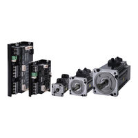
Moons' MBDV-520AC Hardware Manual (181 pages)
Low Voltage Servo System
Brand:
Moons'
| Category:
Servo Drives
| Size: 5.61 MB
Table of Contents
Table of Contents
2
1 Introduction
7
About this Manual
7
MBDV Series Low Voltage Servo Documentation
7
Safety
7
Safety Sign
7
Safety Precautions
8
Storage
8
Installation Precautions
8
Wiring Precautions
8
Precautions During Trial Operation
9
Certified Specifications
9
Maintenance and Inspection
10
Check Items and Cycles
10
Replacement of Parts
10
2 Basic Information
11
Product Confirmation
11
Drive Model Introduction
11
Drive Model Description
11
Drive Specifications
12
Dimensions of the Driver (Unit: MM)
13
Motor Model Introduction
14
Motor Nameplate Description
14
Motor Model Description
14
Motor Specifications and Dimensions
15
General Motor Specifications
20
Brake Specifications
20
3 Installation
21
Storage Conditions
21
Installation Conditions
21
Drive Installation Space
21
Motor Installation Precautions
21
Protection of Encoders and Bearings
21
Precautions for Motor in Oil and Water Environment
22
Wiring
23
Motor Temperature Rise
23
4 System Configuration and Wiring
24
Electromagnetic Compatibility (EMC)
24
Ground
24
Shielding of Motor Cables
25
Ferrite Ring
25
External Circuit Wiring
26
Interface Introduction
26
DIP Switch Function Description
27
Driver Terminal Description
28
Considerations When Wiring
28
Precautions for the Use of Drag Chain Cables
29
Recommended Wires
29
Crimp Terminal
30
Ground Terminal
30
Main & aux - Driver Power Wiring Method
31
Motor Connection Method
31
Block Diagram of the Connection between the Driver and the Motor Power Line
31
Definition of Motor Power Line Wiring
31
Encoder -The Connection Method between the Driver and the Motor Encoder Line
32
The Block Diagram of the Connection between the Driver and the Motor Encoder Line
32
Encoder Pinout
32
Encoder Line Interface Definition
33
Using an Electromagnetic Brake
34
Connection Diagram
34
Precautions for the Use of Brake Motors
34
Brake Action Sequence
35
REG- Regenerative Energy Absorption Resistor Wiring Method
35
Calculation Method of Regenerative Energy
36
Wiring Method
38
Device Setting Parameters
38
Communication Interface
39
USB- Host Computer Debugging Interface
39
Wireless - Host Computer Wireless Debugging Interface
39
COM1/2 - Canopen / RS485 Communication Interface
39
I/O Input and Output Signal Wiring (MBDV-520AC)
40
I/O Input and Output Signal Specifications
40
I/O Signal Pin Block Diagram
40
Input and Output Pinout
41
Input and Output Signals (MBDV-2X-520AC)
45
Input and Output Specifications
45
I/O Signal Pin Block Diagram
46
Input and Output Pinout
47
Encoder Feedback Output
51
STO - Safe Torque off Function
52
Safe Torque off Precautions
52
STO Function Connector
53
5 LED Display
55
Display Content
55
Decimal Point Meaning
55
Alarm Codes and Definitions
55
6 Commissioning
57
Inspection before Commissioning
57
Commissioning Steps
57
Drive Configuration
58
7 Control Modes and Functions
59
I/O Signal Setting
59
Input Signal Configuration
59
Output Signal Configuration
60
Servo Enable
61
Alarm Reset
61
CW, CCW Limit
62
Gain Select
62
Emergency Stop
64
Fault Output
65
Warning Output
66
Motor Brake Control
67
Servo Ready Output
68
Servo-On Status Output
68
Dynamic Position Error Output
69
Software Limit Output
70
Timing Diagram
71
Position Control Mode
72
Position Control Mode Configuration
72
Command Smoothing Filter Setting
74
Positioning Complete Signal
75
Position Reached Output
75
Gain Parameter in Position Mode
76
Velocity Control Mode
77
Velocity Control Mode Configuration
77
Zero Speed Clamp Function
78
Rotation Direction Switch
79
Zero Speed Output
80
Velocity Reached Output
81
Velocity Consistent Output
82
Velocity Control Mode Methods
83
Torque Control Mode
84
Commanded Torque Control
84
Torque Command Filter
84
Speed Limit in Torque Mode
85
Output During Speed Limiting
86
Torque Reaches Output
86
Torque Consistent Output
87
Torque Limit
88
Torque Limiting Methods
88
Torque Limit Reached Output
91
Encoder Feedback Output Function
91
Pulse Frequency Division Output Signal Pin
91
Pulse Frequency Division Output Mode Setting
92
Pulse Output Gear Ratio
93
Dynamic Braking
94
Dynamic Braking When Servo off Signal Triggered
95
Dynamic Braking When Driver Fault Present
95
Home Function
95
Back to the Origin Basic Concept
97
Introduction to the Way of Returning to the Origin
97
8 Parameter Setting
121
Parameter Classification
121
List of Parameters
121
Parameter Description
125
Group P0-XX: PID Gain Setting
125
Group P1-XX: Configuration
131
P2-XX: Trajectory
138
P3-XX Group: Encoder & Step/Dir
143
9 Troubleshooting
150
List of Drive Alarms
150
Driver Alarm Causes and Solutions
152
10 Servo Gain Setting
156
Servo Tuning Process and Mode Introduction
156
Servo Tuning Flow Chart
156
Introduction to Parameter Tuning Mode
157
Tuning Mode
158
Auto Tuning Mode
159
Auto-Tuned Motion Profile Conditions
159
Auto-Tuning Flowchart
160
Start Auto-Tuning -- Software Operation on
161
Advanced Tuning Mode
164
Introduction to Advanced Tuning Mode
164
Parameters in Advanced Tuning Mode
165
Servo System Parameter Description
166
Gain Parameter of Speed Loop
167
Resonance Suppression
168
Torque Command Filter
168
Notch Filters
169
Setting the Notch Filter Manually
171
End Vibration Suppression
178
External Vibration Suppression
179
11 Connect Us
181
Advertisement
Advertisement
Related Products
Moons' MBDV Series
Moons' MBDV-2X-520AC
Moons' MBDV-2X-520AC-F02
Moons' M2DC-10D5S
Moons' M2DC-20D5R
Moons' M2DC-10D5C
Moons' M2DC-20D5D
Moons' MSSTAC5-IP-E-2V
Moons' MCSE5005
Moons' MC Series
Moons' Categories
Servo Drives
DC Drives
Engine
Control Unit
Power Supply
More Moons' Manuals
Login
Sign In
OR
Sign in with Facebook
Sign in with Google
Upload manual
Upload from disk
Upload from URL