Sign In
Upload
Manuals
Brands
Mitsubishi Electric Manuals
Industrial Equipment
NZ2GFCF-D62PD2
Mitsubishi Electric NZ2GFCF-D62PD2 Manuals
Manuals and User Guides for Mitsubishi Electric NZ2GFCF-D62PD2. We have
1
Mitsubishi Electric NZ2GFCF-D62PD2 manual available for free PDF download: User Manual
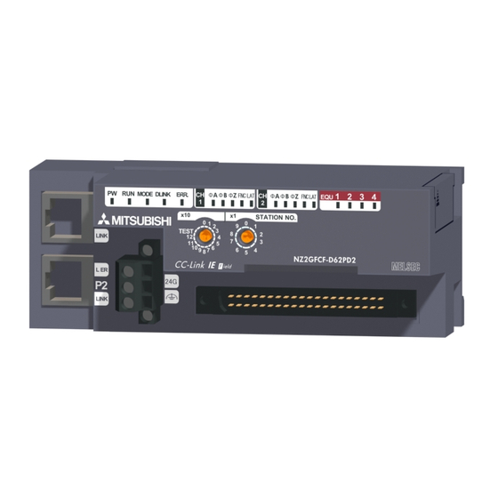
Mitsubishi Electric NZ2GFCF-D62PD2 User Manual (330 pages)
CC-Link IE Field Network High-Speed Counter Module
Brand:
Mitsubishi Electric
| Category:
Industrial Equipment
| Size: 8.6 MB
Table of Contents
Safety Precautions
3
Conditions of Use for the Product
7
Introduction
8
Relevant Manuals
9
Table of Contents
10
Manual Page Organization
14
Term
15
Packing List
17
Chapter 1 High-Speed Counter Module
18
Application
19
Features
20
Chapter 2 Part Names
25
Chapter 3 Specifications
29
General Specifications
29
Performance Specifications
31
The Input Waveform and the Phase Difference between Phase a Pulse and Phase B Pulse
34
Calculating Current Consumption
36
Function List
37
List of Remote I/O Signals
40
List of Remote Register
44
List of Remote Buffer Memory
46
Chapter 4 The Procedure before Operation
54
Chapter 5 System Configuration
56
High-Speed Counter Module System Configuration
56
Applicable Systems
57
Chapter 6 Installation and Wiring
59
Station Number Setting
59
Installation Environment and Installation Position
60
Installation Environment
60
Installation Position
60
Installation Direction
61
Installation
62
Connecting Extension Modules
62
Mounting the Modules on a DIN Rail
64
Wiring with Terminal Block for Module Power Supply and FG
67
Wiring of Ethernet Cable
69
Wiring of Connectors for External Devices
72
Wiring Precautions
72
Connectors for External Devices
74
I/O Interfaces with External Devices
75
Encoders that Can be Connected
80
Wiring Example (between a High-Speed Counter Module and an Encoder)
81
Wiring Example (between a Controller and External Input Terminals)
84
Wiring Example (with Coincidence Output Terminals)
85
Chapter 7 Various Settings
86
Parameter Setting
86
Changing the Parameter
94
Changing the Network Configuration
94
Changing the Parameter Without Changing the Network Configuration
98
Operation Mode List
101
Chapter 8 Functions
103
Mode Shift at Power-On
103
Drive Mode Switch
104
Pulse Input Modes and Counting Methods
106
Types of Pulse Input Modes
106
Counting Method Setting
108
Counter Format Selection
109
Linear Counter Function
109
Ring Counter Function
111
Comparison Output Function
116
Operation Overview of the Coincidence Output Function and the Cam Switch Function
116
Coincidence Output Function
118
Preset/Replace (at Coincidence Output) Function
128
Cam Switch Function
131
Preset/Replace Function
136
Latch Counter Function by Latch Counter Input Terminal
141
Counter Function Selection
143
Count Disable Function
145
Latch Counter Function (Counter Function Selection)
147
Sampling Counter Function
150
Periodic Pulse Counter Function
153
Count Disable/Preset/Replace Function
156
Latch Counter/Preset/Replace Function
158
CC-Link IE Field Network Synchronous Communication Function
161
Frequency Measurement Function
164
Rotation Speed Measurement Function
168
Pulse Measurement Function
172
PWM Output Function
176
Output HOLD/CLEAR Setting Function
183
Cyclic Data Update Watch Function
184
Error Notification Function
185
Function at the Extension Module Installation
188
CC-Link IE Field Network Diagnostic Function
191
Chapter 9 Programming
194
Precautions for Programming
194
Procedure for Programming
196
Program Example
197
Chapter 10 Maintenance and Inspection
221
Chapter 11 Troubleshooting
223
Checking for the Error Codes and the Warning Codes
223
Error Code List
227
Checking the Leds
245
Unit Test
248
Troubleshooting by Symptom
249
When the Setting on the Operation Mode Setting Is the Normal Mode
249
When the Setting on the Operation Mode Setting Is the Frequency Measurement Mode
255
When the Setting on the Operation Mode Setting Is the Rotation Speed Measurement Mode
255
When the Setting on the Operation Mode Setting Is the Pulse Measurement Mode
255
When the Setting on the Operation Mode Setting Is the PWM Output Mode
256
When Error Codes/Warning Codes Cannot be Reset
256
When Read and Write of Parameters or CC-Link IE Field Network Diagnostics Fails
257
With the Engineering Tool
257
Appendices
258
Appendix 1 Details of Remote I/O Signals
258
Appendix 1.1 Details of Remote Input Signals
258
Appendix 1.2 Details of Remote Output Signals
270
Appendix 2 Details of Remote Registers
277
Appendix 3 Details of Remote Buffer Memory Addresses
289
Appendix 4 Internal Control Cycle and Response Delay Time
307
Appendix 5 COMPLIANCE with EMC and LOW VOLTAGE DIRECTIVES
312
Appendix 5.1 Measures to Comply with the EMC Directive
312
Appendix 5.2 Requirements to Compliance with the Low Voltage Directive
317
Appendix 6
318
Appendix 6 Checking Serial Number and Function Version
318
Appendix 7
319
Change of Function
319
Appendix 7 Addition and Change of Functions
319
Additional Function
319
Appendix 7.3 Precautions for the High-Speed Counter Module Replacement
320
Appendix 8 External Dimensions
321
Advertisement
Advertisement
Related Products
Mitsubishi Electric NF250-SEV
Mitsubishi Electric NF250-HEV
Mitsubishi Electric NF400-SEW
Mitsubishi Electric NF400-HEW
Mitsubishi Electric NF800-SEW
Mitsubishi Electric NF800-HEW
Mitsubishi Electric NZ2GFCE3-32T
Mitsubishi Electric NZ2GFCE3-32DT
Mitsubishi Electric NZ2GFCM1-16TE
Mitsubishi Electric NZ2GFCM1-16T
Mitsubishi Electric Categories
Air Conditioner
Controller
Projector
Inverter
Heat Pump
More Mitsubishi Electric Manuals
Login
Sign In
OR
Sign in with Facebook
Sign in with Google
Upload manual
Upload from disk
Upload from URL