Sign In
Upload
Manuals
Brands
Mitsubishi Electric Manuals
Amplifier
Melservo-J5 MR-J5 Series
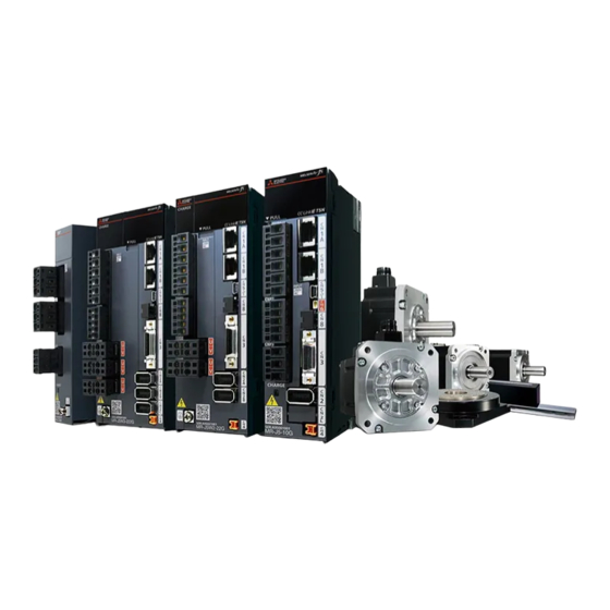
Mitsubishi Electric Melservo-J5 MR-J5 Series Manuals
Manuals and User Guides for Mitsubishi Electric Melservo-J5 MR-J5 Series. We have
4
Mitsubishi Electric Melservo-J5 MR-J5 Series manuals available for free PDF download: User Manual
Mitsubishi Electric Melservo-J5 MR-J5 Series User Manual (390 pages)
Brand:
Mitsubishi Electric
| Category:
Controller
| Size: 37.02 MB
Table of Contents
Safety Instructions
3
About the Manual
5
U.s. Customary Units
6
Table of Contents
7
Chapter 1 Function
12
Function Explanation
12
Chapter 2 Control Mode
19
Control Mode [G] [WG]
19
Control Switching
19
Cyclic Synchronous Position Mode (Csp)
20
Cyclic Synchronous Velocity Mode (Csv)
22
Cyclic Synchronous Torque Mode (Cst)
24
Profile Position Mode (Pp)
26
Profile Velocity Mode (Pv)
30
Profile Torque Mode (Tq)
34
Continuous Operation to Torque Control Mode (Ct)
37
Homing Mode (Hm) and Homing
42
Control Mode [A]
69
Control Switching
69
Position Control Mode (P)
69
Speed Control Mode (S)
73
Torque Control Mode (T)
75
Position/Speed Control Switching Mode (P/S)
78
Speed/Torque Control Switching Mode (S/T)
80
Torque/Position Control Switch Mode (T/P)
82
Chapter 3 Basic Function
83
Outline of Servo Parameter and Object Dictionary
83
Servo Parameter
83
Object Dictionary [G] [WG]
85
Rotation/Travel Direction Selection [G] [WG]
86
Setting Methods of Functions
87
Rotation/Travel Direction Selection [A]
90
Setting Methods of Functions
91
Stroke Limit Function [G] [WG]
92
Explanation of the Stroke Limit Signal Names
92
Setting Methods of Functions
93
Stop Method at Stroke Limit Detection
96
Servo Parameter List
97
Stroke Limit Function [A]
98
Setting Methods of Functions
98
Stop Method at Stroke Limit Detection
99
Servo Parameter List
99
Limit Switch Release Position Assessment Function [G] [WG]
100
Outline
100
Precautions
100
Setting Methods of Functions
100
Command Unit Select Function [G] [WG]
101
Speed Command Unit Selection Function [G] [WG]
101
Command Unit Select Function [A]
102
Torque Command Unit Selection Function
102
Electronic Gear Function [G] [WG]
103
Setting Method
103
Setting Example
104
Electronic Gear Function [A]
108
Setting Method
108
Setting Example
109
Electronic Gear Selection Function
111
In-Position Range Setting
112
Setting Method [G] [WG]
113
Setting Method [A]
113
Assigning I/O Devices
114
Setting Method [G] [WG]
115
Setting Method [A]
116
Regenerative Option Selection
117
Regenerative Option
117
Alarm Function
118
Operation Status at Alarm Occurrence [G] [WG]
118
Operation Status at Alarm Occurrence [A]
118
Operation Status at Warning Occurrence [G] [WG]
119
Operation Status at Warning Occurrence [A]
119
Returning from an Alarm [G] [WG]
120
Returning from an Alarm [A]
120
Returning from a Warning
120
Alarm History [G] [WG]
120
Alarm History [A]
122
Stop Method at Occurrence of Alarms/Warnings
122
Timing Chart at Alarm Occurrence
123
Forced Stop Deceleration Function
125
Setting Method [G] [WG]
125
Setting Method [A]
126
Timing Chart [G] [WG]
126
Timing Chart [A]
127
Electromagnetic Brake Interlock Function
128
Base Circuit Shut-Off Delay Time Function
128
Setting Method [G] [WG]
128
Setting Method [A]
129
Timing Chart
130
Vertical Axis Freefall Prevention Function
138
Setting Method [G] [WG]
138
Setting Method [A]
138
Timing Chart [G] [WG]
139
Timing Chart [A]
139
Acceleration/Deceleration Function
140
Acceleration/Deceleration Time Constant
140
S-Pattern Acceleration/Deceleration Time Constant [G] [WG]
142
S-Pattern Acceleration/Deceleration Time Constant [A]
143
Acceleration/Deceleration [G] [WG]
144
Quick Stop [G] [WG]
146
Objects for Setting
146
Timing Chart
147
Halt [G] [WG]
148
Objects for Setting
148
Timing Chart
148
Command Pulse Train Monitoring Function [A]
149
Setting a Command Frequency Error Threshold
149
Setting PEN (Command Input Permission Signal)
149
Chapter 4 Applicable Functions
150
Tough Drive Function
152
Vibration Tough Drive
152
Instantaneous Power Failure Tough Drive
152
Compliance with SEMI-F47 Standard
156
Setting Method
156
Behavior
156
Requirements of the SEMI-F47 Standard
156
Calculation Method of Tolerance against Instantaneous Power Failure
157
Scale Measurement Function [G] [WG]
158
Outline
158
Function Block Diagram
159
System Configuration
160
Scale Measurement Encoders
162
Setting Method
165
Related Objects
168
Touch Probe
169
Outline [G] [WG]
169
Setting Method [G] [WG]
170
Machine Diagnosis
179
Friction Vibration Estimation Function
180
Friction Failure Prediction Function
186
Vibration Failure Prediction Function
197
Total Travel Distance Failure Prediction Function
203
Gear Failure Diagnosis Function
210
Belt Diagnosis Function
217
Drive Recorder
236
Specification Outline
238
How to Use the Function [G] [WG]
238
How to Use the Function [A]
241
Servo Parameter/Object Dictionary
243
Standard Acquisition Waveform List [G] [WG]
256
Standard Acquisition Waveform List [A]
258
Waveform Recording Inapplicable Alarm List
260
List of Auxiliary Recording Data
261
Software Reset
262
Software Reset in MR Configurator2
262
Software Reset Via Network Communication [G] [WG]
262
Software Position Limit [G] [WG]
263
Setting Method
263
Torque Limit [G] [WG]
264
Setting Method
264
Checking "Limiting Torque" Status
266
Torque Limit [A]
267
Setting Method
268
Checking "Limiting Torque" Status
269
Speed Limit [G] [WG]
270
Setting Method
270
Checking "Limiting Speed" Status
270
Speed Limit [A]
271
Setting Method
271
Checking "Limiting Speed" Status
273
A/B/Z-Phase Pulse Output Function
274
Setting Method [G] [WG]
275
Setting Method [A]
278
Z-Phase Pulse Output
281
Infinite Feed Function [G] [WG]
282
Servo Amplifier Life Diagnosis Function
282
Cumulative Energization Time Function
282
Relay Usage Count Display Function
283
Encoder Communication Diagnosis Function
284
Usage [G] [WG]
284
Usage [A]
285
Diagnostic Procedure
285
Disconnection/Incorrect Wiring Detection Function
286
Input Open-Phase Detection Function
286
Output Open Phase Detection Function
288
Servo Motor Incorrect Wiring Detection Function [WG]
290
Overload Protection (Electronic Thermal) Function
292
Command Offset [G] [WG]
293
Chapter 5 Monitoring
295
Explanation of Monitor Signals
295
Name and Description of the Monitor Signals
295
Signal Block Diagram
307
Checking with MR Configurator2
310
Display All" Function
310
Graph Function
310
I/O Monitor Display
311
System Configuration Display
312
Analog Monitor [G] [WG]
313
Setting Method
313
Setting Details
314
Analog Monitor [A]
318
Setting Method
318
Setting Details
319
Functions and Configuration
323
Outline
323
Outline of Safety Sub-Functions
323
Risk Assessments
324
Chapter 6 Functional Safety
323
Signal
325
Explanation of Signals
325
Power-On Sequence
327
Setting Method
328
Setting Functional Safety Parameters
328
Functional Safety Parameters that Must be Set
329
Test Operation
330
Safety Sub-Function
331
Achievable Safety Level
331
I/O Function
333
STO Function
344
SS1 Function
347
SS2/SOS Function
354
SLS Function
360
SSM Function
364
SBC Function
365
SDI Function
366
SLI Function
369
SLT Function
371
Status Monitor (SM) Function
375
Multiple Operation Commands for Safety Sub-Functions
375
Simultaneous Operation of STO and SS1 Functions
376
At Alarm Occurrence
377
Troubleshooting
379
Parameter Combinations that Trigger [AL. 537.2 Parameter Combination Error a (Safety Sub-Function)]
379
Chapter 7 Network Function
381
IP Address Setting
381
Setting an IP Address [G] [WG]
381
Setting an IP Address [A]
381
Managing Accounts
381
Setting an Account
382
Precautions
382
FTP Server Function
383
Restrictions
383
Precautions
383
Directory Structure
384
Steps of Accessing the FTP Server
384
Firmware Update
385
Revisions
386
Warranty
387
Trademarks
388
Advertisement
Mitsubishi Electric Melservo-J5 MR-J5 Series User Manual (446 pages)
Brand:
Mitsubishi Electric
| Category:
Controller
| Size: 57.47 MB
Table of Contents
Safety Instructions
3
About the Manual
5
U.s. Customary Units
6
Table of Contents
7
Chapter 1 Introduction
14
Wiring Procedure
14
Servo Amplifier/Motor Combinations
15
Rotary Servo Motor
15
Linear Servo Motor
18
Direct Drive Motor
22
Wiring Check
24
Power Supply System Wiring
24
I/O Signal Wiring
26
Surrounding Environment
27
Chapter 2 Installation
28
Mounting Direction and Clearances
28
Keeping out Foreign Materials
31
Cable Stress
31
Fan Unit Replacement Procedure
31
List of Applicable Fan Units
31
Fan Unit Removal Procedure
32
Fan Unit Installation Procedure
33
Restrictions When Using this Product at an Altitude Exceeding 1000 M and up to 2000 M
33
Chapter 3 Signals and Wiring
34
Example Power Circuit Connections
35
200 V Class
36
Using Servo Amplifier with DC Power Supply Input
40
Example I/O Signal Connections
42
Mr-J5-_G
42
Mr-J5-_A
45
Mr-J5W_-_G
53
Explanation of Power Supply System
56
Explanation of Signals
56
Power-On Procedure [G] [WG]
58
Power-On Procedure [A]
59
Wiring CNP1, CNP2, and CNP3
60
Connectors and Pin Assignments
64
Precautions
64
Connectors and Pin Assignments [G]
65
Connectors and Pin Assignments [A]
66
Connectors and Pin Assignments [WG]
69
Signal (Device) Explanation
70
Input Device
70
Output Device
78
Input Signal
84
Output Signal
86
Power Supply
87
Interface
88
Internal Connection Diagram [G]
88
Internal Connection Diagram [A]
89
Internal Connection Diagram [WG]
92
Detailed Explanation of Interfaces
95
Source I/O Interface
99
Servo Motor with an Electromagnetic Brake
101
Connection Diagram [G] [A]
101
Grounding
103
Chapter 4 Dimensions
104
Mr-J5-_G
104
Mr-J5-10G_/Mr-J5-20G_/Mr-J5-40G
104
Mr-J5-60G
104
Mr-J5-70G_/Mr-J5-100G
105
Mr-J5-200G_/Mr-J5-350G
105
Mr-J5-500G
106
Mr-J5-700G
106
Mr-J5-_A
107
Mr-J5-10A_/Mr-J5-20A_/Mr-J5-40A
107
Mr-J5-60A
107
Mr-J5-70A_/Mr-J5-100A
108
Mr-J5-200A_/Mr-J5-350A
108
Mr-J5-500A
109
Mr-J5-700A
109
Mr-J5W_-_G
110
Mr-J5W2-22G_/Mr-J5W2-44G
110
Mr-J5W2-77G_/Mr-J5W2-1010G
110
Mr-J5W3-222G_/Mr-J5W3-444G
111
Connector
112
CN3 Connector [G]
112
CN3 Connector [A]
113
Cn3_Connector [WG]
114
SCR Connector System (3M)
115
Chapter 5 Characteristics
116
Overload Protection Characteristics
116
Power Supply Capacity and Generated Loss
119
Power Supply Capacity
119
Generated Loss
124
Using Servo Amplifier with DC Power Supply Input
125
Dynamic Brake Characteristics
126
Dynamic Brake Operation
127
Cable Flex Life
152
Inrush Currents at Power-On of Main Circuit and Control Circuit
153
Chapter 6 Options and Peripheral Equipment
154
Cable/Connector Sets
154
Combinations of Cable/Connector Sets
155
Ethernet Cable [G] [WG]
161
Regenerative Option
162
Combination and Regenerative Power
162
Selection of the Regenerative Option [G] [A]
163
Selection of the Regenerative Option [WG]
166
Servo Parameter Setting
170
Connection of Regenerative Option
170
Dimensions
171
MR-CM Simple Converter
175
Combination of Simple Converter and Servo Amplifier
175
Servo Amplifier Setting When Using a Simple Converter
175
Simple Converter Standard Specifications
175
External Interface
177
Signals and Wiring
180
Dimensions
182
Peripheral Equipment
183
Mounting Direction and Clearances
184
XC Multifunction Regeneration Converter
185
Precautions
185
Servo Amplifier Settings
185
Capacity Selection
185
Connection Diagram
188
Wiring and Peripheral Options
189
PS7DW-20V14B-F Junction Terminal Block (Recommended) [G]
192
MR-TB50 Junction Terminal Block [A]
194
MR-TB26A Junction Terminal Block [WG]
196
MR Configurator2
198
Engineering Tool
198
Precautions for Using USB Communication Function and Ethernet Communication Function
198
Selection Example of Wires
199
Molded-Case Circuit Breakers, Fuses, Magnetic Contactors
201
Main Circuit Wiring (Connecting Multiple Servo Amplifiers to One Molded-Case Circuit Breaker)
207
Example Settings that Comply with IEC/EN/UL 61800-5-1 and CSA C22.2 No.274
209
Power Factor Improving DC Reactor
211
Power Factor Improving AC Reactor
213
Relay (Recommended)
216
Noise Reduction Techniques
216
Earth-Leakage Current Breaker
225
Selection Method
225
Selection Example
228
EMC Filter (Recommended)
230
MR-J3-D05 Safety Logic Unit
235
Contents of the Package
235
Terms Related to Safety
235
Precautions
236
Residual Risks
236
Block Diagram and Timing Chart
237
Maintenance and Disposal
237
Functions and Configuration
238
Signal
241
Mitsubishi Electric Melservo-J5 MR-J5 Series User Manual (136 pages)
AC Servo System
Brand:
Mitsubishi Electric
| Category:
Controller
| Size: 10.69 MB
Table of Contents
Safety Instructions
3
About the Manual
5
U.s. Customary Units
5
Table of Contents
6
Chapter 1 Summary of Object Dictionary
18
Structure
18
Object Units
18
Using Appropriate Object Numbers
19
CHAPTER 2 General Objects
20
Device Type (Obj. 1000H)]
20
[Device Type (Obj. 1000H: 00H)]
20
Error Register (Obj. 1001H)]
20
[Error Register (Obj. 1001H: 00H)]
20
Manufacturer Device Name (Obj. 1008H)]
20
[Manufacturer Device Name (Obj. 1008H: 00H)]
20
Manufacturer Hardware Version (Obj. 1009H)]
21
[Manufacturer Hardware Version (Obj. 1009H: 00H)]
21
Manufacturer Software Version (Obj. 100Ah)]
21
[Manufacturer Software Version (Obj. 100Ah: 00H)]
21
Store Parameters (Obj. 1010H)]
21
[Store Parameters (Obj. 1010H: 00H)]
21
[Save All Parameters (Obj. 1010H: 01H)]
21
Restore Default Parameters (Obj. 1011H)]
22
[Restore Default Parameters (Obj. 1011H: 00H)]
22
[Restore All Default Parameters (Obj. 1011H: 01H)]
22
Identity Object (Obj. 1018H)]
23
[Identity Object (Obj. 1018H: 00H)]
23
[Vendor ID (Obj. 1018H: 01H)]
23
[Product Code (Obj. 1018H: 02H)]
23
[Revision Number (Obj. 1018H: 03H)]
23
[Serial Number (Obj. 1018H: 04H)]
23
Error Settings (Obj. 10F1H)]
24
[Error Settings (Obj. 10F1H: 00H)]
24
[Local Error Reaction (Obj. 10F1H: 01H)]
24
[Sync Error Counter Limit (Obj. 10F1H: 02H)]
24
Version Number (Obj. 67Feh)]
25
[Version Number (Obj. 67Feh: 00H)]
25
CHAPTER 3 PDO Mapping Objects
26
1St Receive PDO Mapping (Obj. 1600H)]
26
[1St Receive PDO Mapping (Obj. 1600H: 00H)]
26
[Mapped Object 001 (Obj. 1600H: 01H)] - [Mapped Object 032 (Obj. 1600H: 20H)]
27
2Nd Receive PDO Mapping (Obj. 1601H)]
28
[2Nd Receive PDO Mapping (Obj. 1601H: 00H)]
28
[Mapped Object 001 (Obj. 1601H: 01H)] - [Mapped Object 032 (Obj. 1601H: 20H)]
29
3Rd Receive PDO Mapping (Obj. 1602H)]
30
[3Rd Receive PDO Mapping (Obj. 1602H: 00H)]
30
4Th Receive PDO Mapping (Obj. 1603H)]
30
[4Th Receive PDO Mapping (Obj. 1603H: 00H)]
30
1St Transmit PDO Mapping (Obj. 1A00H)]
30
[1St Transmit PDO Mapping (Obj. 1A00H: 00H)]
30
[Mapped Object 001 (Obj. 1A00H: 01H)] - [Mapped Object 032 (Obj. 1A00H: 20H)]
31
2Nd Transmit PDO Mapping (Obj. 1A01H)]
32
[2Nd Transmit PDO Mapping (Obj. 1A01H: 00H)]
32
[Mapped Object 001 (Obj. 1A01H: 01H)] - [Mapped Object 032 (Obj. 1A01H: 20H)]
33
3Rd Transmit PDO Mapping (Obj. 1A02H)]
34
[3Rd Transmit PDO Mapping (Obj. 1A02H: 00H)]
34
4Th Transmit PDO Mapping (Obj. 1A03H)]
34
[4Th Transmit PDO Mapping (Obj. 1A03H: 00H)]
34
CHAPTER 4 Sync Manager Communication Objects
35
Sync Manager Communication Type (Obj. 1C00H)]
35
[Sync Manager Communication Type (Obj. 1C00H: 00H)]
35
[Sync Manager 0 (Obj. 1C00H: 01H)]
35
[Sync Manager 1 (Obj. 1C00H: 02H)]
35
[Sync Manager 2 (Obj. 1C00H: 03H)]
35
[Sync Manager 3 (Obj. 1C00H: 04H)]
35
Sync Manager Rxpdo Assign (Obj. 1C12H)]
36
[Sync Manager Rxpdo Assign (Obj. 1C12H: 00H)]
36
[Assigned PDO 001 (Obj. 1C12H: 01H)]
36
[Assigned PDO 002 (Obj. 1C12H: 02H)]
36
[Assigned PDO 003 (Obj. 1C12H: 03H)]
36
[Assigned PDO 004 (Obj. 1C12H: 04H)]
36
Sync Manager Txpdo Assign (Obj. 1C13H)]
37
[Sync Manager Txpdo Assign (Obj. 1C13H: 00H)]
37
[Assigned PDO 001 (Obj. 1C13H: 01H)]
37
[Assigned PDO 002 (Obj. 1C13H: 02H)]
37
[Assigned PDO 003 (Obj. 1C13H: 03H)]
37
[Assigned PDO 004 (Obj. 1C13H: 04H)]
37
SM Output Parameter (Obj. 1C32H)]
38
[SM Output Parameter (Obj. 1C32H: 00H)]
38
[Synchronization Type (Obj. 1C32H: 01H)]
38
[Cycle Time (Obj. 1C32H: 02H)]
38
[Synchronization Types Supported (Obj. 1C32H: 04H)]
39
[Minimum Cycle Time (Obj. 1C32H: 05H)]
39
[Calc and Copy Time (Obj. 1C32H: 06H)]
39
[Delay Time (Obj. 1C32H: 09H)]
40
[Cycle Time too Small (Obj. 1C32H: 0Ch)]
40
SM Input Parameter (Obj. 1C33H)]
40
[SM Input Parameter (Obj. 1C33H: 00H)]
40
[Synchronization Type (Obj. 1C33H: 01H)]
40
[Cycle Time (Obj. 1C33H: 02H)]
41
[Synchronization Types Supported (Obj. 1C33H: 04H)]
41
[Minimum Cycle Time (Obj. 1C33H: 05H)]
42
[Calc and Copy Time (Obj. 1C33H: 06H)]
42
[Delay Time (Obj. 1C33H: 09H)]
42
[Cycle Time too Small (Obj. 1C33H: 0Ch)]
42
CHAPTER 5 Parameter Objects
43
PA01 (Obj. 2001H)] - [PA44 (Obj. 202Ch)]
43
PB01 (Obj. 2081H)] - [PB92 (Obj. 20Dch)]
43
PC01 (Obj. 2101H)] - [PC90 (Obj. 215Ah)]
43
PD01 (Obj. 2181H)] - [PD72 (Obj. 21C8H)]
43
PE01 (Obj. 2201H)] - [PE88 (Obj. 2258H)]
43
PF01 (Obj. 2281H)] - [PF99 (Obj. 22E3H)]
43
PL01 (Obj. 2401H)] - [PL72 (Obj. 2448H)]
43
PT01 (Obj. 2481H)] - [PT90 (Obj. 24Dah)]
43
PN01 (Obj. 2581H)] - [PN32 (Obj. 25A0H)]
43
PV Group Parameters (Obj. 2691H)]
44
[PV Group Parameters (Obj. 2691H: 00H)]
44
[PV01 (Obj. 2691H: 01H)] - [PV32 (Obj. 2691H: 20H)]
44
CHAPTER 6 Alarm Objects
45
Alarm History Newest (Obj. 2A00H)]
45
[Alarm History Newest (Obj. 2A00H: 00H)]
45
[Alarm No. (Obj. 2A00H: 01H)]
45
[Alarm Time (Hour) (Obj. 2A00H: 02H)]
45
[Alarm2 No. (Obj. 2A00H: 03H)]
45
[Alarm Time (Second) (Obj. 2A00H: 04H)]
46
[Alarm Time (Nanosecond) (Obj. 2A00H: 05H)]
46
[Alarm Time (Time Zone) (Obj. 2A00H: 06H)]
46
[Alarm Time (Summer Time) (Obj. 2A00H: 07H)]
46
Alarm History _1 (Obj. 2A01H)] - [Alarm History _15 (Obj. 2A0Fh)]
47
Clear Alarm History (Obj. 2A40H)]
47
[Clear Alarm History (Obj. 2A40H: 00H)]
47
Current Alarm (Obj. 2A41H)]
47
[Current Alarm (Obj. 2A41H: 00H)]
47
Parameter Error Number (Obj. 2A44H)]
47
[Parameter Error Number (Obj. 2A44H: 00H)]
47
Parameter Error List (Obj. 2A45H)]
48
[Parameter Error List (Obj. 2A45H: 00H)]
48
[Parameter Error List 1 (Obj. 2A45H: 01H)] - [Parameter Error List 254 (Obj. 2A45H: Feh)]
48
Reset Alarm (Obj. 2A46H)]
49
[Reset Alarm (Obj. 2A46H: 00H)]
49
Drive Recorder History Newest (Obj. 2A70H)]
49
[Drive Recorder History Newest (Obj. 2A70H: 00H)]
49
[Drive Recorder History Index (Obj. 2A70H: 01H)]
49
[Drive Recorder History Alarm Number (Obj. 2A70H: 02H)]
49
[Drive Recorder History Power on Time (Obj. 2A70H: 03H)]
50
[Drive Recorder History Time (Second) (Obj. 2A70H: 04H)]
50
[Drive Recorder History Time (Nanosecond) (Obj. 2A70H: 05H)]
50
[Drive Recorder History (Time Zone) (Obj. 2A70H: 06H)]
50
[Drive Recorder History (Summer Time) (Obj. 2A70H: 07H)]
50
Drive Recorder History_1 (Obj. 2A71H)] - [Drive Recorder History_15 (Obj. 2A7Fh)]
51
CHAPTER 7 Monitor Objects
52
Cumulative Feedback Pulses (Obj. 2B01H)]
52
[Cumulative Feedback Pulses (Obj. 2B01H: 00H)]
52
[Number of Tough Drive Operations (Obj. 2B28H: 00H)]
58
Internal Temperature of Amplifier (Obj. 2B2Ah)]
58
[Internal Temperature of Amplifier (Obj. 2B2Ah: 00H)]
58
Unit Power Consumption (Obj. 2B2Dh)]
58
[Unit Power Consumption (Obj. 2B2Dh: 00H)]
58
Unit Total Power Consumption (Obj. 2B2Eh)]
58
[Unit Total Power Consumption (Obj. 2B2Eh: 00H)]
58
Error Excessive Alarm Margin (Obj. 2B3Fh)]
59
[Error Excessive Alarm Margin (Obj. 2B3Fh: 00H)]
59
Overload Alarm Margin (Obj. 2B40H)]
59
[Overload Alarm Margin (Obj. 2B40H: 00H)]
59
Overshoot Amount (Obj. 2B41H)]
59
[Overshoot Amount (Obj. 2B41H: 00H)]
59
Torque/Thrust Equivalent to Disturbance (Obj. 2B42H)]
59
[Torque/Thrust Equivalent to Disturbance (Obj. 2B42H: 00H)]
59
Unit Power Consumption 2 (Obj. 2B43H)]
60
[Unit Power Consumption 2 (Obj. 2B43H: 00H)]
60
CHAPTER 8 Manufacturer Specific Control Object
61
Drive Recorder Status (Obj. 2C02H)]
61
[Drive Recorder Status (Obj. 2C02H: 00H)]
61
Clear Drive Recorder History (Obj. 2C03H)]
61
[Clear Drive Recorder History (Obj. 2C03H: 00H)]
61
Power on Cumulative Time (Obj. 2C18H)]
61
[Power on Cumulative Time (Obj. 2C18H: 00H)]
61
Number of Inrush Relay On/Off Times (Obj. 2C19H)]
61
[Number of Inrush Relay On/Off Times (Obj. 2C19H: 00H)]
61
Dynamic Relay ON/OFF Number (Obj. 2C1Ah)]
62
[Dynamic Relay ON/OFF Number (Obj. 2C1Ah: 00H)]
62
Machine Diagnostic Status (Obj. 2C20H)]
62
[Machine Diagnostic Status (Obj. 2C20H: 00H)]
62
Static Friction Torque at Forward Rotation (Obj. 2C21H)]
63
[Static Friction Torque at Forward Rotation (Obj. 2C21H: 00H)]
63
Dynamic Friction Torque at Forward Rotation (at Rated Speed) (Obj. 2C22H)]
63
[Dynamic Friction Torque at Forward Rotation (at Rated Speed) (Obj. 2C22H: 00H)]
63
Static Friction Torque at Reverse Rotation (Obj. 2C23H)]
63
[Static Friction Torque at Reverse Rotation (Obj. 2C23H: 00H)]
63
Dynamic Friction Torque at Reverse Rotation (at Rated Speed) (Obj. 2C24H)]
63
[Dynamic Friction Torque at Reverse Rotation (at Rated Speed) (Obj. 2C24H: 00H)]
63
Oscillation Frequency During Motor Stop (Obj. 2C25H)]
64
[Oscillation Frequency During Motor Stop (Obj. 2C25H: 00H)]
64
Vibration Level During Motor Stop (Obj. 2C26H)]
64
[Oscillation Frequency During Motor Stop (Obj. 2C26H: 00H)]
64
Oscillation Frequency During Motor Operating (Obj. 2C27H)]
64
[Oscillation Frequency During Motor Operating (Obj. 2C27H: 00H)]
64
Vibration Level During Motor Operating (Obj. 2C28H)]
64
[Vibration Level During Motor Operating (Obj. 2C28H: 00H)]
64
Fault Prediction Status (Obj. 2C29H)]
65
[Fault Prediction Status (Obj. 2C29H: 00H)]
65
Friction Based Fault Prediction Upper Threshold (Obj. 2C2Ah)]
66
[Encoder Status 1 (Obj. 2D35H: 01H)]
81
[Encoder Status 2 (Obj. 2D35H: 02H)]
81
Scale Cycle Counter (Obj. 2D36H)]
82
[Scale Cycle Counter (Obj. 2D36H: 00H)]
82
Scale ABS Counter (Obj. 2D37H)]
82
[Scale ABS Counter (Obj. 2D37H: 00H)]
82
Scale Measurement Encoder Resolution (Obj. 2D38H)]
83
[Scale Measurement Encoder Resolution (Obj. 2D38H: 00H)]
83
Scale Measurement Encoder Reception Status (Obj. 2D3Ch)]
83
[Scale Measurement Encoder Reception Status (Obj. 2D3Ch: 00H)]
83
Servo Motor Serial Number (Obj. 2D46H)]
83
[Servo Motor Serial Number (Obj. 2D46H: 00H)]
83
Motor Data 2 (Obj. 2D48H)]
84
[Motor Data 2 (Obj. 2D48H: 00H)]
84
[Motor ID 1 (Obj. 2D48H: 01H)]
84
[Motor ID 2 (Obj. 2D48H: 02H)]
84
[Encoder ID 1 (Obj. 2D48H: 03H)]
84
[Encoder ID 2 (Obj. 2D48H: 04H)]
85
One-Touch Tuning Mode (Obj. 2D50H)]
85
[One-Touch Tuning Mode (Obj. 2D50H: 00H)]
85
One-Touch Tuning Status (Obj. 2D51H)]
85
[One-Touch Tuning Status (Obj. 2D51H: 00H)]
85
One-Touch Tuning Stop (Obj. 2D52H)]
85
[One-Touch Tuning Stop (Obj. 2D52H: 00H)]
85
One-Touch Tuning Clear (Obj. 2D53H)]
86
[One-Touch Tuning Clear (Obj. 2D53H: 00H)]
86
One-Touch Tuning Error Code (Obj. 2D54H)]
86
[One-Touch Tuning Error Code (Obj. 2D54H: 00H)]
86
CHAPTER 9 PDS Control Objects
87
Error Code (Obj. 603Fh)]
87
[Error Code (Obj. 603Fh: 00H)]
87
Controlword (Obj. 6040H)]
87
[Controlword (Obj. 6040H: 00H)]
87
Statusword (Obj. 6041H)]
89
[Statusword (Obj. 6041H: 00H)]
89
Quick Stop Option Code (Obj. 605Ah)]
91
[Quick Stop Option Code (Obj. 605Ah: 00H)]
91
Halt Option Code (Obj. 605Dh)]
92
[Halt Option Code (Obj. 605Dh: 00H)]
92
Modes of Operation (Obj. 6060H)]
93
[Modes of Operation (Obj. 6060H: 00H)]
93
Modes of Operation Display (Obj. 6061H)]
93
[Modes of Operation Display (Obj. 6061H: 00H)]
93
Supported Drive Modes (Obj. 6502H)]
94
[Supported Drive Modes (Obj. 6502H: 00H)]
94
CHAPTER 10 Position Control Function Objects
95
Position Actual Internal Value (Obj. 6063H)]
95
[Position Actual Internal Value (Obj. 6063H: 00H)]
95
Position Actual Value (Obj. 6064H)]
95
[Position Actual Value (Obj. 6064H: 00H)]
95
Following Error Window (Obj. 6065H)]
95
[Following Error Window (Obj. 6065H: 00H)]
95
Following Error Time out (Obj. 6066H)]
95
[Following Error Time out (Obj. 6066H: 00H)]
95
Position Window (Obj. 6067H)]
96
[Position Window (Obj. 6067H: 00H)]
96
Position Window Time (Obj. 6068H)]
96
[Position Window Time (Obj. 6068H: 00H)]
96
Positioning Option Code (Obj. 60F2H)]
96
[Positioning Option Code (Obj. 60F2H: 00H)]
96
Following Error Actual Value (Obj. 60F4H)]
97
[Following Error Actual Value (Obj. 60F4H: 00H)]
97
Control Effort (Obj. 60Fah)]
97
[Control Effort (Obj. 60Fah: 00H)]
97
CHAPTER 11 Profile Velocity Mode Objects
98
Velocity Demand Value (Obj. 606Bh)]
98
[Velocity Demand Value (Obj. 606Bh: 00H)]
98
Velocity Actual Value (Obj. 606Ch)]
98
[Velocity Actual Value (Obj. 606Ch: 00H)]
98
Velocity Window (Obj. 606Dh)]
99
[Velocity Window (Obj. 606Dh: 00H)]
99
Velocity Window Time (Obj. 606Eh)]
99
[Velocity Window Time (Obj. 606Eh: 00H)]
99
Velocity Threshold (Obj. 606Fh)]
99
[Velocity Threshold (Obj. 606Fh: 00H)]
99
Velocity Threshold Time (Obj. 6070H)]
100
[Velocity Threshold Time (Obj. 6070H: 00H)]
100
Target Velocity (Obj. 60Ffh)]
100
[Target Velocity (Obj. 60Ffh: 00H)]
100
CHAPTER 12 Profile Torque Mode Objects
101
Positive/Negative Torque Limit 2 (Obj. 2D6Dh)]
101
[Positive/Negative Torque Limit 2 Setting (Obj. 2D6Dh: 00H)]
101
[Positive/Negative Torque Limit 2 Select (Obj. 2D6Dh: 01H)]
101
[Positive Torque Limit Value 2 (Obj. 2D6Dh: 02H)]
101
[Negative Torque Limit Value 2 (Obj. 2D6Dh: 03H)]
102
Target Torque (Obj. 6071H)]
102
[Target Torque (Obj. 6071H: 00H)]
102
Max Torque (Obj. 6072H)]
102
[Max Torque (Obj. 6072H: 00H)]
102
Torque Demand Value (Obj. 6074H)]
102
[Torque Demand Value (Obj. 6074H: 00H)]
102
Torque Actual Value (Obj. 6077H)]
103
[Torque Actual Value (Obj. 6077H: 00H)]
103
Torque Slope (Obj. 6087H)]
103
[Torque Slope (Obj. 6087H: 00H)]
103
Torque Profile Type (Obj. 6088H)]
103
[Torque Profile Type (Obj. 6088H: 00H)]
103
Positive Torque Limit Value (Obj. 60E0H)]
103
[Positive Torque Limit Value (Obj. 60E0H: 00H)]
103
Negative Torque Limit Value (Obj. 60E1H)]
104
[Negative Torque Limit Value (Obj. 60E1H: 00H)]
104
CHAPTER 13 Profile Position Mode Objects
105
Target Position (Obj. 607Ah)]
105
[Target Position (Obj. 607Ah: 00H)]
105
Position Range Limit (Obj. 607Bh)]
105
[Position Range Limit (Obj. 607Bh: 00H)]
105
[Min Position Range Limit (Obj. 607Bh: 01H)]
105
[Max Position Range Limit (Obj. 607Bh: 02H)]
105
Software Position Limit (Obj. 607Dh)]
106
[Software Position Limit (Obj. 607Dh: 00H)]
106
[Min Position Limit (Obj. 607Dh: 01H)]
106
[Max Position Limit (Obj. 607Dh: 02H)]
106
Max Profile Velocity (Obj. 607Fh)]
107
[Max Profile Velocity (Obj. 607Fh: 00H)]
107
Max Motor Speed (Obj. 6080H)]
107
[Max Motor Speed (Obj. 6080H: 00H)]
107
Profile Velocity (Obj. 6081H)]
108
[Profile Velocity (Obj. 6081H: 00H)]
108
Profile Acceleration (Obj. 6083H)]
108
[Profile Acceleration (Obj. 6083H: 00H)]
108
Profile Deceleration (Obj. 6084H)]
109
[Profile Deceleration (Obj. 6084H: 00H)]
109
Quick Stop Deceleration (Obj. 6085H)]
109
[Quick Stop Deceleration (Obj. 6085H: 00H)]
109
Motion Profile Type (Obj. 6086H)]
110
[Motion Profile Type (Obj. 6086H: 00H)]
110
CHAPTER 14 Homing Mode Objects
111
Home Offset (Obj. 607Ch)]
111
[Home Offset (Obj. 607Ch: 00H)]
111
Homing Method (Obj. 6098H)]
111
[Homing Method (Obj. 6098H: 00H)]
111
Homing Speeds (Obj. 6099H)]
111
[Homing Speeds (Obj. 6099H: 00H)]
111
[Speed During Search for Switch (Obj. 6099H: 01H)]
111
[Speed During Search for Zero (Obj. 6099H: 02H)]
112
Homing Acceleration (Obj. 609Ah)]
112
[Homing Acceleration (Obj. 609Ah: 00H)]
112
Supported Homing Method (Obj. 60E3H)]
112
[Supported Homing Method (Obj. 60E3H: 00H)]
112
[1St Supported Homing Method (Obj. 60E3H: 01H)] - [41St Supported Homing Method (Obj. 60E3H: 29H)]
113
CHAPTER 15 Factor Group Objects
114
Polarity (Obj. 607Eh)]
114
[Polarity (Obj. 607Eh: 00H)]
114
Position Encoder Resolution (Obj. 608Fh)]
115
[Position Encoder Resolution (Obj. 608Fh: 00H)]
115
[Encoder Increments (Obj. 608Fh: 01H)]
115
[Motor Revolutions (Obj. 608Fh: 02H)]
115
Gear Ratio (Obj. 6091H)]
116
[Gear Ratio (Obj. 6091H: 00H)]
116
[Motor Revolutions (Obj. 6091H: 01H)]
116
[Shaft Revolutions (Obj. 6091H: 02H)]
116
Feed Constant (Obj. 6092H)]
117
[Feed Constant (Obj. 6092H: 00H)]
117
[Feed (Obj. 6092H: 01H)]
117
[Shaft Revolutions (Obj. 6092H: 02H)]
117
Unit Position (Obj. 60A8H)]
118
[SI Unit Position (Obj. 60A8H: 00H)]
118
Unit Velocity (Obj. 60A9H)]
118
[SI Unit Velocity (Obj. 60A9H: 00H)]
118
Unit Acceleration (Obj. 60Aah)]
118
[SI Unit Acceleration (Obj. 60Aah: 00H)]
118
CHAPTER 16 Touch Probe Function Objects
119
Touch Probe Function 2 (Obj. 2De8H)]
119
[Touch Probe Function 2 (Obj. 2De8H: 00H)]
119
Touch Probe Status 2 (Obj. 2De9H)]
120
[Touch Probe Status 2 (Obj. 2De9H: 00H)]
120
Touch Probe 3 Positive Edge (Obj. 2Deah)]
120
[Touch Probe 3 Positive Edge (Obj. 2Deah: 00H)]
120
Touch Probe 3 Negative Edge (Obj. 2Debh)]
120
[Touch Probe 3 Negative Edge (Obj. 2Debh: 00H)]
120
Touch Probe Function (Obj. 60B8H)]
121
[Touch Probe Function (Obj. 60B8H: 00H)]
121
Touch Probe Status (Obj. 60B9H)]
122
[Touch Probe Status (Obj. 60B9H: 00H)]
122
Touch Probe 1 Positive Edge (Obj. 60Bah)]
123
[Touch Probe 1 Positive Edge (Obj. 60Bah: 00H)]
123
Touch Probe 1 Negative Edge (Obj. 60Bbh)]
123
[Touch Probe 1 Negative Edge (Obj. 60Bbh: 00H)]
123
Touch Probe 2 Positive Edge (Obj. 60Bch)]
123
[Touch Probe 2 Positive Edge (Obj. 60Bch: 00H)]
123
Touch Probe 2 Negative Edge (Obj. 60Bdh)]
123
[Touch Probe 2 Negative Edge (Obj. 60Bdh: 00H)]
123
CHAPTER 17 Optional Application FE Objects
124
Digital Inputs (Obj. 60Fdh)]
124
[Digital Inputs (Obj. 60Fdh: 00H)]
124
CHAPTER 18 Cyclic Synchronous Position Mode Objects
130
Position Offset (Obj. 60B0H)]
130
[Position Offset (Obj. 60B0H: 00H)]
130
Velocity Offset (Obj. 60B1H)]
130
[Velocity Offset (Obj. 60B1H: 00H)]
130
Torque Offset (Obj. 60B2H)]
130
[Torque Offset (Obj. 60B2H: 00H)]
130
Revisions
132
Warranty
133
Trademarks
134
Advertisement
Mitsubishi Electric Melservo-J5 MR-J5 Series User Manual (116 pages)
Troubleshooting
Brand:
Mitsubishi Electric
| Category:
Amplifier
| Size: 8.76 MB
Table of Contents
About the Manual
3
U.s. Customary Units
3
Table of Contents
4
Chapter 1 Servo Amplifier Troubleshooting
7
Outline
7
The List of Alarm No./Warning no
9
Explanation of the Lists
9
Handling Methods for Alarms/Warnings
15
[AL. 010_Undervoltage]
15
[AL. 011_Switch Setting Error]
16
[AL. 012_Memory Error 1 (RAM)]
17
[AL. 013_Clock Error]
18
[AL. 014_Control Process Error]
19
[AL. 016_Encoder Initial Communication Error 1]
20
[AL. 017_Board Error]
22
[AL. 019_Memory Error 3]
24
[AL. 01A_Servo Motor Combination Error]
25
[AL. 01E_Encoder Initial Communication Error 2]
26
[AL. 01F_Encoder Initial Communication Error 3]
27
[AL. 020_Encoder Normal Communication Error 1]
28
[AL. 021_Encoder Normal Communication Error 2]
30
[AL. 024_Main Circuit Error]
31
[AL. 025_Absolute Position Erased]
32
[AL. 027_Initial Magnetic Pole Detection Error]
33
[AL. 028_Linear Encoder Error 2]
35
[AL. 02A_Linear Encoder Error 1]
36
[AL. 02B_Encoder Counter Error]
37
[AL. 030_Regenerative Error]
38
[AL. 031_Overspeed]
39
[AL. 032_Overcurrent]
40
[AL. 033_Overvoltage]
41
[AL. 035_Command Frequency Error]
42
[AL. 037_Parameter Error]
43
[AL. 03A_Inrush Current Suppression Circuit Error]
44
[AL. 042_Servo Control Error]
45
[AL. 045_Main Circuit Device Overheat]
47
[AL. 046_Servo Motor Overheat]
48
[AL. 047_Cooling Fan Error]
49
[AL. 050_Overload 1]
50
[AL. 051_Overload 2]
52
[AL. 052_Excessive Error]
53
[AL. 054_Oscillation Detection]
55
[AL. 056_Forced Stop Error]
56
[AL. 063_STO Timing Error]
57
[AL. 068_STO Diagnosis Error]
58
[AL. 069_Command Error]
59
[AL. 086_Network Communication Error]
61
[AL. 088_Watchdog 1]/[AL. 888_Watchdog 1]/[AL. 88888_Watchdog 1]
62
[AL. 08E_Serial Communication Error]
63
[AL. 090_Homing Incomplete Warning]
64
[AL. 091_Servo Amplifier Overheat Warning]
65
[AL. 092_Battery Cable Disconnection Warning]
66
[AL. 093_ABS Data Transfer Warning]
67
[AL. 095_STO Warning]
68
[AL. 096_Home Position Setting Warning]
69
[AL. 098_Software Position Limit Warning]
70
[AL. 099_Stroke Limit Warning]
71
[AL. 09B_Excessive Error Warning]
72
[AL. 09E_Network Warning]
73
[AL. 09F_Battery Warning]
74
[AL. 0E0_Excessive Regenerative Error]
75
[AL. 0E1_Overload Warning 1]
76
[AL. 0E2_Servo Motor Overheat Warning]
78
[AL. 0E3_Absolute Position Counter Warning]
79
[AL. 0E5_ABS Time-Out Warning]
80
[AL. 0E6_Servo Forced Stop Warning]
81
[AL. 0E8_Cooling Fan Speed Reduction Warning]
82
[AL. 0E9_Main Circuit off Warning]
83
[AL. 0EA_ABS Servo-On Warning]
84
[AL. 0Eb_The Other Axis Error Warning]
85
[AL. 0Ec_Overload Warning 2]
86
[AL. 0Ed_Output Watt Excess Warning]
87
[AL. 0F0_Tough Drive Warning]
88
[AL. 0F2_Drive Recorder Warning]
89
[AL. 0F3_Oscillation Detection Warning]
90
[AL. 0F7_Machine Diagnosis Warning]
91
[AL. 118_Encoder Diagnosis]
93
[AL. 119_Memory Error 4]
94
[AL. 11A_Servo Motor Constant Error]
95
[AL. 130_Regenerative Error 2]
96
[AL. 139_Open Phase Error]
97
[AL. 168_STO Function Error]
98
[AL. 188_Watchdog 2]
99
[AL. 1E9_Open Phase Warning]
100
[AL. 1F8_Memory Warning 1]
101
Trouble Which Does Not Trigger an Alarm/Warning
102
The Display Shows "A" (Unconnected to the Controller)
102
The Display Shows "R
102
The Display Shows "TST
102
The Display Shows "Off
103
The Display Is Turned off
103
The Servo Motor Does Not Operate
103
The Increase in the Servo Motor Speed Is Insufficient or Excessive
104
The Servo Motor Vibrates with Low Frequency
105
An Unusual Noise Is Occurring in the Servo Motor
105
The Servo Motor Vibrates
106
Poor Speed Accuracy (Unstable Speed of Servo Motor)
106
The Machine Vibrates Unsteadily When It Stops
107
Overshoot/Undershoot Occurs
107
The Servo Motor Starts Moving Immediately after the Power-On of the Servo Amplifier or Servo-On
107
The Home Position Deviates at the Homing
108
The Position Deviates During Operation after the Homing
108
In the Absolute Position Detection System, a Position Mismatch Occurs at Power Restoration
109
Communication with the Servo Amplifier Fails Using MR Configurator2
109
Electromagnetic Brake Went out
109
Electromagnetic Brake Cannot be Released
109
Coasting Distance of the Servo Motor Became Longer
110
Revisions
112
Warranty
113
Trademarks
114
Advertisement
Related Products
Mitsubishi Electric MELSERVO-J5 MR-J5-G Series
Mitsubishi Electric MELSERVO-J5 MR-J5-G-N1
Mitsubishi Electric Melservo-J3 Series MR-J3-B
Mitsubishi Electric MELSERVO-J2M series
Mitsubishi Electric MELSERVO-J2 Series
Mitsubishi Electric MELSERVO-J4 MR-J4-11KTM
Mitsubishi Electric MELSERVO-J4 MR-J4-22KTM
Mitsubishi Electric MELSERVO-J4 MR-J4-22KTM4
Mitsubishi Electric MELSERVO-J5 TM-RFM002C20
Mitsubishi Electric MELSERVO-J5 TM-RFM006C20
Mitsubishi Electric Categories
Air Conditioner
Controller
Projector
Inverter
Heat Pump
More Mitsubishi Electric Manuals
Login
Sign In
OR
Sign in with Facebook
Sign in with Google
Upload manual
Upload from disk
Upload from URL