Sign In
Upload
Manuals
Brands
MEP Manuals
Saw
SHARK 282
MEP SHARK 282 Manuals
Manuals and User Guides for MEP SHARK 282. We have
1
MEP SHARK 282 manual available for free PDF download: Use And Maintenance Manual
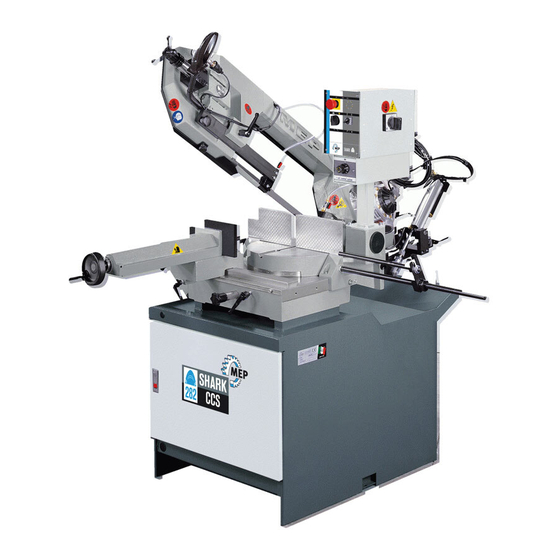
MEP SHARK 282 Use And Maintenance Manual (152 pages)
manual pulldown bandsaw machine
Brand:
MEP
| Category:
Saw
| Size: 6.51 MB
Table of Contents
Table of Contents
5
Introduction and Technical Specifications
9
Foreword
9
Machine Presentation
10
Machine Specification
10
Name Plate
10
Dimensions 1
11
Dimensions
14
Functional Parts
15
SHARK 282 Model
15
Cutting Head
16
Vice
16
Control Panel
17
Turntable
17
Base
18
Safety and Accident Prevention
19
Use of the Machine
19
General Recommendations
20
Recommendations to the Operator
21
Machine Safety Devices
23
Reference Standards
23
Protection against Accidental Contact with the Blade
24
Electrical Equipment
24
Emergency Devices
25
Noise Level of the Machine
26
Noise Level Measurement
26
Noise Level Values
26
Vibration Emission
27
Electromagnetic Compatibility
27
Machine Installation
29
Packaging and Storage
29
Anchoring the Machine
32
Minimum Requirements
32
Check List
33
Balancing the Cutting Head
34
Connection to the Compressed
34
Connection to the Power Supply
35
Description of Machine Operation
37
Description of the Control Panel
37
Basic Instructions for Carrying out a Cutting Operation Cycle
40
Manoeuvring the Cutting Head
40
Clamping the Work Piece in the Vice
41
Clamping the Work Piece in the Automatic Vice (MA Version)
41
Rapid Vice Positioning
42
Rapid Translation of the Vice
42
Width of Cut
43
Preliminary Check List for Cutting Operation
44
Manual Operating Cycle
44
CCS (Cut Control System) Functioning Cycle
47
Angled Cuts
49
Angled Cuts 45° to the Left
49
Angled Cuts 60° to the Left
50
Angled Cuts 45° to the Right
52
Diagrams, Exploded Views and Replacement Parts
53
Pneumatic Diagram (MA Version)
53
How to Read the Wiring Diagrams
54
Standardised Wiring Diagrams (CENELEC Standard)
59
Exploded Views 6
61
Exploded Views
74
Motor Assembly
74
Front Flywheel Assembly
76
Motor Flywheel Assembly
78
Cutting Head Cover
80
Vice Assembly
82
Base Assembly
84
Control Panel
86
Handgrip
88
Fixed Work Table and Turntable
90
Optional Cut Control System
92
Supplementary Pneumatic Vice
94
Adjustments
97
Air Treatment Unit (MA Version)
97
Topping up and Bleeding the Cylinder (Cut Control System Optional)
98
Topping up the Head Cylinder
98
Bleeding the Head Cylinder
99
Vice
100
Vice Play Adjustment
100
Cutting Head
101
Blade Tensioner Slide Play Adjustment
101
Blade Tensioning Unit
102
Adjusting Operating Head Travel
104
Blade Guide Parts
105
Blade Guide Heads
105
Blade Steady Buttons
105
Blade Guide Plates
105
Blade
108
Tool Change
108
Blade Perpendicularity
110
Orthogonality of the Blade
111
Front Flywheel
115
Motor Flywheel
116
Maintenance and Choice of Consumables
117
The Role of the Operator
117
Maintenance Requirements
118
General Maintenance
118
Daily
118
Weekly
118
Monthly
119
Maintenance of Working Parts
119
Consumable Materials
119
Oil for Blade Tensioner Cylinder
119
Oils for Cut Control System Hydraulic Circuit
120
Oil for Transmission Box
120
Oil for Lubricant/Coolant Fluid
120
Oils for Spray Mist System (Optional)
120
Cutting Speed and Choice of Tools
121
Cutting Speed
121
Standard Machine
121
Machine with 4/8 Pole Motor (Optional)
121
Machine with Inverter (Optional)
122
Choice of Blade
123
Saw Tooth Pitch
123
Cutting Speed and Downstroke Speed
124
Types of Swarf
124
Lubricant/Coolant Fluid
125
Blade Structure
126
Blade Types
126
Conventional Rake
127
Positive Rake
127
Variable Pitch
127
Variable Pitch Blades with 0° Cutting Angle
128
Variable Pitch with Positive Rake (from 9 to 10 Degrees)
128
Set
128
Standard or Splayed Set
128
Undulated Set
129
Alternating Grouped Sets
129
Alternating Set
129
Blade Selection Table Relating to Cutting Speed and Downstroke Speed
130
Classification of Steels
131
Classification of Steels 9
132
Troubleshooting
133
Troubleshooting Blade and Cutting Problems
133
Troubleshooting Machine Faults
140
Accessory Installation
143
Automatic Vice Kit
143
Blade
144
Cut Control System
144
Electronic Rpm Variator (Inverter)
145
Rod Marked off in Millimetres
147
Roller Table
148
Support for the Roller Platform on the Feeding/Discharging Side
149
Discharge Side Roller Table Adaptoradattatore Pianale a Rulli Lato Scarico
150
Advertisement
Advertisement
Related Products
MEP PH 100
MEP PH160
MEP Categories
Saw
Engine
Safes
Industrial Equipment
More MEP Manuals
Login
Sign In
OR
Sign in with Facebook
Sign in with Google
Upload manual
Upload from disk
Upload from URL