Table of Contents
Advertisement
Quick Links
Advertisement
Table of Contents
Troubleshooting

Related Manuals for MEP SHARK 282

Summary of Contents for MEP SHARK 282
- Page 1 USE AND MAINTENANCE MANUAL SHARK 282 YEAR OF MANUFACTURE: ______________...
- Page 3 Via Enzo Magnani, 1 61045 Pergola (PU) ITALIA Tel. 072173721- - Fax 0721734533 ereby declares that the bandsawing machine: Machine model: SHARK 282 Serial number: Year of manufacture: is in specification with the following directives: • DIRECTIVE EEC MACHINES DIRECTIVE 2006/42/CE •...
-
Page 5: Table Of Contents
2---1 SHARK 282 model .......... - Page 6 Angled cuts 45° to the right ......... . 5---16 Diagrams, exploded views and replacement parts .
- Page 7 Oil for lubricant/coolant fluid ......... 8---4 Oils for spray mist system (optional) .
-
Page 9: Introduction And Technical Specifications
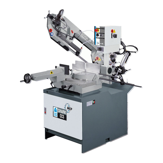
EEC safety standards. The SHARK 282 is structurally rigid, silent and safe: it produces a minimum of waste (1.2 mm) while its great versatility makes it suitable for cutting various materials such as stainless steel light alloys, aluminium, copper and bronze at high speed and with high precision. -
Page 10: Machine Presentation
Both the Automatic Vice and the Cut Control System are optional for the Warning SHARK 282 model; they can be factory installed on request made during the ordering procedure, or may be installed by the user after the machine has been bought. -
Page 11: Dimensions 1
CUTTING SPEEDS 1st Slow Speed mt/min 2nd Fast Speed mt/min All models can be equipped with the Inverter, an optional device, which offers Warning a range of speeds comprised between 20 and 90 mt/min As the machine is predisposed for the Inverter, it can be installed by the client or factory pre--installed on request made during the ordering procedure. - Page 12 Protection rating IP 55. Conforming to CEI norms, publication: IEC 34 of 01/07/1985. CUTTING CAPACITY Section 0° 280 x 220 45° a 220 x 200 60° a 140 x 80 45° ' 200 x 140 Use and maintenance manual SHARK 282 1- -4...
- Page 13 PACKED WEIGHT Wooden cage and pallet Wooden pallet 1900 1700 1000 Introduction and technical specifications 1- -5...
-
Page 14: Dimensions
MEP S.p.A. Dimensions MACHINE INSTALLED Work table height Weight 1800 Use and maintenance manual SHARK 282 1- -6... -
Page 15: Functional Parts
Functional parts SHARK 282 model In order for the user to move towards a full understanding of how the machine works, which is described in detail in the chapter 5, this chapter deals with the main units and their locations. -
Page 16: Cutting Head
The vice is operated manually by a handwheel, or by a pneumatic cylinder in the MA version (optional). Slideway Turntable Handwheel Vice support (lead nut) Fixed platform Use and maintenance manual SHARK 282 2- -2... -
Page 17: Control Panel
Control Panel The control panel has a protection rating of IP 54 and contains the electrical equipment. Access is gained by removing the screws fastening a safety panel, while the operator’s safety is guaranteed by a key---operated safety switch, designed to prevent any intentional interference with the unit. In order to remove the panel from its mounting, the main switch has to be shifted to 0 (OFF), which automatically cuts off the electrical supply. -
Page 18: Base
On opening the door in the base, you will find the air treatment unit (optional extra only on versions with MA automatic vice) and the drawer with the coolant, complete with electric pump. Electric pump Lubricant/coolant tank Use and maintenance manual SHARK 282 2- -4... -
Page 19: Safety And Accident Prevention
Safety and accident prevention The SHARK 282 has been designed and produced in accordance with European standards. For the correct use of the machine we recommend that the instructions contained in this chapter are carefully followed. Use of the machine The SHARK 282 band saw cutting machine is intended exclusively for cutting metallic materials, ferrous or non---ferrous, in section or solid. -
Page 20: General Recommendations
The installation of the earthing system must comply with the requirements set out in IEC STANDARD 204. OPERATOR POSITION The position of the operator controlling machine operations must be as shown in the diagram below. Use and maintenance manual SHARK 282 3- -2... -
Page 21: Recommendations To The Operator
Recommendations to the operator Always wear proper goggles or protective glasses. Do not use the machine without the guards in position. Replace the polycarbonate windows, if subject to corrosion. Do not allow hands or arms to encroach on the cutting zone while the machine is in operation. - Page 22 Warning: if the blade jams in the cut, press the emergency stop push---button immediately. If this does not free the blade, slowly loosen the vice, remove the piece and check the blade or blade teeth for breakage. Replace the blade if necessary. Use and maintenance manual SHARK 282 3- -4...
-
Page 23: Machine Safety Devices
Before carrying out any repair work on the machine, consult the MEP Technical Assistance Service: this can be done through a representative in the country of use of the machine. Adjustment of the blade---guide head must only be carried out with the machine at a standstill. -
Page 24: Protection Against Accidental Contact With The Blade
Use and maintenance manual SHARK 282 3- -6... -
Page 25: Emergency Devices
...Emergency devices applicable to the SHARK 282: 1. Emergency stop: a non---return mushroom---head pushbutton, colour red on yellow background, is located on the control panel of the machine. To release the pushbutton, the actuator must be rotated 45°... -
Page 26: Noise Level Of The Machine
MACHINES DIRECTIVE 2006/42/CE , we are listing the standards that specify noise levels for machine tools. This chapter also reports the noise levels produced by the SHARK 282 during its various operating phases and the methods used for measuring these levels. The Italian standard governing this aspect is D.M.n.277/91 drawn from EEC Directives 80/1107, 82/605, 83/477, 86/188, 88/642,... -
Page 27: Vibration Emission
The following text contains a list of the applied standards and the results of the electromagnetic compatibility testing of machine model SHARK 282; Test report no. 061200. Emissions CEI EN 61000- -6- -4 (2002) Electromagnetic Compatibility (EMC) - - Generic standard regarding emissions. - Page 28 CEI EN 61000- -6- -2 (2000) Electromagnetic Compatibility (EMC) - - Generic standard on immunity. Part 6- -2: Industrial Environment. The EUT is deemed to fulfil the immunity requirements without testing, because it contains no electonic control circuitry. Use and maintenance manual SHARK 282 3- -10...
-
Page 29: Machine Installation
Machine installation Packaging and storage MEP S.p.A. use packing materials that guarantee the integrity and protection of the machine during its transport to the customer. The type of packing differs according to the size, weight and destination. Therefore the customer will receive the machine in one of two following ways: 1. - Page 30 To install the machine, first remove the packing, paying particular attention not to cut any electric wires or hydraulic hoses; if necessary use pliers, a hammer and a cutter. Open crate in the illustrated order: Use and maintenance manual SHARK 282 4- -2...
- Page 31 1. remove nails and lift the top of the cage; 2. remove nails and lower walls; 3. remove heat---shrink covering; 4. remove the straps; 5. remove nails from pallet securing planks and remove planks; 6. remove the front panel and insert fork tines. To locate the machine in the workplace, the machine dimensions and necessary operator working space, including the spaces laid down in safety standards, must be taken into account.
-
Page 32: Anchoring The Machine
90%; lighting: not less than 500 Lux. The machine is already protected against voltage variations, but will only run Warning trouble--free if the variations do not exceed ± 10%. Use and maintenance manual SHARK 282 4- -4... -
Page 33: Check List
Check list Before starting installation, check that all the accessories, whether standard or optional, supplied with the machine are present. The basic version of the SHARK 282 2---SPEED machine is supplied complete with: CHARACTERISTICS STANDARD OPTIONAL Base with large swarf collection drawer, removable coolant tank and electropump for band saw lubrication/cooling Double return spring for head upstroke Hydraulic transducer for blade tension display... -
Page 34: Balancing The Cutting Head
1 - DOWN PIPE 2 - CONDENSATE COLLECTOR 3 - DRAIN COCK 4 - AIR FILTER 5 - DRAIN COCK 6 - CONNECTING HOSE Use and maintenance manual SHARK 282 4- -6... -
Page 35: Connection To The Power Supply
Connection to the power supply Before connecting the machine to the power supply, check that the socket is not connected in series with other machines. This requirement is fundamental for the good operation of the machine. To connect the machine to the power supply, proceed as follows: "... - Page 36 The sawing machine is now ready to start the work for which it was designed. Chapter 5 provides a detailed description of the various functions of the machine and its operating cycles. Use and maintenance manual SHARK 282 4- -8...
-
Page 37: Description Of Machine Operation
Description of the control panel The components of the SHARK 282 control panel are shown in the diagram below. Each arrow has a number which corresponds to the descriptions that follow. - Page 38 --- being a red button on a yellow background. To reset the emergency button, rotate actuator by 45° . OPTIONAL PEDAL FOR VERSION WITH AUTOMATIC VICE (MA) The foot pedal opens and closes the vice during normal machine operation. Use and maintenance manual SHARK 282 5- -2...
- Page 39 HEAD CONTROL LEVER MICROSWITCH The grip of the manual head control lever incorporates a microswitch for manual control of the blade motor. Microswitch Operating lever The microswitch is enabled when the machine is not in emergency state. In compliance with the relevant existing standards, voltage is 24V and the microswitch is installed in a housing (blue knob) sealed against external agents such as dust or moisture, with a protection rating of IP 55.
-
Page 40: Basic Instructions For Carrying Out A Cutting Operation Cycle
Also, the grip on the head control lever enables the operator to achieve a firm grip in order to start up band saw rotation by pressing the microswitch start lever, located in the handle itself. Use and maintenance manual SHARK 282 5- -4... -
Page 41: Clamping The Work Piece In The Vice
Clamping the work piece in the vice In the basic version, the work piece is clamped in the vice by rotating the opening/closing handwheel (in a clockwise/anticlockwise direction), as shown: " each time the vice is closed make certain that the work piece is solidly clamped. -
Page 42: Rapid Vice Positioning
For inclined cuts move the vice to the left or right, sliding it on the sliding guide. " Loosen the locking lever as indicated in the figure; " position the vice to the right or left and tighten the locking lever; Use and maintenance manual SHARK 282 5- -6... -
Page 43: Width Of Cut
Width of cut The machine is fitted with protections which protect the entire blade stroke, leaving exposed only the part of the blade required to make the cut itself as specified by current standards. The width of the cut is determined by the longitudinal section of the workpiece, so that only the part of the blade required to make the cut is actually exposed. -
Page 44: Preliminary Check List For Cutting Operation
" Clamp the workpiece in the vice; If the machine is the MA version, bring the vice manually to within 2---3 mm. of the workpiece ; tighten the vice using the special open/close button on the base or using the foot---pedal if equipped. 2--3 mm Use and maintenance manual SHARK 282 5- -8... - Page 45 " Select the cut using the polarity change switch according to the type of the material to be cut (shape, thickness, hardness, etc.). " Grip the head control lever and start the blade rotating by pressing the microswitch on the handgrip; the downstroke speed of the head is manually controlled by the operator.
- Page 46 If the machine is equipped with the Cut Control System, make sure that the Warning function selector switch is positioned on Manual and that the head return spring is tensioned in the Manual position. Use and maintenance manual SHARK 282 5- -10...
-
Page 47: Ccs (Cut Control System) Functioning Cycle
CCS (Cut Control System) functioning cycle The Cut Control System is an optional enabling both a Manual and a Semiautomatic/Dynamic work cycle to be performed. Sequence of operations for carrying out a cut in Semiautomatic/Dynamic mode: " power up the machine by turning the main switch; "... - Page 48 Semi---automatic or Dynamic and then press microswitch on the handgrip to start up blade rotation. " The operating head will now perform cutting until it reaches HDL (Head Downstroke Limit) at which point the motor will stop. Use and maintenance manual SHARK 282 5- -12...
-
Page 49: Angled Cuts
Angled cuts The machine can make angled cuts from 60° left to 45° right. Reference stops are mounted on the sides of the turntable to facilitate rapid 0° , 45° and 60° cuts to the left and 45° cuts to the right. Angled cuts 45°... -
Page 50: Angled Cuts 60° To The Left
Angled cuts 60° to the left " Undo the bush on the 45° left reference stop, as illustrated in the figure below, using a 36 mm wrench; " Slacken the turntable lock/release lever; Use and maintenance manual SHARK 282 5- -14... - Page 51 " pull the eccentric pin knob towards you (0° reference stop) and rotate slightly to raise it; " swing the head from left to right until it is positioned at the required angle, as indicated by the graduated scale on the turntable; "...
-
Page 52: Angled Cuts 45° To The Right
" relock the turntable lock/release lever; " make the cut in the required operating mode, following the preliminary safety instructions set out in this chapter. Use and maintenance manual SHARK 282 5- -16... -
Page 53: Diagrams, Exploded Views And Replacement Parts
This chapter contains functional diagrams and exploded views of the SHARK 282, including the MA version. This document is intended to help in identifying the location of the various components making up the machine, giving information useful in carrying out repair and maintenance operations;... -
Page 54: How To Read The Wiring Diagrams
Indications of the model of machine Indication of the Indications of the date production page number started MARIO ROSSI Identification of the designer Identification of the Reference Standard Use and maintenance manual SHARK 282 6- -2... - Page 55 Each component in the wiring diagram is identified by a unique alphanumeric identification code, in compliance with regulations: This symbol identifies the wire The wire is identified by the with its relative number and code ---W4 colour These symbols, known as potentials, are used to The motor is identified by the code ---M1 provide page references: the first number indicates the page to be referred to, the second number, after...
- Page 56 Devices not specified in this table Protective Devices Lightning protectors Arrestors Instant action current threshold protector Delayed action current threshold protector Instant and delayed action current threshold protector Fuse Voltage threshold protector Use and maintenance manual SHARK 282 6- -4...
- Page 57 LETTER TYPE OF COMPONENT EXAMPLES IDENTIFICATION OF THE APPLIANCE Generators, feeders Rotating generators Crystal oscillators Accumulator battery Rotating or static frequency converter Power feeder Signaling Devices Buzzer Optical signal, indicator light device Relays, Contactors Instant all or nothing relays or instant contactors Bistable relays or interdependent contactors...
- Page 58 Test plug Plug Socket Terminal connector band Electrically operated mechanical Electromagnet appliances Electromagnetic brake Electromagnetic clutch Magnetic table spindle Electromagnetic valve Transformers, impedence Line equalizer adapters, equalizers, band Compresser limiters Crystal filter Use and maintenance manual SHARK 282 6- -6...
-
Page 59: Standardised Wiring Diagrams (Cenelec Standard)
Standardised Wiring Diagrams (CENELEC Standard) Diagrams, exploded views and replace-- 6- -7... - Page 60 MEP S.p.A. Use and maintenance manual SHARK 282 6- -8...
-
Page 61: Exploded Views 6
Diagrams, exploded views and replace-- 6- -9... - Page 62 MEP S.p.A. Use and maintenance manual SHARK 282 6- -10...
- Page 63 Diagrams, exploded views and replace-- 6- -11...
- Page 64 MEP S.p.A. Use and maintenance manual SHARK 282 6- -12...
- Page 65 Diagrams, exploded views and replace-- 6- -13...
- Page 66 MEP S.p.A. Use and maintenance manual SHARK 282 6- -14...
- Page 67 Diagrams, exploded views and replace-- 6- -15...
- Page 68 MEP S.p.A. Use and maintenance manual SHARK 282 6- -16...
- Page 69 Diagrams, exploded views and replace-- 6- -17...
- Page 70 MEP S.p.A. Use and maintenance manual SHARK 282 6- -18...
- Page 71 Diagrams, exploded views and replace-- 6- -19...
- Page 72 MEP S.p.A. Use and maintenance manual SHARK 282 6- -20...
-
Page 74: Exploded Views
MEP S.p.A. Exploded views This part of the manual contains detailed exploded views of the machine which can help to gain a deeper knowledge of how it is made. Motor assembly 6- - 22 Use and maintenance manual SHARK 282... - Page 75 Code Description Quantity U. of M. 001.4254 PULEGGIA MOTRICE 1,000 007.4092 ALBERO RIDUTTORE 1,000 010.0355 GHIERA AUTOBLOCCANTE 25X1,5 1,000 010.0376 GHIERA FISSAGGIO ALBERO RIDUTTORE 1,000 010.7111 CHIAVETTA 8 X 7 X 32 1,000 010.7112 CHIAVETTA 8 X 7 X 35 1,000 010.7604 RONDELLA DIAM.
-
Page 76: Front Flywheel Assembly
MEP S.p.A. Front flywheel assembly Use and maintenance manual SHARK 282 6- -24... - Page 77 TAPPO TTE4 1/4 -- CL 2611 1,000 043.0275 NIPPLO CONICO A2--1/4 -- CL 2500 1,000 043.0350 GUARNIZIONE GFV 1/4 2,000 043.0556 MANOMETRO DIAM.50 0--60 X TENS.LAMA 1,000 043.0652 RUBINETTO 1/4 F.M. 1,000 090.0271 IMPUGNATURA COMPLETA TIPO MEP 1,000 6- -25...
-
Page 78: Motor Flywheel Assembly
MEP S.p.A. Motor flywheel assembly Use and maintenance manual SHARK 282 6- -26... - Page 79 Code Description Quantity U. of M. 001.4222 ARCHETTO SEZIONE PULEGGIA MOTRICE 1,000 007.3812 DISTANZIALE CUSCINETTO SNODO TESTA 1,000 007.3813 DISTANZIALE ARCHETTO 1,000 007.3822 PERNO SUPPORTO SNODO TESTA 1,000 007.4006 STAFFA TESTINA GUIDALAMA POSTERIORE 1,000 007.4057 BOCCOLA BATTUTA FINE CORSA 1,000 010.0315 VITE 8.8 T.E.
-
Page 80: Cutting Head Cover
MEP S.p.A. Cutting head cover Use and maintenance manual SHARK 282 6- -28... - Page 81 Code Description Quantity U. of M. 010.7601 RONDELLA DIAM. 4 2,000 010.7850 VITE TCEI 4 X 8 2,000 010.7990 VITE TSPEI 4 X 8 2,000 010.7993 VITE TSPEI 5 X 12 4,000 016.0250 COPERCHIO ARCHETTO 1,000 016.1224 PIASTR.FIX INTER.SICUR.COPERCHIO 1,000 034.1107 VOLANTINO DIAM.30 M6 X 20 2,000...
-
Page 82: Vice Assembly
MEP S.p.A. Vice assembly Use and maintenance manual SHARK 282 6- -30... - Page 83 Code Description Quantity U. of M. 001.4007 SCORREVOLE MORSA 1,000 001.4037 SUPPORTO MORSA 1,000 007.3824 PERNO BLOCCAGGIO MORSA MSR 1,000 007.3839 LARDONE MORSA 1,000 007.4058 BOCCOLA ECCENTRICA 1,000 007.4081 PIGNONE SBLOCCAGGIO SCORREVOLE 1,000 010.0244 VITE MORSA 1,000 010.0549 GANASCIA MORSA MOBILE SH 270 1,000 010.0918 MOLLA RICHIAMO CHIOCC.VITE MORSA...
-
Page 84: Base Assembly
MEP S.p.A. Base assembly Use and maintenance manual SHARK 282 6- -32... - Page 85 Code Description Quantity U. of M. 010.1803 CHIUSURA SPORTELLO PIEDISTALLO 1,000 010.1881 CERNIERA SPORTELLO PIEDISTALLO 2,000 010.7208 DADO M16 1,000 010.7603 RONDELLA DIAM. 6 2,000 010.7606 RONDELLA DIAM. 12 2,000 010.7868 VITE TCEI 6 X 12 2,000 010.7871 VITE TCEI 6 X 20 2,000 010.7972 VITE TE 16X60...
-
Page 86: Control Panel
MEP S.p.A. Control panel Use and maintenance manual SHARK 282 6- -34... - Page 87 Code Description Quantity U. of M. 010.7604 RONDELLA DIAM. 8 4,000 010.7830 VITE BUTON 5 X 10 10,000 010.7893 VITE TCEI 8 X 20 4,000 016.0708 QUADRO COMANDI LVD 1,000 022.0211 RACCORDO RAPIDO SEM PG 13,5 2,000 022.0234 PRESSACORDONE 3246 NERO PG 13,5 2,000 022.0244 CONTRODADO 3217B GRIGIO PG 13...
-
Page 88: Handgrip
MEP S.p.A. Handgrip Use and maintenance manual SHARK 282 6- -36... - Page 89 GRANO VCE P.CIL. 8 X 10 1,000 010.7700 SPINA CILINDRICA DIAM. 4 X 24 1,000 010.7800 VITE AUTOFILETTANTE 2,9 X 15 3,000 022.0515 MICROINTERRUTTORE V--21--1C6 1,000 025.0691 SERIE GUARNIZIONI X IMPUGNATURA MEP 1,000 034.1221 IMPUGNATURA DIS. MEP 1,000 6- -37...
-
Page 90: Fixed Work Table And Turntable
MEP S.p.A. Fixed work table and turntable Use and maintenance manual SHARK 282 6- -38... - Page 91 Code Description Quantity U. of M. 001.3111 DISTANZIALE BATTUTA 1,000 001.4705 PIATTAFORMA FISSA SH 270 1,000 001.4702 PIANO ROTANTE SH 270 1,000 002.0101 SQUADRO MORSA SINISTRO 1,000 002.0102 SQUADRO MORSA DESTRO 1,000 007.3819 PERNO DI CENTRO 1,000 007.3827 BOCCOLA PER BATTUTA 1,000 007.3895 BOCCOLA 0 38 X RULLO...
-
Page 92: Optional Cut Control System
MEP S.p.A. Optional Cut Control System Use and maintenance manual SHARK 282 6- -40... - Page 93 Code Description Quantity U. of M. 007.4209 PROLUNGA CILINDRO 1,000 010.0899 MOLLA RICHIAMO TESTA 1,000 010.1103 FORCELLA 16 X 1,5 1,000 010.1470 STAFFA SUPPORTO CILINDRO 1,000 010.1465 STAFFA AGGANCIO MOLLA 1,000 010.1507 STAFFA FIX F.C. CONTROLLO TAGLIO 1,000 010.7203 DADO M6 2,000 010.7605 RONDELLA DIAM.
-
Page 94: Supplementary Pneumatic Vice
MEP S.p.A. Supplementary pneumatic vice Use and maintenance manual SHARK 282 6- -42... - Page 95 Code Description Quantity U. of M. 010.0244 VITE MORSA 1,000 010.7410 VITE VCEI PUNTA CILINDRICA M8X16 1,000 010.7455 VITE VCEI PUNTA CONICA M8X10 1,000 010.7893 M8X20--TCEI 1,000 016.1214 PANNELLO--PNEUMATICO--SH280--320 1,000 034.0205 VOLANTINO--MORSA--125 1,000 034.0417 COPERCHIO--PED--MA 1,000 043.0044 CIL--PN--D100 1,000 043.0204 ATTACCO--A--GOMITO--8X1_4--CL6521 3,000 043.0205...
-
Page 97: Adjustments
Adjustments This chapter illustrates the regulations and adjustments of the mechanical systems (pneumatic systems in the MA version) for correct use of SHARK 282. These instructions will enable you to “customise” your machine to suit the type of cuts you want, optimising the time required to complete them. -
Page 98: Topping Up And Bleeding The Cylinder (Cut Control System Optional)
To top up the oil in the tank, the instructions are as follows: " keep the head in the HUL position (fully up) by closing the head descent reg- ulator; " unscrew the filler valve cap; Use and maintenance manual SHARK 282 7- -2... -
Page 99: Bleeding The Head Cylinder
" using a manual pump, loaded with MOBIL DTE 11 oil (or equivalent --- see table in Chapter 8), top up until the upper rod groove exits, as illustrated above. Bleeding the head cylinder Accumulations of air inside the hydraulic circuit cause the head to stutter in down phase. -
Page 100: Vice
" close the vice until two more grub screws are in the same position as the first two previously; " repeat the operation on the gib grub screws on all the slideway grub screws; Use and maintenance manual SHARK 282 7- -4... -
Page 101: Cutting Head
" at the end of the operation, use the handwheel to move the slideway back and forth, identifying the zones where the grub screws exert greater pressure on the gib. Cutting head Blade tensioner slide play adjustment To reduce the play which develops over a period of time between the blade tensioner slide and the slide gibs, the grub screws separating the gibs from the slide must be adjusted as follows: "... -
Page 102: Blade Tensioning Unit
20 mm Topping up sequence: " lower the head; " slacken the blade tensioning handwheel; " remove the filler cap using a hex wrench; Use and maintenance manual SHARK 282 7- -6... - Page 103 " pull out the piston, if necessary, using a pair of pliers, until it protrudes 44 mm from the cylinder; " top up with AGIP ATF DEXRON oil or one with similar characteristics using a funnel. " screw on the filler cap; "...
-
Page 104: Adjusting Operating Head Travel
" The CCS has an electrical limiter, functioning as HDL, located on the back of the machine; according to the type of work cycle to be carried out, the dis- tance of the limiter from the striker can be regulated by adjusting the support plate screws. Use and maintenance manual SHARK 282 7- -8... -
Page 105: Blade Guide Parts
Blade guide parts Band saw blades offer enormous advantages to cutting applications, without requiring any special skills by the operator. A description follows of the blade guide adjustments required to ensure correct operation of the saw. Blade guide heads The first blade adjustment involves adjustment of the heads. The blade guide heads comprise the blade guide plates which ensure correct longitudinal align- ment, the blade steady buttons which control vertical blade flexure, and the coolant supply cocks. - Page 106 " open the front blade guard by undoing the fixing screw and rotating it as illus- trated in the figure below; " wear protective gloves when making this adjustment; " make sure there is a small amount of play between the blade and guide plate inserts; Use and maintenance manual SHARK 282 7- -10...
- Page 107 " if the amount of play is not sufficient for the blade to run smoothly, adjust the locking torque of the two grub screws with an Allen key; " replace any worn plates by removing the plate fixing screw; " repeat the above sequence of steps on the rear blade guide head; "...
-
Page 108: Blade
" open the cutting head cover by unscrewing the two knobs and hooking it onto the galvanised lever on the back of the head; " open the front blade guard by undoing the fixing screw and rotating it as illus- trated in the figure below; Use and maintenance manual SHARK 282 7- -12... - Page 109 " remove the rear blade guard by undoing the two fixing screws using an Allen key; " wear protective gloves when changing the blade; " remove the worn blade by sliding it off the flywheels and front and rear heads; "...
-
Page 110: Blade Perpendicularity
If the point of contact is at the upper part, slacken the TCEI screw (A’) and tighten grub screws (B’) equally until the blade is perpendicular to the square. Use and maintenance manual SHARK 282 7- -14... -
Page 111: Orthogonality Of The Blade
" Position the square on the work surface close to the front head. " Repeat the squaring operations as for the rear head. Orthogonality of the blade The procedure for correcting and adjusting the blade to 0° and 45° right and 45° and 60°... - Page 112 Operation sequence for blade adjustment to 45 degrees: " slacken the turntable lock/release lever; " turn the head to 45 degrees (left or right); Use and maintenance manual SHARK 282 7- -16...
- Page 113 " position the goniometer on the work table and measure the angle between the vice jaw and blade; " once you have identified the degree of error, adjust the pins by gripping the pin with an Allen key and slackening the lock nut with a normal wrench; "...
- Page 114 MEP S.p.A. To adjust the blade to 60 degrees left, proceed as described above for a 45 degree angle, this time however, adjusting the stop indicated in the drawing below. Use and maintenance manual SHARK 282 7- -18...
-
Page 115: Front Flywheel
Front flywheel The front flywheel must be adjusted so that it is aligned with the rear wheel. The purpose of this adjustment is to make sure the back of the blade remains about 1 mm from the edge of the flywheel during rotation. This prevents premature wear to the blade which, due to excessive friction with the edge, may crack. -
Page 116: Motor Flywheel
" To adjust, slacken all the locking screws on the flywheel and manually move it in or out until the blade is correctly distanced from the edge of the wheel. Retighten the screws and check alignment by rotating the blade a few times. If necessary, readjust. Use and maintenance manual SHARK 282 7- -20... -
Page 117: Maintenance And Choice Of Consumables
SHARK 282 is built to be sturdy and long---lasting It has no need of any special maintenance, though, like all other tools, it needs adjusting from time to time, especially if not regularly looked over or used without due care. -
Page 118: Maintenance Requirements
All ordinary and extraordinary maintenance must be carried out with the power switched off and the machine in emergency condition. To guarantee perfect operation, all spare parts must be MEP S.p.A originals. On completion of maintenance works, ensure that the replaced parts or any tools used have been removed from the machine before starting it up. -
Page 119: Monthly
" check oil level in the CCS optional hydraulic cylinder (Chapter 7). Maintenance of working parts In maintenance work on the SHARK 282, special attention should be paid to operating units such as the blade tensioning cylinder, already dealt with in Chapter 7, topping up levels, the air treatment unit, the pneumatic vice on the MA version, and the optional CUT CONTROL SYSTEM. -
Page 120: Oils For Cut Control System Hydraulic Circuit
Oil for lubricant/coolant fluid The oil used for the machine lubricant/coolant fluid is CASTROL Syntolin TFX. Though there are no specific standards for these types of oils, MEP considers that the above product has the best price/quality rapport. The following oils can... -
Page 121: Cutting Speed And Choice Of Tools
(inverter) is necessary. When using the SHARK 282, it is important to select the correct type of blade for the material to be cut. This chapter explains the limitations and specific applications of the different types of blades. -
Page 122: Machine With Inverter (Optional)
MEP S.p.A. Machine with Inverter (optional) The inverter is an electronic instrument fitted to the SHARK 282 for varying spindle motor rpm. The inverter makes life easier for the operator carrying out special cutting tasks by enabling a changing of rotation speed to suit the kind of material being cut. -
Page 123: Choice Of Blade
Choice of blade When using band saws to cut metals, an important factor is the choice of pitch, i.e. the number of teeth per inch (25.4 mm.), which must be suitable for the workpiece material. The following recommendations may be taken as general guidelines: thin---walled materials, such as sheet steel, tubes and profiles require a fine pitch frequency. -
Page 124: Cutting Speed And Downstroke Speed
300 --- 600 cm Types of swarf: Very fine or fragmented swarf indicates that the downstroke speed and/or cutting pressure is too low. Thick and/or blue swarf indicates that the blade is overloaded. Use and maintenance manual SHARK 282 9- -4... -
Page 125: Lubricant/Coolant Fluid
Long coils of swarf indicate ideal cutting conditions. Lubricant/coolant fluid The lubricant/coolant fluid must ensure so that neither the saw teeth nor the work piece material in the cutting zone overheat. Furthermore, there must be a sufficient quantity and pressure of lubricant/coolant to remove swarf from the cutting zone. -
Page 126: Blade Structure
N.B. Blade types The blades mounted on the SHARK 282 are 2.950 x 27 x 0.9 mm.; the length can vary between 2.960 mm. and 2.940 mm., thanks to the blade tensioner device. The blades, however, apart from size and tooth pitch, are differentiated by other geometrical characteristics which determine their specialised uses: tooth cutting angle (rake), can be 0 or positive;... -
Page 127: Conventional Rake
Conventional rake Cutting angle 0° , constant pitch. In general use, for small or medium section cast iron or steels and rolled materials, for straight or angled cuts. Positive rake Positive cutting angle 9---10° , constant pitch. Can be used for cutting all types of materials, and is particularly suited to low---carbon and non---ferrous steels. -
Page 128: Variable Pitch Blades With 0° Cutting Angle
Standard or splayed set This term is used to describe an alternated angling of the teeth: one to the right, one to the left and one straight. Use and maintenance manual SHARK 282 9- -8... -
Page 129: Undulated Set
For general use on materials over 5 mm. thick. Suitable for cutting steels, castings and non---ferrous hard materials. Undulated set Used to describe groups of teeth undulating alternatively to the right and left. This type of set is used with very fine teeth for cutting thin pipe walls and small---section profiles (from 1 to 3 mm). -
Page 130: Blade Selection Table Relating To Cutting Speed And Downstroke Speed
MEP S.p.A. Blade selection table relating to cutting speed and downstroke speed Use and maintenance manual SHARK 282 9- -10... -
Page 131: Classification Of Steels
Classification of steels This page provides a table giving the user specific information on the cutting materials, in order that they can be classified on the basis of their hardness, and thus the correct tool can be selected for the task in hand. Cutting speed and choice of tools 9- -11... -
Page 132: Classification Of Steels 9
MEP S.p.A. Classification of steels Use and maintenance manual SHARK 282 9- -12... -
Page 133: Troubleshooting
Troubleshooting This chapter describes the inspection and troubleshooting procedures for the SHARK 282. Regular inspections and efficient maintenance are essential to ensure your machine gives you a long, trouble---free service life. The chapter is divided into two sections: the first being dedicated specifically to... - Page 134 Tooth shape or pitch unacceptable: change type of blade used. Widia blade steady buttons too far from the blade back: adjust guide heads, rotating them slightly to bring them closer to the blade back. Use and maintenance manual SHARK 282 10- -2...
- Page 135 PROBLEM PROBABLE CAUSE SOLUTION Cuts not orthogonal or inclined ' Head downstroke speed too .Reduce head downstroke fast speed ' Widia inserts worn .Replace ' Inserts loose .Adjust width ' Blade guide head positioned .Move mobile head up to the wrongly workpiece using the guide plate to leave free only that...
- Page 136 A tooth from the old blade may be left in the cut: check and remove before restarting work. Use and maintenance manual SHARK 282 10- -4...
- Page 137 PROBLEM PROBABLE CAUSE SOLUTION Broken teeth ' Widia inserts positioned .Adjust the position of the incorrectly inserts, especially the width, since blade thicknesses can exceed the manufacturer’s declared tolerance ratings ' Widia blade steady buttons .Two widia blade steady buttons are located in the top of the blade guide heads which press on the back of the blade to transmit cutting...
- Page 138 ' Blade weld fault .The point at which a blade is welded is its most critical point; problems could be caused by welds which are not aligned perfectly or have inclusions or blowholes Use and maintenance manual SHARK 282 10- -6...
- Page 139 PROBLEM PROBABLE CAUSE SOLUTION ' Free blade guide head .The head is too far away from the workpiece: move the head closer, leaving free only that part of the blade actually needed to make the cut ' Teeth in contact with the .Always check the position of material before starting the the blade before starting a...
-
Page 140: Troubleshooting Machine Faults
.Check that the closure is correct and the limit stop pressed ' Current drop .Check connections on the handgrip switch, the blade protection limiter and the pressure gauge on the blade tensioner group Use and maintenance manual SHARK 282 10- -8... - Page 141 PROBLEM PROBABLE CAUSE SOLUTION BMT not energised (Minimum ' Electrical power supply .Check: the phases; the Tension Coil) cables; the plug; the socket. ' BMT Reset switch .Make sure that the minimum tension coil is energised when switch is turned from 0 to 1.
- Page 142 .Check that the spring is correctly tensioned ' Cylinder .Check that hydraulic circuit oil level is sufficient. ' Limiter .Check connections and functioning ' Head control lever .Check connections and microswitch functioning Use and maintenance manual SHARK 282 10- -10...
-
Page 143: Accessory Installation
Accessory Installation This chapter provides a list of the available accessories that can be fitted to this machine, along with assembly instructions. Automatic vice kit This pneumatic device can be activated by using the selector on the front of the machine base. -
Page 144: Blade
This accessory allows you to run a Semi---automatic / Dynamic work cycle as described in Chapter 5 of this manual. An instruction book is supplied with the kit to explain how to install this optional unit. Use and maintenance manual SHARK 282 11- -2... -
Page 145: Electronic Rpm Variator (Inverter)
Electronic rpm variator (inverter) This device provides a speed range of between 20 ÷ 90 m/min Open the door in the base and fix the inverter to the bottom, positioning it about 10 cm from the rear and right walls. Form two threaded holes for fixing the inverter casing. - Page 146 MEP S.p.A. form the connections as shown in the layout below: Use and maintenance manual SHARK 282 11- -4...
-
Page 147: Rod Marked Off In Millimetres
Rod marked off in millimetres This device is used to measure the length of the pieces to be cut. To fit this accessory on the machine: screw the support for the rod marked off in millimetres to the existing seating on the discharge side of the fixed turntable as shown in the figure. -
Page 148: Roller Table
-support arm that one end of the roller- -way can be positioned on and then screwed in place. To install the roller loading platform on the discharge side an adapter must be used, with or without a support, as explained in the paragraphs that follow. Use and maintenance manual SHARK 282 11- -6... -
Page 149: Support For The Roller Platform On The Feeding/Discharging Side
Support for the roller platform on the feeding/discharging side This device is used to increase the load---bearing strength of the roller table, both during feeding and discharge. The steps which should be followed to assemble it are illustrated below. " disconnect the table from the adapter (on the discharge side, for example); "... -
Page 150: Discharge Side Roller Table Adaptoradattatore Pianale A Rulli Lato Scarico
" Attach the outfeed rolling deck by fixing it with the screws supplied. Use and maintenance manual SHARK 282 11- -8...
Need help?
Do you have a question about the SHARK 282 and is the answer not in the manual?
Questions and answers