Sign In
Upload
Manuals
Brands
Lombardini Manuals
Engine
4LD 820
Lombardini 4LD 820 Engine Spare Parts Manuals
Manuals and User Guides for Lombardini 4LD 820 Engine Spare Parts. We have
2
Lombardini 4LD 820 Engine Spare Parts manuals available for free PDF download: Workshop Manual
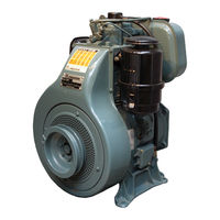
Lombardini 4LD 820 Workshop Manual (48 pages)
Engine Series 3 - 4 LD
Brand:
Lombardini
| Category:
Engine
| Size: 0.69 MB
Table of Contents
Table of Contents
4
3 LD 510, 3LD 451/S, 3LD 510/S, 4LD 640, 4LD 705, 4LD 820, Which Are Air-Cooled, Provided with Direct Injection and Revised
6
General Remarks and Safety Information
6
Safety Information
6
California Proposition 65
7
Regulations for Lifting the Engine
7
General Safety During Operating Phases
8
Safety and Enviromental Impact
8
Technical Information
10
Manufacturer and Motor Identification Data
10
Technical Data
11
Performance Diagrams
12
Possible Causes and Trouble Shooting
13
Table of Likely Anomalies and Their Symptoms
13
Capacities in Litres - Air Filter Oil Bowl
14
Capacities in Litres - Standard Fuel Tanks
14
Capacities in Litres - Standard Oil Sump
14
Routine Engine Maintenance
14
Lubricant - ACEA-Regulations Sequences
15
Lubricant - API-MIL Sequences
15
Lubricant - International Specifications
15
Lubricant - SAE Classification
15
Disassembly / Reassembly
16
Oil-Bath Air Filter (Standard)
16
Recommendations for Disassembling
16
Silencer (Standard)
16
Flywheel
17
Starting Pulley
17
Vent Plug
17
Decompression (by Request)
18
Rocker Arm Pin, Extraction
18
Head
19
Injector, Projection
19
Rocker Arm Pin and Hole
19
Valve/Rocker Arm Clearance
19
Valves
19
Valve Guide Dimensions and Clearances
20
Valve Guides Insertion
20
Valves Guides and Housings
20
Valve Housings and Seats
21
Valve Seat Grinding
21
Cylinder and Piston
22
Distance Among Segment Ends (MM)
22
Piston Ring - Clearances Among Slots (MM)
22
Clearance Volume
23
Piston Reassembly
23
Piston Ring Assembly Order
23
Connecting Rod Equipped with Bearings and Piston Pin
24
Connecting Rod, Big End Bearings
24
Drive Shaft Axial Clearance
24
Main Bearing on Flywheel Side
24
Camshaft Axial Clearance
25
Side Distributor Port
25
Drive Shaft
26
Drive Shaft Connecting Radius
26
Drive Shaft Lubrication Ducts
26
Drive Shaft Main Journal and Crank Diametres (MM)
26
Camshaft
27
Camshaft Intake and Exhaust Cam Timing
27
Drive Shaft Internal Diam. Crankshaft Bearing / Connecting Rod Head
27
And Clearances Regarding Their Respective Pins (MM)
27
Camshaft Intake and Exhaust Cam Height
28
Camshaft Pin and Housing Dimensions (MM)
28
Distribution Timing Without Following the References
28
Distribution Timing
28
Speed Governor
29
Timing of the Speed Governor
29
Lubrication Circuit
30
Oil Filter Cartridge
31
Oil Pump
31
Oil Pump, Difference between Clockwise Rotation Pump and Anticlockwise Pump
31
Oil Pressure Check
32
Oil Pressure Curve with the Engine at Its Maximum Speed
32
Oil Pressure Regulating Valve
32
Fuel Injection Circuit
33
Feeding Pump (by Request)
33
Feeding Pump Rod Projection
33
Fuel Filter Inside the Tank (Standard)
33
Standard Feeding/Injection Circuit
33
Advanced Injection (Static)
34
Injection Pump
34
Injection Pump Assembly
34
Advanced Injection References on the Conveyor and Flywheel Protection Disk
35
Injector
35
Injector Setting
35
Electric Circuit
36
14 A Electrical Ignition, Diagram with Voltage Regulator , Battery Recharge Lamp and Manostat
36
12,5 V, 14 a Alternator Battery Recharge Curve
36
12.5 V 14 a Alternator
36
Bosch DW (L) 12 V 1, 1 KW Type, Starting Motor
37
Voltage Regulator
37
Voltage Regulator, Running Check
37
Bosch JF(L) 12V 2.5 Kw Type, Starting Motor
38
Characteristic Curves for Bosch DW(L) 12V 1.1 Kw Type, Starting Motor
38
Characteristic Curves for Bosch JF(L) 12V 2,5 Kw Type Starting Motor
38
Adjustment
39
Injection Pump Delivery Adjustment (Standard)
39
Minimum Rpm Adjustment at Idle Running (Standard)
39
Peak Rpm Adjustment at Idle (Standard)
39
Adjustment of Injection Pump Delivery with Braked Engine
40
Limiting Device for Injection Pump Delivery and Torque Gearing Device
40
Required Adjustments (the most Demanded)
40
Storage
41
Protective Treatment
41
Preparing the Engine for Operation after Protective Treatment
41
Main Torque Specifications and Use of Sealants
42
Tightening Torques Main
42
Table of Tightening Torques for Standard Screws (Fine Thread)
43
Use Sealant
44
Advertisement
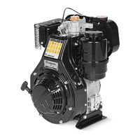
Lombardini 4LD 820 Workshop Manual (34 pages)
Brand:
Lombardini
| Category:
Engine
| Size: 1.38 MB
Table of Contents
Introduction
2
Index of Chapters
2
Registration Code and Identification
3
Characteristic Curves
4
Maintenance - Prescribed Oil - Refuellings
5
Rating
5
Capacities in Liters
5
Recommended Oil
5
Trouble Shooting
6
Flywheel
7
Disassembly/Reassembly
7
Silencer (Standard)
7
Oil-Bath Air Filter (Standard)
7
Starting Pulley
8
Vent Plug
8
Valve/Rocker Arm Clearance
8
Decompression (by Request)
8
Injector, Projection
9
Head
9
Rocker Arm Pin and Hole
9
Rocker Arm Pin, Extraction
9
Valves
10
Valves Guides and Housings
10
Valve Guides Insertion
10
Valve Guide Dimensions and Clearances
10
Valve Seat Grinding
11
Cylinder and Piston
11
Distance Among Segment Ends (MM)
11
Piston Reassembly
12
Piston Ring Assembly Order
12
Piston Ring - Clearances Among Slots (MM)
12
Clearance Volume
13
Connecting Rod Equipped with Bearings and Piston Pin
13
Connecting Rod, Big End Bearings
13
Main Bearing on Flywheel Side
13
Side Distributor Port
14
Camshaft Axial Clearance
14
Drive Shaft
14
Drive Shaft Lubrication Ducts
14
Drive Shaft Main Journal and Crank Diametres (MM)
15
Camshaft
15
Camshaft Pin and Housing Dimensions (MM)
16
Distribution Timing
16
Distribution Timing Without Following the References
16
Speed Governor
17
Timing of the Speed Governor
17
Lubrication Circuit
18
Oil Pump
18
Oil Pressure Check
19
Features
19
Oil Pressure Regulating Valve
19
Oil Filter Cartridge
19
Standard Feeding/Injection Circuit
20
Fuel Filter Inside the Tank (Standard)
20
Feeding Pump Rod Projection
20
VII Fuel/Injection Circuit
20
Injection Pump Assembly
21
Advanced Injection (Static)
21
Setting
21
VIII Electric Circuit
22
Electric Equipment
23
Voltage Regulator
23
Voltage Regulator, Running Check
23
IX Electric Equipment
24
Minimum Rpm Adjustment at Idle Running (Standard)
25
Peak Rpm Adjustment at Idle (Standard)
25
Injection Pump Delivery Adjustment (Standard)
25
X Adjustments
26
Required Adjustments (the most Demanded)
26
Adjustment of Injection Pump Delivery with Braked Engine
26
Upkeeping
27
Temporary Protection (1÷ 6 Months)
27
Permanent Protection (over 6 Months)
27
Preparation for the Setting at Work
27
XII Technical Data
28
Main Driving Torques
29
XIV Use of Sealant
30
Driving Torques
31
General Alphabetical Index
32
Advertisement
Related Products
Lombardini 4LD 705
Lombardini 4LD 640
Lombardini 11 LD 535-3
Lombardini 11 LD 625-3
Lombardini 11 LD 626-3
Lombardini 11 LD Series
Lombardini 11LD522-3 Series
Lombardini 12 LD 477/2
Lombardini 12LD 435-2
Lombardini 12LD 435-2/B1
Lombardini Categories
Engine
Air Conditioner
Controller
More Lombardini Manuals
Login
Sign In
OR
Sign in with Facebook
Sign in with Google
Upload manual
Upload from disk
Upload from URL