Sign In
Upload
Manuals
Brands
Lombardini Manuals
Engine
11 LD 626-3
Lombardini 11 LD 626-3 Diesel Engine Manuals
Manuals and User Guides for Lombardini 11 LD 626-3 Diesel Engine. We have
3
Lombardini 11 LD 626-3 Diesel Engine manuals available for free PDF download: Use And Maintenance, Workshop Manual
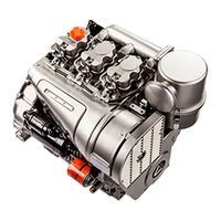
Lombardini 11 LD 626-3 Workshop Manual (106 pages)
11 LD series
Brand:
Lombardini
| Category:
Engine
| Size: 15.97 MB
Table of Contents
Table of Contents
3
1 General Remarks and Safety Information
7
Warranty Certificate
7
Glossary and Terminology
7
General Service Manual Notes
7
Safety Regulations
8
Safety and Warning Decals
8
General Safety During Operating Phases
9
Safety and Environmental Impact
9
2 Technical Information
10
Possible Causes and Trouble Shooting
10
Manufacturer and Motor Identification Data
12
Techinical Specifications
13
Performance Diagrams
14
Overall Dimensions
16
3 Maintenance- Recommended Oil Type - Refilling
17
Routine Engine Maintenance
17
Lubricant
18
SAE Classification
18
ACEA Regualtions - ACEA Sequences
18
International Specifications
18
API / MIL Sequences
19
Prescribed Lubricant
19
Fuel Specifications
20
Recommendations for Disassembling and Assembling
22
4 Disassembly / Reassembly
23
Exhaust Manifold
23
Belt Tension Adjustment
24
Blower Belt Alternator
24
Air Shroud and Baffles - Disassembly
25
Blower Assembly
25
Blower Belt Alternator - Reassembly
25
Blower Assembly Components with 14 a Alternator
26
Blower Assembly Components with 21 a Alternator
26
Blower Control Pulley - Disassembly
26
Blower Control Pulley Diameter
27
Flywheel
28
Valve / Rocker Arm Clearance
28
Compression Release
29
Cylinder Head
31
Valves
31
Valve Guides and Cylinder Head Housings
32
Valve Material
32
Valve Springs
32
Valve Stem Sealing Rings - Reassembly
32
Dimensions and Clearance between Guides and Valves
33
Valve Guide Insertion
33
Valve Seat Lapping
33
Valve Seats and Housings
33
Checks and Cyiinder Roughness
34
Metal Snap Rings - End Gaps
35
Connecting Rod
36
Connecting Rod Alignment
37
Camshaft Gear
38
Center Main Bearing Support, Locating Bolts
39
Checking Main Journals and Crank Pins
40
Clearance between Main Journals/Crank Pins and Connecting Rod Bearings
41
Camshaft
42
Camshaft Removal
42
Camshaft End Play
43
Camshaft Timing
44
Valve Timing Check
44
Valve Timing Without Considering Timing Marks
44
Hydraulic Pump 3Rd P.t.o., Group 2
46
Mechanical Speed Governor
47
Mechanical Speed Governor Components for Special Generating Sets
48
Lubrication System
49
Oil Filter Cartridge
50
Oil Pressure Check
50
Oil Pressure Relief Valve
50
Oil Pump
50
Oil Pressure Curve at Full Speed
51
Oil Pressure Curve at Idling Speed
51
Fuel Feeding Pump
52
Fuel Feeding/Injection Circuit
52
Fuel Filter
52
Fuel System
52
Injection Pump
52
Injection Pump Only for EPA Engines
53
Injection Pump Only for Standard and 97/68 Ce Engines
53
How to Check Injection Pump Delivery Valve Sealing
54
How to Check Plunger and Barrel for Internal Leakage
54
Plunger
54
Test Data for Injection Pump Delivery at the Test Bench for Standard and 97 / 68 CE Engines
55
Test Data for Injection Pump Delivery at the Test Bench Only for EPA Engines
55
Injection Pump Replacement
56
Size S Injector
56
Size P Injector
57
Size P Nozzle
57
Size S Nozzle
57
Injector Setting
58
Static Injection Timing
58
Electric Starting Layout Without Battery Charging Light
62
Electric System
62
Electrical Starting Layout with Battery Charging Iight
62
Standard Electric Equipment
62
V, 14 a Alternator
62
12 V, 21 a Alternator
63
Alternator Battery Charger Curve (12 V, 21 A)
63
Alternator Battery Charger Curve (12.5 V, 14A)
63
Checking for Cable Continuity
64
Magnetization Checking Tool
64
Voltage Regulator
64
How to Check Voltage Regulator for Proper Operation
65
33 A Bosch G1 Alternator Battery Charger Curve
66
Alternator Type Bosch G1 14 V, 33 a
66
Alternator Type Bosch Gil 14 V, 33 a Layout
66
V, 33 a Bosch G1 Alternator Battery Charger Curve
66
Characteristic Curves for Starting Motor Type Bosch JF (R) 12 V
67
Electric System ............................................................................................................................. 62
67
Starting Motor Layout
67
Starting Motor Type Bosch JF (R) 12 V, Class 2.5
67
Injection Pump Delivery Setting
68
Settings
68
Stop Setting
68
Engine
71
With Advance Variator
71
Advance Variator Operating Principle
72
Disassembly / Reassembly
89
External Engine Protection
100
Injection Systems Protection
100
Internal Engine Protection
100
Storage
100
Procedures to be Carried out before Start the Engine
101
Storage ____________________________________________________________________ 100
101
Main Torque Specifications
102
Main Torque Specifications and Use of Sealants
102
Use of Sealants
103
Table of Tightening Torques for Standard Screws (Coarse Thread)
104
Table of Tightening Torques for Standard Screws (Fine Thread)
104
Special Tools
105
Advertisement
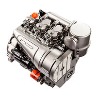
Lombardini 11 LD 626-3 Workshop Manual (68 pages)
Brand:
Lombardini
| Category:
Engine
| Size: 4.27 MB
Table of Contents
Hydraulic Pump 4Th P.t.o., Group
1
Hydraulic Pump 3Rd P.t.o., Group
2
Table of Contents
4
Itroubleshooting
9
Safety Decals - Safety Instructions
10
Model Number and Identification
12
4 Technical Data
13
5 Vcharacteristic Curves
14
6 Overall Dimensions
15
7 Maintenance- Recommended Oil Type - Refilling
16
8 Disassembly/Reassembly
19
Aír Cleaner
19
Air Cleaner Components
19
Exhaust Manifold
19
Belt Tension Adjustment
20
Fan Control Belt
20
Intake Manifold
20
Shroud and Plates
20
Blower Assembly
21
Blower Assembly Components with 14 a Alternator
21
Blower Assembly Components with 21 a Alternator
21
Blower Control Pulley Diameter
22
Crankshaft Pulley
22
Gear Cover, Timing Side
22
Tank
22
Compression Release (Optional)
23
Flywheel
23
Valve / Rocker Arm Clearance
23
Cylinder Head
24
Injector
24
Injector Projectiion
24
Rocker Arm Assembly
24
Valve Material
25
Valve Springs
25
Vatves
25
Dimensions and Clearance between Guides and Valves (MM)
26
Valve Guide Insertion
26
Valve Guides and Cylinder Head Housìngs
26
Pushrod Tube Spring Fitting
27
Valve Seat Lapping
27
Valve Seats and Housings
27
Checking that Piston Is an Original Part
28
Checks and Cyiinder Roughness
28
Cylinder
28
Piston
28
Piston Rings - End Gaps (MM)
29
Piston Rings - Fitting Sequence
29
Piston Weight
29
Pistons Rings - Clearance between Grooves (MM)
29
Connecting Rod
30
Connecting Rod Small End Bearing and Pin
30
Piston - Refitting
30
Piston Clearance
30
Connecting Rod Alignment
31
Connecting Rod Big End Bearing
31
Connecting Rod Weight
31
Camshaft Gear
32
Main Bearing Support, Gear Side
32
Oil Pump Gear
32
Timing Gear
32
Crankshaft
33
Crankshaft Center Main Bearing Supports
33
Crankshaft Removal
33
Main Bearing Support, Flywheel Side
33
Checking Main Journals and Crank Pins
34
Crankshaft Journal Radius
34
Crankshaft Lubrication Ducts
34
Main Journal and Crank Pin Diameter (MM)
34
Clearance between Main Journals/Crank Pins and Connecting Rod Bearings (MM)
35
Main Bearing and Connecting Rod Big End Bearing Inside Diameter
35
Use an Inside Micrometer to Measure the Inside Diameter of Main Bearings
35
Crankshaft End Play
36
Main Bearing Housings
36
Main Bearing Supports
36
Camshaft
37
Dimensions of Camshaft Journals and Housings (MM)
37
How to Measure Camshaft Bearing and Journal Inside Diameter
37
Use an Outside Micrometer Gauge to Measure Camshaft Lobe Height
37
Camshaft End Play
38
Camshaft Timing
38
Intake/Exhaust Cam Height
38
Valve Timing Without Considering Timing Marks
38
Valve Timing Check
39
Hydraulic Pump P.t.o
40
Use of 3Rd and 4Th P.t.o
40
Mechanical Speed Governor
41
Mechanical Speed Governor Components (Standard)
41
Mechanical Speed Governor Operation (Standard)
41
Mechanical Speed Governor Components for Special Generating Sets
42
Mechanical Speed Governor Setting
42
Spring for Extra Fuel Supply at Starting
42
Electronic Speed Governor
43
ELECTRONIC SPEED GOVERNOR (Optional)
43
Electronic Speed Governor Layout
43
Electronic Speed Governor Control Box
44
Engine Running with Electronic Speed Governor
44
Starting with Electronic Speed Governor
44
9 Lubrication System
45
Oil Filter Cartridge
46
Oil Pressure Check
46
Oil Pressure Relief Valve
46
Oil Pump
46
Oil Pressure Curve at Full Speed
47
Oil Pressure Curve at Idling Speed
47
10 Xfuel System
48
Fuel Feeding Pump
48
Fuel Feeding Pump Drive Rod Protrusion
48
Fuel Feeding/Injection Circuit
48
Fuel Fliter
48
Injection Pump
49
Injection Pump Type Bosch
49
Injection Pump Type LOMBARDINI - OMAP
49
How to Check Injection Pump Delivery Valve Sealing
50
How to Check Plunger and Barrel for Internal Leakage
50
Plunger
50
Bosch Injection Pump Replacement - Reference Mark on Delivery Side
51
Test Data for Injection Pump Delivery at the Test Bed - Pump Type Bosch
51
Test Data for Injection Pump Delivery at the Test Bed - Pump Type LOMBARDINI-OMAP
51
Bosch Injection Pump Replacement - Shim Reference Number
52
LOMBARDINI-OMAP Injection Pump Replacement
52
(Static) Injection Timing
53
Injection Timing Check
53
Injection Timing Checking Device
53
Injection Timing Correction
54
Injection Timing Reference Marks on Crankcase and Flywheel
54
Injection Timing Reference Marks on the Pulley and the Gear Cover
54
Injector
55
Injector Setting
55
Nozzle
55
11 Electric System
56
V, 14 a Alternator
56
Electric Starting Layout Without Battery Charging Light
56
Electrical Starting Layout with Battery Charging Iight
56
12 V, 21 a Alternator
57
Alternator Battery Charger Curve (12 V, 21 A)
57
Alternator Battery Charger Curve (12.5 V, 14A)
57
Checking for Cable Continuity
58
Magnetization Checking Tool (Part No. 7000-9727-001)
58
Voltage Regulator
58
Connections for LOMBARDINI-DUCATI Voltage Regulator
59
How to Check Voltage Regulator for Proper Operation
59
33 A Bosch G1 Alternator Battery Charger Curve
60
Alternator Type Bosch Gil 14 V, 33 a Layout
60
Alternator Type Bosch Gl 14 V, 33 a
60
Characteristic Curves for Starting Motor Type Bosch JF (R) 12 V
61
Starting Motor
61
Starting Motor Layout
61
12 Settings
62
Full Speed Setting in No-Load Conditions (Standard)
62
Injection Pump Delivery Setting
62
Ldling Speed Setting in No-Load Conditions (Standard)
62
Injection Pump Delivery Setting with Engine at the Torque Dynamometer
63
Required Settings (as most Commonly Applies)
63
Stop Setting
63
Storage
64
Temporary Protection (1÷6 Months)
64
Permanent Protection (over 6 Months)
64
How to Prepare the Engine for Operation
64
14 Main Torque Specifications and Use of Sealants
66
Use of Sealants
66
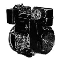
Lombardini 11 LD 626-3 Use And Maintenance (144 pages)
Brand:
Lombardini
| Category:
Engine
| Size: 3.73 MB
Table of Contents
Indice Riassuntivo Delle Operazioni DI Prima Manutenzione
3
Index Récapitulatif des Opérations de Premier Entretien
3
Summary of First Maintenance Operations
3
Inhaltsverzeichnis der Ersten Wartungsarbeiten
3
Indice Compendioso de las Operaciones de Manutencion
3
Indice Resumidor das Operações de Primeira Manutenção
3
Table of Contents
8
Identificazione Motore - Identification Moteur - Engine Type - Identifizierungsdaten - Identificacion del Motor - Identificação Do Motor
12
Premessa/Clausola DI Garanzia
15
General Service Manual Notes
18
Preface/Warranty Certificate
19
Premisa/Clausula de Garantia
23
Preâmbulo/Certificado de Garantia
25
Παρατηρησειε Και Προειαοποιησεισ
38
Ο∆Ηγιεσ Ασφαλειασ
38
Waarschuwings Tekens - Veiligheidsvoorschriften
40
Caratteristiche - Caracteristiques - Characteristics - Technische Daten - Caracteristicas - Características
48
DIMENSIONI D'INGOMBRO - MESURES D'ENCOMBREMENT OVERALL DIMENSION - Einbaumaße DIMENSIONE EXTERIORES - DIMENÇÔES EXTERIORES
49
Prima Dell'avviamento - Avant Le Demarrage before Starting - vor dem Anlassen Antes del Arranque - Antes Do Aviamento
51
Uso - Emploi - Use - Bedienung - Utilisacion - Utilização
52
Specifiche Internazionali Per I Lubrificanti
56
Spécifications Internationales Pour Les Lubrifiants
56
Lubricant International Specifications
56
Internationale Spezifikationen für Schmiermittel
57
Especificaciones Internacionales para Lubricantes
57
Especificações Internacionais para os Lubrificantes
57
Sequenze Api / Mil - Sequences Api / Mil - Api / Mil Sequences
59
Api / Mil-Sequenzen - Secuencias Api / Mil - Sequências Api / Mil
59
Capacidad Aceite Motores
60
Capacitá Olio Motori
60
Fill Engine with Oil - Öl-Aufüllen
62
Suministración Aceite Motor Reabastecimento Óleo Motor
62
Disareazione - Deareation - Air Bleeding - Entlüftung
72
Purgado del Circuito de Inyeccion - Disarejação
72
Avviamento - Demarrage - Starting - Anlassen Arranque - Aviamento
74
Avviamento Elettrico - Démarrage Électrique - Electric Starting Elektroanlass - Arranque Eléctrico - Aviamento Electrico
74
Descrizione Delle Spie - Description des Voyants - Indicators Descritpion
76
Beschreibung der Kontrolllampen - Descripción de Los Testigos
76
Avviamento Recoil- Démarrage Recoil - Recoil Starting System Seilstart - Arranque Recoil - Aviamento Recoil
78
Dopo L'avviamento - Apres Le Demarrage after Starting - nach dem Anlassen Despues del Arranque - Depois Do Aviamento
80
Rodaggio - Rodage - Run-In - Einlaufen - Rodaje - Rodagem
80
Prima Dell'arresto - Avant L'arret - before Stopping vor dem Abstellen - Antes del Paro - Antes da Parada
80
Arresto - Arret - Stopping - Abstellen - Paro - Parada
80
Turning off Engines - Ausschalten von Motoren Apagado Motores - Paragem de Motores
81
Manutenzione - Entretien - Maintenance Wartung - Manutencion - Manuntenação
82
Betriebsstunden - Después de las Primeras 50 Horas Após as Primeiras 50 Horas
83
Após as Primeiras 50 Horas
83
Alle 250 Stunden - cada 250 Horas - cada 250 Horas
88
Alle 500 Stunden - cada 500 Horas - cada 500 Horas
98
Anlagen - Instalaciones - Circuitos
108
Baterias Recomendadas
109
1) Alternatore Interno - Alternateur Interieur - Internal Built-In Alternator - Innerer Generator - Alternador Interno - Alternador Interno
110
3) Circuito Combustibile - Circuit de Graissage - Fuel System - Kraftstoffanlage - Circuito Combustibile - Circuito Combustivel
112
Schema Elettrico Dispositivo Elettrostop - Schéma Électrique Dispositif Stop Électrique - Diagram of Stop Solenoid - Schaltplan der Einrichtung Elektrostop - Esquema Eléctrico del Dispositivo Electrostop - Esquema Eléctrico Do Dispositivo Eléctrico de Par
113
Circuito Lubrificazione - Circuit de Graissage - Lubricating System - Schmierölkreislauf - Circuito de Lubrificación - Circuito Lubrifiação
114
Esquema Eléctrico Completo de Cablagem Do Motor
115
Head Temperature Thermostat - Thermostat Kopftemperatur - Termostato Temperatura Culata - Termóstato para Temperatura Do Cabeçote
116
E-Teil Bestellungen - Pedidos de Repuestos Pedidos Recâmbios
127
Garantieschein - Tarjeta de Garantia - Boletim de Garantia
140
Advertisement
Advertisement
Related Products
Lombardini 9 LD 625-2 EPA
Lombardini 9 LD 626-2
Lombardini 9 LD 626-2 NR
Lombardini 4 LD 640
Lombardini 4 LD 640/L
Lombardini 11 LD 625-3
Lombardini 9 LD 625-2
Lombardini 9 LD 561-2
Lombardini 15 LD 440
Lombardini LDA672
Lombardini Categories
Engine
Air Conditioner
Controller
More Lombardini Manuals
Login
Sign In
OR
Sign in with Facebook
Sign in with Google
Upload manual
Upload from disk
Upload from URL