Sign In
Upload
Manuals
Brands
Leica Manuals
Laboratory Equipment
TCS SP8 SMD
Leica TCS SP8 SMD Manuals
Manuals and User Guides for Leica TCS SP8 SMD. We have
1
Leica TCS SP8 SMD manual available for free PDF download: User Manual
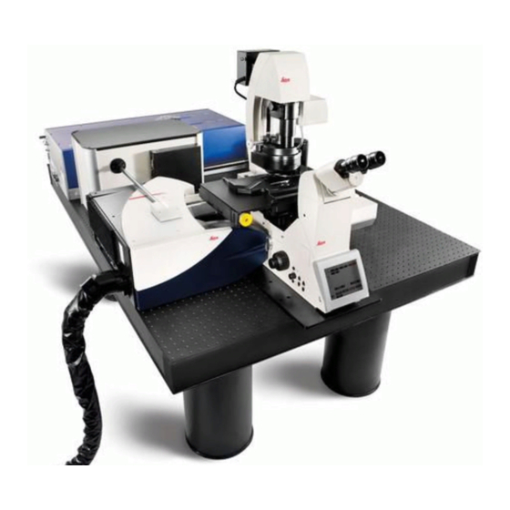
Leica TCS SP8 SMD User Manual (270 pages)
for FCS, FLIM and FLCS
Brand:
Leica
| Category:
Laboratory Equipment
| Size: 3.31 MB
Table of Contents
Copyright
3
Table of Contents
5
Contents
5
1 About this User Manual
15
Additional Documentation
16
2 Intended Use
17
3 Liability and Warranty
19
Important Information for Operators and Users
19
4 Meaning of the Warning Messages in the Manual
21
5 General Safety Notes
23
Commissioning and Use
23
Modifications to the System
24
Safety Devices and Safety Labels
24
Laser Safety
24
Electrical Safety
26
Contact with Liquids
26
Malfunction of the System
26
6 Additional Notes on Handling the System
29
Location
29
Using the Software
29
Protecting the System
30
Objectives
31
7 System Overview and Properties
33
TCS SP8 SMD System Variants
33
TCS SP8 SMD System Components
33
TCS SP8 SMD with Upright Microscope
34
TCS SP8 SMD with Inverted Microscope
34
TCS SP8 SMD System Variants with White Light Laser
35
TCS SP8 SMD System Components with White Light Laser
35
TCS SP8 SMD with White Light Laser and Upright Microscope
36
TCS SP8 SMD with White Light Laser and Inverted Microscope
37
TCS SP8 SMD System Variants with MP Configuration
38
Controls on the Supply Unit
40
Main Switch Board on the Flexible Supply Unit
40
Control Panel Field on the Compact Supply Unit (Only for FLIM)
40
Technical Data
41
Dimensions
41
Weight
41
Electrical Specifications
42
Electromagnetic Compatibility
42
Serial Number
43
8 Ambient Conditions
45
General Requirements Regarding Ambient Conditions
45
Vibrations
45
Room Dimensions
46
Electrical Connection Requirements
47
System with Flexible Supply Unit
47
System with Compact Supply Unit (Only with FLIM)
48
External Lasers
48
Load Capacity of the Multiple Socket Outlet on the Flexible Supply Unit
49
Waste Heat and Cooling
49
System with Flexible Supply Unit
50
System with Compact Supply Unit (Only with FLIM)
50
External Lasers
50
9 SMD Components
51
Hardware Components and Software Licenses
51
FCS/FCCS Application Area
51
Special SMD Hardware
51
Software License
51
FLIM Application Area
52
Special SMD Hardware
52
Software License
52
Application Area FCS/FCCS, FLIM, FLCS, Gated FCS
53
Special SMD Hardware
53
Software License
53
Beam Path
53
Detection Units from Picoquant
54
Leica APD Detector Unit
55
General Precautionary Measures for Using APD Detector Units
56
Changing the Fuse
56
Safety Shutoff
56
Trigger Unit
56
Laser Coupling Unit (LCU)
57
Attenuation Unit
58
Other Picoquant Components
59
10 Laser
61
Laser Classes
61
Overview of Usable Lasers for Image Acquisition
61
VIS/UV Lasers for TCS SP8
61
VIS/UV Lasers for TCS SP8 X
62
IR Lasers for TCS SP8 MP
62
Picosecond Laser
62
Femtosecond Laser
63
Overview of Usable Lasers for FCS
63
VIS/UV Lasers for TCS SP8 SMD
63
Overview of Usable Lasers for FLIM
64
VIS/UV Lasers for TCS SP8 SMD
64
Infrared Lasers for TCS SP8 SMD with MP Configuration
64
Picosecond Laser
64
Femtosecond Laser
64
Overview of Usable Lasers for FLCS
66
VIS/UV Lasers for TCS SP8 SMD
66
11 Safety Features
67
Main Circuit Breaker for Disconnecting the Power Supply
67
Compact Supply Unit
67
Flexible Supply Unit
67
Other Components
68
Key Switch
68
Master Key Switch on the Compact Supply Unit
68
Master Key Switch on the Flexible Supply Unit
68
Key Switch for the White Light Laser
69
Key Switch for UV Lasers
69
Key Switches for Other External Lasers
70
Emission Warning Indicators
70
Emission Warning Indicator on the Supply Unit
70
Emission Warning Indicator on the White Light Laser
71
Emission Warning Indicator on UV Lasers
71
Emission Warning Indicator on Other External Lasers
72
Malfunction of Emission Warning Indicator
72
Interlock Connectors
72
Interlock Connector on the Supply Unit
72
Interlock Connector on the White Light Laser
74
Interlock Connector on Other External Lasers
74
Interlock Connector on the Scan Head
75
Safety Switches on the Microscope
76
Warning Messages
76
Special Laser Safety Equipment
78
Laser Protection Tube and Laser Protection Shield
78
Safety Beam Guide on the MP System
79
12 Safety Labels on the System
81
Compact Supply Unit (Only for FLIM)
81
Flexible Supply Unit
82
Inverted Microscope
83
Upright Microscope
84
Mirror Housing
85
Cover for Replacement Flange
86
Transmitted Light Detector (Tld)/Reflected Light Detector (RLD)
87
Scan Head
87
White Light Laser
89
External UV Laser
89
MP Beam Coupling Unit
90
Other External Lasers
90
13 Switching on the System
91
Confocal System with Flexible Supply Unit
91
Confocal System with Compact Supply Unit (Only with FLIM)
96
Hyd Reflected Light Detectors (Hyd Rlds)
99
Starting the SMD Hardware and Software
100
14 Las Af
103
Starting las AF
103
Structure of the Graphical User Interface
104
Design of the FLIM Wizard in las AF
107
Design of the FCS Wizard in las AF
110
LAS AF Online Help
113
Structure of Online Help
113
Accessing Online Help
113
Selecting the Language for Online Help
113
Using Online Help
114
Full-Text Search with Logically Connected Search Terms
115
15 Selecting the Laser
117
Activate Laser as the Excitation Source in the Configuration Menu
117
Using Continuous Wave VIS Lasers
118
Using MP Lasers
119
Using Pulsed VIS Lasers
121
Using Pulsed UV Lasers
124
Using a Pulsed White Light Laser
124
16 FLIM Data Acquisition
127
Setup Imaging Step - Image Acquisition
127
Selecting Detectors for the Image Acquisition
127
Internal Photomultipliers (Including SP FLIM PMT)
127
External Apds
129
External FLIM Photomultiplier
130
Selecting Laser Lines as an Excitation Source for Image Acquisition
130
Using Continuous Wave Lasers
130
Using MP Lasers
131
Using Pulsed VIS Lasers
131
Using Pulsed UV Lasers
132
Using White Light Lasers
133
Adjusting the Pinhole for Image Acquisition
133
Setup FLIM Step - Optimizing the FLIM Measurement Conditions
134
Selecting FLIM Detectors
134
FLIM Data Acquisition with Internal SP FLIM Detectors
135
FLIM Data Acquisition with External MPD Apds
136
FLIM Data Acquisition with External Photomultiplier
137
FLIM Data Acquisition with Detectors at NDD Position (Hyd RLD)
138
Selecting Laser Lines for FLIM
140
Do Not Use Continuous Wave VIS Lasers
140
Using Pulsed Diode Lasers (UV, VIS)
141
Using MP Lasers
141
Using White Light Lasers
142
Adjusting the Fluorifier Disc
142
Setting for SP FLIM
142
Setting for External FLIM or Intensity Image Acquisition
144
Setting for FLIM White Light Laser
144
Changing the Pulse Frequency for Pulsed Diode Lasers
145
(405, 440, 470, 640 Nm)
145
2-Laser PIE (405, 470, 640 Nm)
146
Changing Pulse Frequency for White Light Lasers
147
Setting the Pinhole
148
Optimizing FLIM Settings
148
Count Rate Monitor
149
Loading and Saving FLIM-Specific Instrument Parameter Settings
149
Measurements Step - Time Series for FLIM Measurement
150
At Multiple Points
150
FLIM Network Connection
150
Definition of the FLIM Measurement File Names Transferred to
150
Symphotime
150
Defining a Single FLIM Image
152
Defining an Xyz or Xzy FLIM Stack
153
Defining an FLIM Time Series
154
Defining a Time Series of Xyz or Xzy FLIM Stacks
155
Defining an Xy or Xz FLIM Stack
157
Defining a Time Series of Xy or Xz FLIM Stacks
158
Defining an Xy or Xz FLIM Stack
160
Control of FLIM Measurements
162
17 Summarized Manual for FLIM Experiments
163
Prerequisites
163
Selecting Position for the FLIM Measurement
163
Changing from Continuous to Pulsed Excitation
163
Changing from Internal Detection on the SP8 to External TCSPC Detectors
164
Using Internal SP FLIM Detection
164
Using FLIM Detectors at the NDD Position (Hyd RLD)
164
Setting Suitable Scan Parameters
165
Optimizing the Photon Count Rate
165
Selecting the Correct Laser Repetition Rate
168
Starting FLIM Data Acquisition
170
Resulting Raw Data File and Documentation
170
Measuring the Instrument Response Function (IRF)
172
Preparing IRF Measurements
172
Estimating the IRF
172
With Reflection Mode
172
With Fluorescence Mode
173
With SHG
173
Running IRF Measurement
174
Remarks
176
Ad-Hoc-Inspection of a Specimen
176
Bidirectional Scanning
176
Setting the Laser Intensity of the Diode Lasers
176
Sensitivity of the Fluorescence Detection
176
Optimum Lifetime Information
176
18 L)CS Data Acquisition
177
Preparing the FCS Measurement
177
Selecting an Objective
177
Calibrating the Positioning Accuracy of the FCS Measuring Point
177
Testing the Positioning Accuracy
181
Adjusting the Correction Ring on the Objective
183
Setting the Reference Position
186
Acquiring a Reference Image
186
Image Acquisition Using Photomultipliers
187
Image Acquisition with PE Apds (AQR Type) or MPD Apds
188
(PDM Type)
188
Setup Imaging Step - Image Acquisition
190
Selecting Detectors for the Image Acquisition
190
Photomultiplier (PMT) / Internal Hybrid Detector (Hyd)
190
PE / MPD Apds
190
Selecting Laser Lines as an Excitation Source for the Image Acquisition
191
Using Continuous Wave Lasers
191
Using MP Lasers
192
Using Pulsed VIS Lasers
192
Using a Pulsed UV Laser
193
Using White Light Lasers
194
Adjusting the Pinhole for Image Acquisition
194
Setup FCS Step - Optimizing FCS Measurement Conditions
195
Selecting Apds
195
Selecting Laser Lines for FCS
195
Using Continuous Wave VIS Lasers
195
Using Pulsed VIS Diode Lasers
196
Using White Light Lasers
197
Fluorifier Disc
197
Setting the Pinhole
197
Optimizing FCS Settings
198
Count Rate Monitor
199
Loading and Saving FCS-Specific Instrument Parameter Settings
200
Measurements Step - FCS Measurement Time Series at Multiple Points
201
FCS Network Connection
201
Definition of Multiple FCS Measuring Points in an Image or Stack
202
FCS Time Series at Multiple Measuring Points
204
Definition of the File Names Transferred to Symphotime During the FCS Measurement
206
FCS Z-Stack
207
Operating the FCS Measurement Series
208
19 Summarized Manual for FCS or Other Point Measurements
209
Prerequisites
209
Choosing the Location for the FCS Measurement
209
Starting Point/ FCS Data Acquisition
210
20 Changing the Specimen
213
Changing the Specimen on an Upright Microscope
213
Changing the Specimen on an Inverted Microscope
213
21 Changing the Objective
215
22 Piezo Focus on Upright Microscope
217
23 Changing the Filter Cube
219
24 Changing Detector Cable Connections on the Scan Head and Router When
221
Using Hyd-RLD
221
Hardware Trees
222
MP on FCS FLIM 2 APD
223
MP off FCS FLIM 2 APD
223
MP on Hyd RLD FLIM
223
Connect and Use Detectors
224
Using SP FLIM PMT
224
Using MPD Apds
224
Using Hyd-RLD
225
25 Switching off the System
229
System with Flexible Supply Unit
229
System with Compact Supply Unit (Only for FLIM)
233
26 Care and Cleaning
239
Cleaning Surfaces
239
Cleaning the Optical System
239
Cleaning Immersion Lenses
240
Care
240
27 Repairs and Service Work
241
28 Maintenance
243
Having Coolant Replaced
243
29 Disassembly and Transport
245
30 Disposal
247
31 Troubleshooting
249
Hardware Configuration Gets Lost or Software Needs to be Installed Again
249
The Instrument Is Losing Sensitivity
249
Causes for Decreased Performance
250
No FLIM Image Is Displayed During Measurement
250
How to Handle PQ Error Codes in las AF
252
32 Contact
253
33 Recommended Literature
255
34 Abbreviations
257
35 Appendix
259
Patents
259
Safety Data Sheets from Third-Party Manufacturers
259
Compliance
265
People's Republic of China
267
Advertisement
Advertisement
Related Products
Leica TCS SP8 X
Leica TCS SP8 FSU
LEICA EM TIC 3X
Leica THERMOBRITE ELITE
Leica TCS SP5 X
Leica TCS SP8 MP
Leica TCS SP8
Leica TCS SPE
Leica TCS SP
Leica TC805
Leica Categories
Digital Camera
Microscope
Measuring Instruments
Laboratory Equipment
Binoculars
More Leica Manuals
Login
Sign In
OR
Sign in with Facebook
Sign in with Google
Upload manual
Upload from disk
Upload from URL