Sign In
Upload
Manuals
Brands
Kubota Manuals
Excavators
KX61-3
Kubota KX61-3 Manuals
Manuals and User Guides for Kubota KX61-3. We have
2
Kubota KX61-3 manuals available for free PDF download: Operating Instructions Manual, Workshop Manual
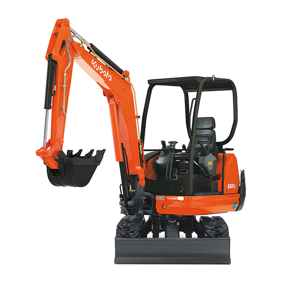
Kubota KX61-3 Operating Instructions Manual (138 pages)
Mini Excavator
Brand:
Kubota
| Category:
Compact Excavator
| Size: 5.81 MB
Table of Contents
Table of Contents
3
Abbreviations
8
General Symbols
9
General Information
10
Foreword
10
EC Declaration of Conformity
10
Date of Issue of the Operating Instructions
11
Operating Personnel
11
Location of the Operating Instructions
11
Spare Parts
11
Safety Rules
12
Basic Safety Instructions
12
Duties, Liability and Warranty
12
Safety Symbols
14
Approved Use
15
Unapproved Use
15
Special Duties of the Owner
15
Noise Emission and Vibration
16
Noise Emission
16
Vibrations
16
Safety Labels on the Excavator
17
Safety Devices
24
Locking the Controls
24
Engine Stop Knob
24
Roll-Over Protection (ROPS)
25
Emergency Hammer
25
Hazards Coming from the Hydraulic System
25
Fire Protection
26
Recovery, Loading and Transport
27
Safety Rules for Recovery
27
Safety Rules for Hoisting the Excavator with a Crane
27
Safety Rules for Transport
27
Recovery
28
Hoisting the Excavator with a Crane
28
Transport on a Flat Bed Trailer
30
Description of the Excavator
32
Model Overview
32
Model KX61-3
32
Model KX71-3
32
Dimensions
33
KX61-3 Dimensions
33
KX71-3 Dimensions
34
Specifications
35
Identification of the Excavator
36
Equipment
36
Standard Equipment
36
Assembly and Functions
37
Component Overview
37
Operator's Place
38
Right Control Console
38
Description of the Components of the Right Control Console
39
Displays and Indicators - Description
39
Left Control Console
40
Description of the Components of the Left Control Console
40
Controls
40
Description of the Controls
41
Further Components in the Cab
42
Fuse Box
42
Interior Lighting
42
Wiper/Washer System
42
Fuel Tank Filler Opening
43
Tool Compartment
43
Vehicle Battery
43
Engine Compartment
44
Hydraulic System
45
Operation
46
Safety Rules for Operation
46
Safety for Children
47
Guiding the Operator
47
Working in the Vicinity of Overhead Power Lines
48
Working in the Vicinity of Underground Power Lines
48
Initial Operation
49
Setting the Display Language
49
Running-In of the Excavator
49
Special Maintenance Instructions
49
Operating the Excavator
49
Pre-Operational Services
49
Check the Engine Oil Level
50
Checking the Coolant Level
50
Checking the Radiator and the Oil Cooler
50
Checking the Exhaust System for Leaks
51
Checking the Oil Level of the Hydraulic System
51
Checking the V-Belt
51
Checking the Water Separator of the Fuel System
52
Lubrication
52
Checking the Fuel Level of the Fuel Tank
53
Setting up the Workplace
53
Adjusting the Operator's Seat
54
Getting on the Excavator
54
Horizontal Seat Adjustment (Seat Stand-Off)
54
Seat Height Adjustment (Knee Height)
54
Spring Adjustment (Operator's Weight)
54
Backrest Adjustment
55
Exterior Mirror Adjustment
55
Seat Belt
55
Safety Instructions for Starting the Engine
55
Starting the Engine
56
Stopping the Engine
57
Observation of the Displays after Starting and During Operation
57
Driving the Excavator
58
Driving
59
During Driving
60
Turning
60
Driving Uphill and Downhill
61
From a Standing Position
61
Turning on the Spot
61
Making Sharp Turns
62
Notes for Rubber Crawler Operation
62
Protecting the Crawler against Salt
62
Operating the Controls During Excavation Work
62
Notes for Using Wider and Deeper Buckets
63
Operating the Dozer Blade
63
Operating the Boom
64
Overview of Control Lever Functions
64
Operating the Arm
65
Operating the Bucket
66
Swivelling the Swivel Frame
66
Swinging the Boom
67
Operating the Auxiliary Port
68
Pressure Relief of the Hydraulic System
69
Return Change Valve
69
Placing out of Operation
70
Cab Version Only
70
Operating the Wiper/Washer System
71
Switching on the Windscreen Wiper
71
Switching on the Washer System
71
Operating the Room Light (Cab Version)
72
Operating the Rotary Beacon (Accessories)
72
Operating the Heater (Cab Version)
72
Opening and Closing the Cab Door
74
Opening the Cab Door from Outside
74
Closing the Cab Door
74
Opening the Cab Door from Inside
74
Opening and Closing the Windows
75
Front Window
75
Side Window
76
Operating the Working Lights
76
Cold Weather Operation
77
Necessary Preparations Prior to the Winter Season
77
Operation During the Winter Season
77
Jump-Starting the Excavator
78
Emergency Stop Functions
79
Manual Engine Stop
79
Manual Lowering of the Front Attachments
79
Filling up the Washer System
79
Refuelling the Excavator
80
Bleeding the Fuel System
80
Replacing the Fuses
81
Fuse Layout of the Fuse Box
82
Installing and Uninstalling the Operator's Seat
82
Opening and Closing the Engine Compartment Cover
82
Opening and Closing the Side Cover
83
Removing and Installing the Right Side Panel
83
Replacing the Bucket
84
Anti-Theft System
84
Black (Individual) Key
85
Red Key (for Registering)
85
The Key System
85
Registering a Black Key for the Machine
86
Troubleshooting
88
Safety Rules for Troubleshooting
88
Troubleshooting: Pre-Operational Services
88
Troubleshooting: Operation
89
Troubleshooting: Display Indications
90
Maintenance
91
Safety Rules for Maintenance
91
Personnel Requirements
91
General Maintenance Chart: 50 to 500 Hours of Operation
92
General Maintenance Chart: 550 to 1000 Hours of Operation
93
Servicing Maintenance Chart: 50 to 500 Hours of Operation
94
Servicing Maintenance Chart: 550 to 1000 Hours of Operation
95
Cleaning the Excavator
96
Maintenance
96
Refilling the Coolant
96
Cleaning the Radiator
97
Checking and Adjusting the V-Belt Tension
97
Checking the Coolant Hoses
98
Replacing the Engine Oil and Oil Filter
98
Draining the Engine Oil
98
Filling the Engine Oil
99
Replacing the Oil Filter
99
Replacing the Coolant
100
Checking and Cleaning the Air Filter
101
Replacing the Fuel Filter
102
Draining Water from the Fuel Tank
103
Replacing the Return Filter in the Hydraulic Oil Tank
103
Replacing the Suction Filter in the Hydraulic Oil Tank
104
Draining and Topping up Hydraulic Oil
105
Draining the Hydraulic Oil
105
Filling the Hydraulic Oil
106
Replacing the Breather Filter in the Hydraulic Oil Tank
106
Battery Service
107
Checking the Fluid Level of the Battery
107
Charging the Battery
108
Installing/Uninstalling and Replacing the Battery
109
Lubrication
109
Greasing the Swivel Gear
109
Greasing the Pitch Bearing
110
Checking and Tensioning the Crawler Tension
110
Adjusting the Crawler Tension
111
Checking the Crawler Tension
111
Replace the Drive Unit Oil
112
Greasing the Pilot Valve Linkage
112
Checking the Electric Cables and Connections
112
Replacing the In-Line Filter
113
Resetting the Service Period Indicator
113
Checking the Bolted Joints
114
Tightening Torque for Screws
114
Tightening Torque for Hose Clamps
114
Tightening Torque for Hydraulic Hoses
114
Tightening Torque for Hydraulic Pipes
115
Tightening Torque for Hydraulic Adapters
115
Recommended Lubricants
116
Repair Work on the Machine
117
Safety Inspection
118
Taking out of Service and Storage
119
Safety Rules for Taking out of Service and Storage
119
Storage Conditions
119
Measures before Taking out of Service
119
Measures During Taking out of Service
119
Start-Up after Taking out of Service
120
Lifting Capacity of the Excavator
121
Constructive Calculation of Lifting Capacity
121
Lifting Attachment
122
Load Suspension Device
123
Max. Lifting Load During Swivel Operation Is 360
124
Accessories
134
KUBOTA Rotary Beacon
134
KUBOTA Arms
134
KUBOTA Pipe Safety Valve
135
Note on the Use
135
KUBOTA Overload Warning Function
136
KUBOTA Quick Coupling Systems and Equipments
136
KUBOTA Bucket Accessories
136
Advertisement
Kubota KX61-3 Workshop Manual (137 pages)
Brand:
Kubota
| Category:
Excavators
| Size: 5.83 MB
Table of Contents
Inch
2
Contents
3
Table of Contents
4
Kx61-3, Kx71-3 Wsm-M
5
General
5
Sales Feature
5
Difference between KX61-3 and KX71-3
5
Quick Chart for Selling Points : KX61-3, KX71-3
6
Comparison to Competitors; EU - Version
7
Compornents Compatibility
8
Machine Specifications
9
Machine Weight
10
Quality Specifications
11
Inch
17
Inch
18
Inch
20
Inch
21
KX71-3 PP - Version
24
Machine Body
24
Main Component
24
Pump Coupling
24
Bucket: Kubota Standard Bucket
25
Kx-61-3
25
Kx-71-3
25
Bucket Dimensions
26
Boom, Arm, Bucket Link
27
Bucket Installation Relevant Dimensions
27
Bushing
28
Swing Bracket
29
Swivel Bearing
30
Idler and Tension Spring: Rubber Track and Iron Track
31
Structure
31
Track Roller
32
Rubber Track
33
Iron Track
34
Iron Track - Rubber Track
35
Rubber Track - Iron Track
35
Track Conversion
35
Track Tension Adjustment
35
Inspection of Hydraulic Oil
36
Water and Oil Quantity
36
Engine
38
Engine Electric Components
38
Engine Specifications
38
Performance Curve: KX61-3 EU, V1505-E2-BH-9-EU
39
Performance Curve: KX71-3 EU, V1505-E2-BH-10 EU
40
Performance Curve: KX71-3 PP, V1505-E2-BH-10
41
Hydraulic Circuit Diagram
44
Hydraulic System Feature
44
Main Pump
44
KX61-3: EU - Version
45
KX71-3: EU - Version
46
KX71-3: PP - Version
47
Hydraulic Components ; KX71-PP-Version
48
Main Pump
49
Outer View
49
P-Q Performance Curve
51
Pump Specifications, Type : PVD-1B-28P-8G3-4575A
51
Control Valve Assy
53
KX61-3: EU - Version, Code No:rg248-61131, Maker: Hydro Control
53
KX71-3: EU - Version, Code No:rg448-61131, Maker: Hydro Control
54
KX71-3: PP - Version, Code No:rc348-61131, Maker: NABCO
55
A-A: Swivel Section
56
B-B : Dozer Section
56
Control Valve Section: KX71-3 PP - Version (RB448-61131)
56
E-E: Service Section
57
F-F: Arm Section
57
G-G: Travel R Section
57
H-H: Inlet Section
58
I-I: Travel R Section
58
J-J: Boom Section
58
K-K: Boom Lock Valve
59
L-L: Bucket Section
59
N-N: Book Lock
59
EU - Version
60
Pilot Valve
60
KTC, KCL, KTA-Version
61
Structure & Specifications
61
Tightening Torque List
61
Specifications
62
Pilot Valve Control Diagram
63
Km/H
64
Technical Data: Travel Motor
64
EU - Version; Maker: Transmital Bonfiglioli
65
Travel Motor
65
KX71-3 PP-Version
66
Motor Rotating Direction
66
(KX71-3 PP-Version)
67
Circuit Diagram (KX61-3, 71-3 EU-Version)
67
Swivel Motior
68
Technical Data
68
Direction of Rotation (View from Pinion Shaft)
69
Outer View
69
Inner Parts
70
Sectional View (KX61-3, 71-3 Swivel Motor Assy)
73
Cylinder
75
Major Size
75
Rotary Joint
76
Accessories of Hydraulic Components
77
Unload Valve (Change Valve): North America and Oceanea - Version
77
Change Valve with Accumulator: EU Version
78
Structure Maker: Hydro Control
78
TPSS Valve (Two Pattern Selection System)
79
Oil Cooler
80
Pilot Filter
81
Specifications (RB411-62151)
82
Suction Filter
82
Return Filter
83
Specifications (RB411-62191)
83
Check Valve
84
Main Relief Valve (at the Measurement Port on the Machine)
85
Maintenance Specification
85
Overload Relief Valve (at the Measurment Port on the Machine)
85
Cylinder Natural Fall Amount
86
Cylinder Operating Speed
86
Background of Adoption of New Meter
88
Development Concept
88
Electrical System
88
Features of New Meter
88
Electrical System: Functional Comparison: KX61-3, KX71-3
90
Outline of Kubota ICS (Intelligent Control System)
91
Operating Mode
94
Outline
94
LCD Display List
95
Service Mode Flow Chart
98
Service Mode Menues
98
Main Menues and Functions
99
Selection Method of 11 Languages
99
Service Mode Language Selection Screen
99
Calculation Method
100
Tester Mode
100
Deletion of Fail Record
101
Fail Recoord Dump
101
Machine Model Setup
102
Overheat Set-Up
102
Harness Check Mode
103
Simple Mode Set-Up --- Chinese-Version Only
103
All Fail Record
104
EEPROM Read
104
LCD Inspection
104
Servive Hour Meter Check
105
Servive Hour Meter Delete
105
Set-Up Time
105
Software Version
105
Auto Glow Control
106
Cooling Water Temperature Vs. Glow Time
106
Graph of Water Temperature Vs. Glow Time
106
Key-ON Processing
106
Glow Control (Others)
107
Glow ON/OFF Conditions
107
Refreshment Cycle of Number of Dots
107
Relationship between Water Temperature and Dots
107
FYI (for Your Information)
108
Travel High - Low Switch Control
109
Circuit Diagram & Function (Fuel Sensor)
110
Fuel Amount Control
110
Fuel Shortage Alarm
110
Voltage and Fuel Map
110
Meter Display
111
Fuel Replenishment Assist Function
112
Startor Auto Release Control
113
Auto Release Circuit Diagram & Function
114
Trouble Shooting
115
Operational Flow Chart
116
KX41-3 Service Hour Meter with North American Specifications
119
Service Hour Meter
119
Failure Diagnosis
120
Failure Display and Diagnosis Criteria
120
Error Storage Method
122
Fail Record in EEPROM
122
Number of Errors
122
To 15.7
122
Address and Contents of EEPROM
123
Erasing Method of Error Log
123
Operation Procedure
125
Purpose
125
Self-Diagnosis of Controller Unit
125
Failure Display Number of Self-Diagnostic Function
127
Self - Diagnosis of Controller, Items and Methods
127
Check Sum Error
129
Functions of Self-Diagnostic Harness
130
Electrical Component Layout
131
Service Mode KX61-3, KX71-3(Non-AI Non- Anti-Theft Non-S/O) Ver 1.13
132
Circuit Wiring Diagram
133
KX61-3, KX71-3 Export (EU) (US)
133
KX61-3, KX71-3 Export Standard Type
134
Advertisement
Related Products
Kubota KX 016-4
Kubota KX91-3a
Kubota KX121-3a
Kubota KX161-3a
Kubota KX101-3a
Kubota KX91-3S
Kubota KX121-3S
Kubota KX080-4
Kubota KX91-3a2
Kubota KX101-3a2
Kubota Categories
Tractor
Lawn Mower
Engine
Farm Equipment
Excavators
More Kubota Manuals
Login
Sign In
OR
Sign in with Facebook
Sign in with Google
Upload manual
Upload from disk
Upload from URL