Sign In
Upload
Manuals
Brands
Kubota Manuals
Excavators
KX161-3a
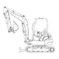
User Manuals: Kubota KX161-3a Construction Equipment
Manuals and User Guides for Kubota KX161-3a Construction Equipment. We have
1
Kubota KX161-3a Construction Equipment manual available for free PDF download: Workshop Manual
Kubota KX161-3a Workshop Manual (207 pages)
Minor change Chapter
Brand:
Kubota
| Category:
Excavators
| Size: 16.36 MB
Table of Contents
Table of Contents
3
Sales Engineering Section
4
Kx91-3S, Kx91-3 , Kx101-3 , U35S, U35-3S, U35-3
5
I Sales Engineering Section
5
Quick Feature Chart
5
Kx121-3S, Kx121-3 , Kx161-3S, Kx161-3 , U45-3S, U45-3
6
Feature Discriptions (Super Series)
7
New Innovations
9
Main Machine Specifications
10
Specifications: Super Series (KTC, KCL, KTA-Version)
10
Dimensions
11
Lifting Capacity
11
Working Range
11
Service Engineering Section
12
General Outline
13
New Engineering Points
13
Photos of Main Modified Parts
14
Major Specifications Incorporated
15
Quantity Water and Oil
16
Quality Specifications
17
Service Engineering Section
18
KX121-3S, 161-3S: KTC, KCL, KTA Version
25
Machine Specification: Service Port, TPSS, Arm Rest, Long Arm, 4 Postcanopy, KTC-Bucket
25
Finger Control Service Port System
33
Feature and Purpose
33
Aux. Port Finger Operation
34
Control Layout
34
Outline of Control System
34
Service Port System Components
35
Hydraulic Circuit Diagram
36
Knob Structure and Function
37
Structure of Knob Switch
37
Basic Operation of the Knob
38
Flow Chart; Service Port Operation
39
Function Chart
40
S/P Switch (Service Port Switch)
40
Breaker Operation
41
How the Knob Switch Works
41
Interrelation Among Current, Pressure and Flow
42
Initial Settings of the Knob
43
Knob Shift Amount and Output Voltage
43
Purpose
43
Set-Up and Adjustment of Service Port
43
Background and Meaning of Knob Initial Set-Up
44
FYI (for Your Information)
44
Performance Characteristics Profile: Knob Shift Amount Vs Output Current
45
S/P Valve Start Point Setting
45
Background and Meaning of Start-Point Setting
47
Illustration of the Start-Point Setting
48
Concrete Behavior at the Start-Point Setting
49
S/P Valve Initial Set-Up Flow Chart
50
Manual Feeling Setting
51
Outline of Manual Feeling Setting
51
Knob Shift Amount and Output Current
52
Outline (S/P Knob, S/P Valve, S/P Feeling Adjust)
53
Panel Display Operation Flow Chart
53
Display Flow Chart with Photo
54
Knob Initial Set-Up
57
S/P Valve Initial Set-Up
58
S/P Operational Feeling Adjustment
60
Outline
62
Proportional Control Solenoid Valve (S/P Valve)
62
Hydraulic Symbols
63
Structure and Function
63
Behavior of Proportional Valve
64
Function Theory
64
Spool Control Performance I-P Curve
65
Spool Opening Area
65
Automatic Service Port Identification
66
Compressor Control
66
Model Number Display
66
Other Controls
66
Troubleshooting
67
Control Valve: KX121-3S , 161-3S , U45-3
69
Hydraulic Pump: KX121-3S , 161-3S , U45-3
69
Outline
69
Travel Motor: KX121-3S , 161-3S , U45-3
69
Hydraulic Pump: KX161-3S, KX161-3
70
Hydraulic System Modification
69
Pump Installation: KX161-3S, U45-3
70
Piston Pump Power Constant Characteristics
73
Specifications of Pump
73
Control Valve
75
PP-Version (KX161-3S)
75
EU, KTA-Version (KX161-3Αs)
76
Third Line-Version: EU & KTA, KX161-3Αs
77
Inlet Section; KX121-3Sα, 161-3Sα
78
Other Section, Shuttle Plate Change
79
Accumulator
80
Structure and Specifications: PP-Version
80
Change Valve with Accumulator: EU-Version
81
Specifications
81
Structure Maker: Hydro Control
81
Accumulator Installation: KX91-3S, U35S, U35-3S (KTA)
82
Bolt Tightening Torque
82
Accumulator Installation: KX121-3S, 161-3S
84
Hydraulic System Line
85
Pilot Control Line: PP-Version, KX161-3S
85
Pilot Control Line: EU-Version, KX161-3Α
86
Pilot Delivery Line: KX161-3S
87
Pilot Filter
88
Pilot Control Line: KX91-3S, U35S, U35-3S (KTA)
89
Delivery Hose: KX91-3S, U35S, U35-3S (KTA)
90
Rotary Joint Hoses: KX91-3S, U35S, U35-3S (KTA)
92
Change Valve
93
Service Port (S/P) Solenoid Valve
94
Machine Front
95
S/P Valve
95
Heat-Up Circuit
96
Control Valve
97
Counterbalance Mechanism
97
Improvement of Start-Up and Stop Feeling
97
Market Demand to the Travel Motor
97
Travel Motor: KX91-3S: PP-Version
97
At Motor Stop
98
Brake Pressure Waveform (with Shockless Relief Valve)
98
Conventional Pressure Control Method
98
Better Feeling at Start and Stop
98
Counterbalance Spool and Orifices
99
Improvement of the Counterbalance Spool Performance
99
Spool Stroke and Opening
99
Performance Comparison
100
Travel Motor Minor Change: KX121-3Sα, 161-3Sα, U45-3Sα
101
Motor Change Points
101
Swash Plate and Hi-Low Piston
102
Hydraulic Circuit Diagram
103
KX91-3S: KTC-Version
105
KX91-3S: KCL, KTA-Version
106
KX91-3 : EU-Version
107
KX101-3: EU-Version
108
U35S: KTC-Version
109
U35-3S: KTA-Version, U35S: KCL-Version
110
U35-3: EU-Version
111
KX121-3S: KTC, KCL-Version
112
KX121-3S: KTA-Version
113
KX121-3 : EU-Version
114
KX161-3S: KTC, KCL, KTA-Version
115
KX161-3: EU-Version
116
U45-3S: KTA-Version
117
U45-3: EU-Version
118
Hydraulic Components Layout: KX91-3S , KX101-3S , U35S, U35-3S
119
Hydraulic Components Layout: KX121-3S , KX161-3S
120
Engine Upgrade
121
Engine Specifications
121
General
121
Engine Electric Components
122
Engine Performance Curve
123
Engine Performance of KX161-3 Super Series V2403 Vs V2203
125
Electrical System
126
Background of Adoption of New Meter
127
Development Concept
127
Features of New Meter
127
LCD Display Examples of New Meter
128
Electrical System : Functional Comparison: KX91-3S, 101-3, 121-3S, 161-3S, U35S, U35-3, U45Sα
129
Outline of Kubota ICS (Intelligent Control System)
130
Operating Mode
133
LCD Display List
134
Operating Mode Menu List
134
Caution and Warning Indications
135
Service Mode Flow Chart
136
Service Mode Menues
136
Main Menues and Functions
137
Selection Method of 11 Languages (EU-Version Only)
137
Calculation Method
138
Tester Mode
138
Deletion of Fail Record
139
Fail Recoord Dump
139
Machine Model Setup
140
Overheat Set-Up
141
Simple Mode Set-Up - Chinese-Version Only
141
Harness Check Mode
142
All Fail Record
143
EEPROM Read
143
LCD Inspection
143
Service Hour Meter
144
Service Hour Meter with North American Specifications
144
Servive Hour Meter Check
145
Servive Hour Meter Delete
145
Set-Up Time
145
Software Version
145
Auto Glow Control
146
Cooling Water Temperature Vs. Glow Time
146
Graph of Water Temperature Vs. Glow Time
146
Key-ON Processing
146
Glow Control (Others)
147
Glow ON/OFF Conditions
147
Refreshment Cycle of Number of Dots
147
Relationship between Water Temperature and Dots
147
FYI (for Your Information)
148
Travel High - Low Switch Control
149
Circuit Diagram & Function(Fuel Sensor)
150
Fuel Amount Control
150
Fuel Shortage Alarm
150
Voltage and Fuel Map
150
Meter Display
151
Fuel Replenishment Assist Function
152
Starter Auto Release Control
153
Service Mode Menu List
154
New Auto Idling (AI) Control System
156
Purpose
156
Auto Idle Function Mechanism
156
Trouble Cases
156
Electrical System
156
Interlocked with Anti Theft
157
Interlocked with Lever Lock
157
New Auto Idling Modification
157
AI Function Layout
158
Operating Chart
158
Behavior When the Control Lever Is Returned to Neutral
159
Behavior When the Control Lever Is Operated
160
AI Motor Normal-Turn Circuit
161
AI Motor Reverse-Turn Circuit
162
AI Motor Returning Function
163
Function Chart
163
Function Diagram
164
Idle-Up Control
164
Compressor Control
165
Engine Speed Sensor
167
Governor Sensor
168
Accel Sensor (Electric Accelerator)
169
AI Pressure Switch
170
Function
170
Switch Specifications
170
Auto Release Circuit Diagram & Function
171
Auto Release Function
171
Main Component’s Function
171
If Engine Does Not Start
172
Trouble Shooting
172
Operational Flow Chart
173
Travel Hi-Speed Control Circuit
176
Meter Panel (Controller Unit)
177
Failure Diagnosis
178
Failure Display and Diagnosis Criteria
178
Error Storage Method
180
Fail Record in EEPROM
180
Number of Errors
180
Address and Contents of EEPROM
181
Erasing Method of Error Log
181
Operation Procedure
183
Self-Diagnosis of Controller Unit
183
Failure Display Number of Self-Diagnostic Function
186
Self - Diagnosis of Controller, Items and Methods
186
Check Sum Error
188
Functions of Self-Diagnostic Harness
189
Service Mode Flow Chart
190
What Should You Do in the Following Case?
191
Component Layout
197
KX91-3S, 101-3, U35S, U35-3S Electrical Wirling
197
KX121-3S, KX161-3S Electrical Wiring, A/C
198
KX121-3S, KX161-3S Electrical Wiring, Except A/C
199
Circuit Wiring Diagram
200
Kx91-3S, 101-3, 121-3S, 161-3S, U35S, U35-3S, U45-3S, (S/P, Ai)
200
KX91-3S, U35S, U35-3S: PP - Version
201
KX91-3, 101-3, U35-3: EU - Version
202
KX121-3S, 161-3S, U45-3S: EU and PP - Version
203
Advertisement
Advertisement
Related Products
Kubota KX121-3a
Kubota KX101-3a
Kubota KX121-3S
Kubota KX101-3a2
Kubota KX 016-4
Kubota KX91-3a
Kubota KX91-3S
Kubota KX61-3
Kubota KX080-4
Kubota KX91-3a2
Kubota Categories
Tractor
Lawn Mower
Engine
Farm Equipment
Excavators
More Kubota Manuals
Login
Sign In
OR
Sign in with Facebook
Sign in with Google
Upload manual
Upload from disk
Upload from URL