Sign In
Upload
Manuals
Brands
Komatsu Manuals
Excavators
PC130-7
Komatsu PC130-7 Manuals
Manuals and User Guides for Komatsu PC130-7. We have
3
Komatsu PC130-7 manuals available for free PDF download: Shop Manual, Operation & Maintenance Manual
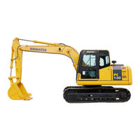
Komatsu PC130-7 Operation & Maintenance Manual (330 pages)
HYDRAULIC EXCAVATOR
Brand:
Komatsu
| Category:
Excavators
| Size: 8.51 MB
Table of Contents
Foreword
5
Safety Information
5
Noise Emission Levels
7
Vibration Levels
7
Guide to Reduce Vibration Levels on Machine
8
Introduction
9
Breaking-In the New Machine
9
Product Information
10
Product Identification Number (Pin)/Machine Serial No. Plate
10
Engine Serial Number Plate and Its Location
10
Service Meter Location
11
Your Machine Serial Numbers and Distributor
11
Machine Serial Number Plate
12
Table of Contents
14
Safety
23
Safety Information
24
Safety Labels
26
Location of Safety Labels
26
Safety Labels
27
Safety Information
35
Safety Rules
35
If Abnormalities Are Found
35
Working Wear and Personal Protective Items
35
Fire Extinguisher and First Aid Kit
35
Safety Equipment
36
Keep Machine Clean
36
Keep Operator's Compartment Clean
36
Leaving Operator's Seat with Lock
36
Handrails and Steps
37
Mounting and Dismounting
38
No Persons on Attachments
38
Burn Prevention
38
Fire Prevention and Explosion Prevention
39
Action if Fire Occurs
40
Windshield Washer Fluid
40
Falling Objects, Flying Objects and Intruding Objects Prevention
40
Attachment Installation
41
Attachment Combinations
41
Cab Widow Glasses
41
Unauthorized Modifications
41
Safety at Jobsite
41
Working on Loose Ground
42
Distance to High Voltage Cables
42
Ensure Good Visibility
43
Ventilation for Enclosed Area
43
Signalman's Signal and Signs
43
Safety Machine Operation
45
Starting Engine
45
Operation
47
Transportation
54
Battery
55
Towing
57
Lifting Objects with Bucket
58
Safety Maintenance Information
60
Operation
67
Machine View Illustrations
68
Overall Machine View
68
Controls and Gauges
69
Detailed Controls and Gauges
70
Monitoring System
70
Basic Check Monitors
71
Caution Monitors
73
Emergency Monitors
75
Meter Display Portion
77
Monitor Switches Portion
80
Switches
83
Control Levers and Pedals
89
Sun Roof
92
Windshield
92
Emergency Exit from Operator's Cab
97
Door Lock
97
Cap with Lock
98
Hot and Cool Box
100
Magazine Box
100
Ashtray
100
Air Conditioner Controls
101
Air Conditioner Control Panel
101
Method of Operation
106
Use Air Conditioner with Care
112
Inspection and Maintenance of Air Conditioner Equipped Machine
112
Other Functions
113
Cab Radio Cassette
114
Controls of Radio Cassette
114
Precautions When Using
114
Auxiliary Electric Power
115
Power Source
115
Fuse
116
Fusible Link
117
Controllers
117
Tool Box
117
Grease Gun Holder
117
Handling Grease Gun
118
Refuelling Pump
119
Accumulator
121
Releasing Hydraulic Pressure with Accumulator
121
Machine Operations and Controls
122
Before Starting Engine
122
Walk-Around Checks
122
Checks before Starting
124
Adjustment
130
Seat Belt
135
Operations before Starting Engine
136
Starting Engine
138
Normal Starting
138
Starting Engine in Cold Weather
140
Ambient Temperature Range for Operation
142
After Starting Engine
142
Warming-Up Operation
142
In Cold Weather Areas
145
Stopping the Engine
149
Machine Operation
150
Preparations for Moving the Machine off
150
Moving Machine Forward
151
Moving Machine Backward
152
Stopping Machine
153
Steering the Machine
154
Steering
154
Swinging
156
Work Equipment Controls and Operations
157
Working Mode
159
Prohibited Operations
160
General Operation Information
162
Traveling on Slopes
163
Escape from Mud
165
Stuck One Side of Track
165
Stuck both Sides of Tracks
165
Recommended Applications
166
Backhoe Work
166
Shovel Work
166
Ditching Work
166
Loading Work
167
Bucket Replacement and Inversion
168
Replacement
168
Inversion
169
Parking Machine
170
Check after Shut off Engine
171
Machine Inspection after Daily Work
172
Locking
172
Overload Warning Device
172
Transportation
173
Transportation Procedure
173
Loading and Unloading with Trailer
174
Loading
175
Securing Machine
177
Unloading
180
Lifting Machine
182
Cold Weather Operation
183
Cold Weather Operation Information
183
Fuel and Lubricants
183
Cooling System Coolant
183
Battery
184
After Daily Work Completion
185
After Cold Weather Season
185
Long Term Storage
186
Before Storage
186
During Storage
186
After Storage
187
Starting Machine after Long-Term Storage
187
Troubles and Actions
188
Running out of Fuel
188
Phenomena that Are Not Failures
188
Towing the Machine
189
Lightweight Towing Hole
189
Severe Job Condition
190
Discharged Battery
191
Battery Removal and Installation
191
Battery Charges
192
Starting Engine with Booster Cables
193
Other Trouble
195
Electrical System
195
Chassis
196
Engine
197
Electronic Control System
198
Maintenance
199
Maintenance Information
200
Lubricants, Coolant and Filters
203
Handling Oil, Fuel, Coolant, and Performing Oil Clinic
203
Oil
203
Fuel
203
Cooling System Coolant
204
Grease
204
Carrying out Kowa (Komatsu Oil Wear Analysis)
205
Oil and Fuel Storage
206
Filters
206
Electric System Maintenance
206
Wear Parts
207
Wear Parts List
207
Lubricants, Fuel and Coolant Specifications
208
Proper Selection
208
Tightening Torque Specifications
212
Tightening Torque List
212
Safety Critical Parts
213
Safety Critical Parts List
213
Maintenance Schedule
214
Maintenance Interval for Hydraulic Breaker
216
Maintenance Procedure
217
Initial 250 Hours Maintenance (Only after the First 250 Hours)
217
Initial 1000 Hours Maintenance (Only after the First 1000 Hours)
217
When Required
218
Check, Clean and Replace Air Cleaner Element
218
Clean Inside of Cooling System
223
Check and Tighten Track Shoe Bolts
226
Check and Adjust Track Tension
227
Check Electrical Intake Air Heater
229
Replace Bucket Teeth (Vertical Pin Type)
230
Replace Bucket Teeth (Horizontal Pin Type)
233
Adjust Bucket Clearance
234
Check Window Washer Fluid Level, Add Fluid
235
Check and Adjust Air Conditioner
236
Wash Washable Floor
237
Washing Washable Floor
237
Bleeding Air from Hydraulic System
241
Method for Releasing Internal Pressure in Hydraulic Circuit
244
Check Nitrogen Gas Charge Pressure in Accumulator (Control Circuit)
244
Check before Starting
245
Checks before Starting
245
Every 100 Hours Maintenance
246
Lubricating
246
Check Swing Machinery Case Oil, Add Oil
248
Every 250 Hours Maintenance
249
Check Oil Level in Final Drive Case, Add Oil
249
Check Level of Battery Electrolyte
250
Every 500 Hours Maintenance
253
Replace Fuel Filter Cartridge
253
Change Oil in Engine Oil Pan, Replace Engine Oil Filter Cartridge
254
Check Swing Pinion Grease Level, Add Grease
255
Lubricate Swing Circle
255
Radiator Core and Fins - Check/Clean
256
Clean Air Conditioner Fresh/Recirc Filters
257
Clean Atr Conditioner Fresh/Recirc Filters
257
Replace Hydraulic Oil Filter Element
259
Replace Breather Element in Hydraulic Tank
260
Check and Adjust Cooling Fan Belt Tension
261
Check, Adjust Air Conditioner Compressor Belt Tension
262
Check and Adjust Air Conditioner Compressor Belt Tension
262
Every 1000 Hours Maintenance
263
Change Oil in Swing Machinery Case
263
Change Oil in Final Drive Case
264
Check All Tightening Parts of Turbocharger
264
Check Play Turbocharger Rotor
264
Check Nitrogen Gas Charge Pressure in Accumulator (for Breaker)
264
Every 2000 Hours Maintenance
265
Check Pto Gear Case, Add Oil
265
Clean Hydraulic Tank Strainer
266
Clean, Check Turbocharger
266
Check Alternator, Starting Motor
266
Check Engine Valve Clearance, Adjust
266
Clean Hydraulic Oil Tank Strainer
266
Every 4000 Hours Maintenence
267
Check Water Pump
267
Every 4000 Hours Maintenance
267
Every 5000 Hours Maintenance
268
Change Oil in Hydraulic Tank
268
Specifications
269
Explanation of Lifting Capacity Chart (Pc130-7 1- Pc Boom)
273
Explanation of Lifting Capacity Chart (Pc130-7 2-Pc Boom)
275
Attachments and Options
277
General Precautions for Safety
278
Hydraulic Quick Coupler Piping
278
Locations
278
Operation
279
Precautions When Selecting
281
Read the Instruction Manual Thoroughly
281
Precautions When Removing or Installing
281
Precautions When Using
282
Bucket with Hook
283
Hook Condition
283
Prohibited Operations
283
Machine Ready for Attachment
284
Locations
284
Hydraulic Circuit
287
Hydraulic Circuit Connection
287
Attachment Removal and Installation
288
Attachment Removal
288
Attachment Installation
288
Attachment Operations
290
When Using Breaker
290
When Using General Attachment such as Crusher
291
Advertisement
Komatsu PC130-7 Shop Manual (342 pages)
2004
Brand:
Komatsu
| Category:
Excavators
| Size: 10.35 MB
Table of Contents
Testing and Adjusting
19
Table of Contents
19
Tools for Testing, Adjusting, and Troubleshooting
20
Testing and Adjusting Engine Speed
22
Measuring Exhaust Gas Color
23
Adjusting Valve Clearance
25
Measuring Compression Pressure
27
Measuring Blow-By Pressure
28
Measuring Engine Oil Pressure
29
Testing and Adjusting for Fuel Injection Timing
30
Adjusting Engine Speed Sensor
34
Testing and Adjusting Fan Belt Tension
35
Testing and Adjusting Air Conditioner Compressor Belt Tension
36
Measuring Clearance of Swing Circle Bearing
37
Testing and Adjusting Track Shoe Tension
38
Testing and Adjusting Oil Pressure in Work Equipment, Swing, and Travel Circuits
40
Measuring Control Circuit Basic Pressure
43
Testing and Adjusting Oil Pressure in Pump Pc Control Circuit
44
Testing and Adjusting Oil Pressure in Pump Ls Control Circuit
47
Measuring Solenoid Valve Output Pressure
51
Measuring Ppc Valve Output Pressure
53
Adjusting Play of Work Equipment and Swing Ppc Valves
54
Testing Parts Which Cause Hydraulic Drift of Work Equipment
55
Measuring Oil Leakage
57
Releasing Residual Pressure in Hydraulic Circuit
60
Bleeding Air from each Part
61
Testing Procedure for Diode
64
Special Functions of Monitor Panel
65
Preparation Work for Troubleshooting for Electric System
84
Pm-Clinic Service
85
Troubleshooting
91
Points to Remember When Troubleshooting
92
Sequence of Events in Troubleshooting
93
Points to Remember When Carrying out Maintenance
94
Inspection before Troubleshooting
102
Classification of and Procedures for Troubleshooting
103
Connector Arrangement Drawing and Electric Circuit Diagram of each System
107
Connection Table for Connector Pin Numbers
124
T-Branch Box and T-Branch Table
147
Troubleshooting When Error Code Is Displayed (Display of Error Code)
149
Before Carrying out Troubleshooting When Code Is Displayed
150
Information in Troubleshooting Table
155
Error Code [104] (Clogging of Air Cleaner)
158
Error Code [108] (Overheating of Engine Coolant)
159
Error Code [112] (Short Circuit in Wiper Motor Drive Forward System)
160
Error Code [113] (Short Circuit in Wiper Motor Drive Reverse System)
162
Error Code [114] (Short Circuit in Windshield Washer Drive System)
164
Error Code [115] (Trouble in Operation of Windshield Wiper)
166
Error Code [116] (Trouble in Storage of Windshield Wiper)
168
Error Code [203] (Short Circuit in Swing Holding Brake Solenoid)
170
Error Code [205] (Short Circuit in 2-Stage Relief Solenoid)
172
Error Code [206] (Short Circuit in Travel Speed Shifting Solenoid)
174
Error Code [213] (Disconnection in Swing Holding Brake Solenoid)
176
Error Code [215] (Disconnection in 2-Stage Relief Solenoid)
178
Error Code [216] (Disconnection in Travel Speed Shifting Solenoid)
180
Error Code [217] (Abnormality in Input Model Code)
182
Error Code [218] (Disconnection in S-NET Signal Line)
184
Error Code [222] (Short Circuit in LS-EPC Solenoid)
186
Error Code [223] (Disconnection in LS-EPC Solenoid)
187
Error Code [224] (Abnormality in Pump Pressure Sensor)
188
Error Code [226] (Abnormality in Pressure Sensor Power Supply)
190
Error Code [227] (Abnormality in Engine Speed Sensor)
192
Error Code [232] (Short Circuit in PC-EPC Solenoid)
194
Error Code [233] (Disconnection in PC-EPC Solenoid)
196
Error Code [251] (Abnormality in Overload Pressure Sensor)
198
Error Code [301] (Engine Low Idling Speed out of Standard Range)
200
Error Code [302] (Engine High Idling Speed out of Standard Range)
200
Error Code [306] (Abnormality in Governor Potentiometer)
202
Error Code [308] (Abnormality in Fuel Control Dial)
204
Error Code [315] (Short Circuit in Battery Relay Output Line)
206
Error Code [316] (Step-Out of Governor Motor)
208
Error Code [317] (Disconnection in Phases a and B of Governor Motor)
210
Error Code [318] (Short Circuit in Phases a and B of Governor Motor)
212
Troubleshooting for Electrical System (E-Mode)
215
Before Carrying out Troubleshooting When Code Is Displayed
216
Information in Troubleshooting Table
217
Engine Does Not Start
218
Engine Stops During Operation
222
Engine Speed Is Unstable or Engine Hunts
224
Engine Does Not Stop
226
Auto-Decelerator Does Not Operate
228
Automatic Warm-Up System Does Not Operate
229
Preheater Does Not Operate
230
Work Equipment, Swing, and Travel System Do Not Operate
232
One-Touch Power Maximizing System Does Not Operate
234
No Items of Monitor Panel Light up
235
7-Segment Led's of Monitor Panel Does Not Light up Partially
236
Monitor Lamp of Monitor Panel Is Different from Mounted Model
236
When Starting Switch Is Turned ON, Basic Check Items Light up or Flash
237
While Engine Is Running, Caution Items Flash
238
While Engine Is Running, Emergency Stop Items Flash
242
Engine Coolant Thermometer Is Abnormal
244
Fuel Level Gauge Is Abnormal
245
Swing Lock Monitor Is Abnormal
246
When Monitor Switch Is Operated, Display by Lamp Does Not Change
248
Windshield Wiper and Windshield Washer Do Not Operate
250
Lower Windshield Wiper Does Not Operate
254
Caution Buzzer Does Not Stop
256
Monitoring Function Does Not Display "Boom RAISE" Normally
258
Monitoring Function Does Not Display "Boom LOWER" Normally
260
Monitoring Function Does Not Display "Arm IN" Normally
262
Monitoring Function Does Not Display "Arm OUT" Normally
264
Monitoring Function Does Not Display "Bucket CURL" Normally
266
Monitoring Function Does Not Display "Bucket DUMP" Normally
268
Monitoring Function Does Not Display "Swing" Normally
270
Monitoring Function Does Not Display "Travel" Normally
272
Monitoring Function Does Not Display "Service" Normally
274
Troubleshooting of Air Conditioner
278
Travel Alarm Does Not Sound or Does Not Stop Sounding
289
Troubleshooting for Hydraulic and Mechanical System (H-Mode)
291
Information in Troubleshooting Table
292
Hydraulic and Mechanical System Diagram
294
Speed or Power of Whole Work Equipment, Swing, and Travel Is Low
296
Engine Speed Lowers Extremely or Engine Stalls
297
Abnormal Sound Comes out from Around Hydraulic Pump
298
Work Equipment, Swing, and Travel Systems Do Not Work
298
Auto-Decelerator Does Not Operate
299
Fine Control Performance or Response Is Low
299
Speed or Power of Boom Is Low
300
Speed or Power of Arm Is Low
301
Speed or Power of Bucket Is Low
302
Work Equipment Does Not Move Singly
303
Hydraulic Drift of Work Equipment Is Large
304
One-Touch Power Maximizing Function Does Not Work
305
Time Lag of Work Equipment Is Large
305
In Compound Operation of Work Equipment, Speed of Part Loaded more Is Low
306
When Machine Operates Work Equipment or Swings and Travels Simultaneously, Travel Speed Lowers Largely
306
When Machine Swings and Raises Boom Simultaneously, Boom Rising Speed Is Low
306
Machine Deviates During Travel
307
Travel Speed Is Low
308
Machine Is Not Steered Well or Steering Power Is Low
309
Travel Speed Does Not Change
309
Travel Motor Does Not Work (Only One Side)
310
Upper Structure Does Not Swing
311
Swing Acceleration or Swing Speed Is Low
312
Upper Structure Overruns Remarkably When It Stops Swinging
313
Large Shock Is Made When Upper Structure Stops Swinging
314
Large Sound Is Made When Upper Structure Stops Swinging
314
Hydraulic Drift of Swing Is Large
315
Troubleshooting of Engine (S-Mode)
317
Method of Using Troubleshooting Charts
318
Starting Performance Is Poor (Starting Always Takes Time)
322
Engine Does Not Start
324
Engine Does Not Turn
324
Engine Turns but no Exhaust Smoke Comes out (Fuel Is Not Being Injected)
325
Exhaust Smoke Comes out but Engine Does Not Start (Fuel Is Being Injected)
326
Engine Does Not Pick-Up Smoothly (Follow-Up Is Poor)
327
Engine Stops During Operations
328
Engine Does Not Rotate Smoothly (Hunting)
329
Engine Lacks Output (or Lacks Power)
330
Exhaust Smoke Is Black (Incomplete Combustion)
331
Oil Consumption Is Excessive (or Exhaust Smoke Is Blue)
332
Oil Becomes Contaminated Quickly
333
Fuel Consumption Is Excessive
334
Oil Is in Cooling Water, or Water Spurts Back, or Water Level Goes down
335
Oil Pressure Caution Lamp Lights up (Drop in Oil Pressure)
336
Oil Level Rises (Water, Fuel in Oil)
337
Water Temperature Becomes too High (Overheating)
338
Abnormal Noise Is Made
339
Vibration Is Excessive
340
Komatsu PC130-7 Shop Manual (41 pages)
Brand:
Komatsu
| Category:
Excavators
| Size: 1.58 MB
Table of Contents
General
26
Table of Contents
26
General Assembly Drawing
27
General
27
Specifications
29
Weight Table
32
List of Lubricants and Water
34
Structure and Function
35
Pto
36
Structure and Function
36
Cooling System
37
Center Swivel Joint
39
Control Valve
39
Hydraulic Pump (Piston Pump)
39
Power Train
39
Self Pressure Reducing Valve
39
Swing Circle
39
Swing Machinery
39
Swing Motor
39
Travel Motor (Final Drive)
39
Advertisement
Advertisement
Related Products
Komatsu Galeo PC138US-8
Komatsu PC138US
Komatsu PC138USLC
Komatsu Galeo PC138USLC-8
Komatsu PC130-6K 2001
Komatsu PC130-6K 2002
Komatsu PC130-6K 2003
Komatsu PC130-6K 2004
Komatsu PC138USLC-11
Komatsu PC138US-11
Komatsu Categories
Excavators
Trucks
Compact Loader
Construction Equipment
Tractor
More Komatsu Manuals
Login
Sign In
OR
Sign in with Facebook
Sign in with Google
Upload manual
Upload from disk
Upload from URL