Sign In
Upload
Manuals
Brands
Kistler Manuals
Measuring Instruments
maXYmos BL
Kistler maXYmos BL Manuals
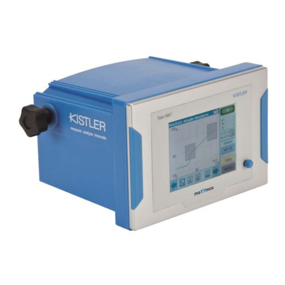
Manuals and User Guides for Kistler maXYmos BL. We have
1
Kistler maXYmos BL manual available for free PDF download: Instruction Manual
Kistler maXYmos BL Instruction Manual (189 pages)
Brand:
Kistler
| Category:
Measuring Instruments
| Size: 7.47 MB
Table of Contents
Table of Contents
3
Important Notes
8
1.1 for Your Safety
8
1.2 Unpacking
8
1.3 Transportation and Storage
8
1.4 Supply
8
Electromagnetic Compatibility (EMC)
9
1.6 Disposal
9
Brief Description
10
Configuration of the Monitor
12
3.1 Interfaces and Signal Paths
12
3.2 Data and Access Paths
13
Parameter Structure - Parameters and Their Storage Locations
14
3.4 Menu Structure - the Three Main Levels
14
3.4.1 PROCESS Menus - Information Pages for Process Status
15
Main Page of the PROCESS Menu Level
15
Scrolling through the Process Information
16
PROCESS Information - Warnings and Alarms
17
PROCESS Information - Checking Piece Counter
18
Switching PROCESS MP Manually
18
SERVICE Menus - Tools for Commissioning and Tests
19
Setup Menus - Structure of the Parameter Configuration Paths
21
SETUP - Configuring Monitor Parameters
22
4.1 Navigating through a Group of Menus
22
4.2 Accessing Setup Level
23
4.3 Global Setup - Global Configuration of Parameters
24
Choosing Language
24
Specifying (Checking and Unchecking) Access Protection
25
Access Rights of the User Groups
27
Setting Date and Time
28
Configuring Measuring Channels
29
Choosing between GLOBAL or MP-Specific Configuration
29
Configuring Channel X GLOBALLY
30
Principle of 2-Point Scaling for Example of Potentiometer
31
Configuring Channel y GLOBALLY (Strain Gage Version)
32
Configuring Channel y GLOBALLY (Piezoelectric Version)
33
Configuring Cycle Control
34
What Is a Cycle
34
Choosing GLOBAL or MP-Specific Cycle Control
35
Configuring Cycle Control GLOBALLY - Access und Menus
36
Cycle Control - Parameters in Detail
37
Specifying Measuring Functions - the Differences
37
Specifying Delta-X
38
Specifying START Condition and STOP Condition
38
Controlling START and STOP with External Signal
38
Examples of START-STOP Combinations
41
START-STOP for y(T) Function of the Piezoelectric Version
42
Specifying Turning Point - Dividing Measurement Curve into POSITIVE and NEGATIVE Parts
44
Cutting Measuring Curve off (Truncating)
45
Specifying Process View
46
Parameter "Capture Only the First NOK EO for Bar Graph
47
Setting up Data Export - from the Maxymos
48
Specifying Hysteresis for Switch Signals and Trigger-Y
49
Configuring Digital Ios
50
Configuring Fieldbus
51
Configuring Warnings and Alarms
52
Display Audio Setup
53
Naming
54
Network Setup
54
4.4 Measuring Program-Specific Setup
55
Accessing MP-Specific Setup
55
Editing Evaluation Objects - EO Editor
56
Function of Tool Buttons in EO Editor
56
Setting up Evaluation Objects [Eos]
57
Specifying Reference Point for the Eos
58
Static EO Reference Point "ABSOLUTE
58
Dynamic Reference Point "TRIGGER-Y
59
Editing TRIGGER-Y Threshold
59
Dynamic Reference Point "BLOCK
60
Editing Reference BLOCK
60
Optimizing BLOCK to Improve Reproducibility
61
Elimination of Dispersion Caused by Block Force
61
Practical Example for Reference BLOCK
62
What Is the Purpose of Dynamic Reference Points
63
Finding Suitable Reference Point
64
No Curve in EO Editor
64
Testing Newly Set up Evaluation Objects
65
Types of Evaluation Object
65
Evaluation Object [EO] UNI-BOX
65
Evaluation Criterion
65
Positioning UNI-BOX over Measurement Curve
66
Obtaining Process Values from the UNI-BOX
66
Specifying Catch Zone of UNI-BOX
67
Which Process Values Does UNI-BOX Provide
68
Evaluation Object [EO] LINE-X
68
Evaluation Criterion
68
Positioning LINE-X over Measurement Curve
69
Obtaining Process Value from LINE-X
69
Specifying Catch Zone for LINE-X
70
Displaying Process Value of LINE-X in Value Table
70
Evaluation Object [EO] LINE-Y
71
Evaluation Criterion
71
Positioning LINE-Y over Measurement Curve
71
Obtaining Process Value of LINE-Y
71
Specifying Catch Zone for LINE-Y
72
Showing Process Value of LINE-Y in Value Table
72
Evaluation Object [EO] NO-PASS
73
Evaluation Criterion
73
Positioning NO-PASS
73
Obtaining Process Value from NO-PASS
73
Evaluation Object [EO] ENVELOPE
74
Evaluation Criterion
74
Positioning ENVELOPE
74
Allocating ENVELOPE to One Part of Curve
75
Activating ENVELOPE Trend Tracking
76
Obtaining Process Value from ENVELOPE
77
Catch Zone for Process Values
77
Significance and Purpose of Catch Zones
77
Specifying Size of a Catch Zone
78
How Are the Catch Zones Formed
78
Configuring Switch Signals
79
Specifying Process View
80
Setting Scaling, Specifying Reference Point for Graphs of Curves
80
Choosing Process Value Source for Value Table
80
Part-Ident-Generator - Specifying SN Source
81
Configuring Channel X - MP-Specific
82
Configuring Channel y - MP-Specific
83
Configuring Cycle Control - MP-Specific
84
4.4.8 the MP Manager
85
Copying a Measuring Program
85
Naming MP
85
Deselecting Unused Measuring Programs
86
Targeted Resetting to Defaults
86
Significance of the Tool Buttons in the Sequence Editor
88
Capturing Curves, Setting up Evaluation (Sequencer Mode Enabled)87
88
Programming Elements
89
Universal Variable Table UVT
90
BIT MASK Element
91
TIMER Element
91
DIALOG Element
91
INPUT Element
93
OUTPUT Element
94
SWITCHING THRESHOLD Element
94
IF/ELSE Element
95
COUNTER Element
96
MEASUREMENT START/STOP Element
97
PIEZO OPERATE Element
98
RESTART Element
99
PROCESS VIEW Including Sequencer Mode
99
Program Example
100
4.5 Configuring Measurement Data Export
105
Configuring Server - Creating and Enabling Target Folder
105
Creating New User in the System (PC)
106
Preparing LAN Connection for Data Export
107
Creating Log Files
108
Connections and Signal Flows
109
5.1 Position of Female Connectors
109
Interfaces
112
Digital-In-Out (X2)
112
Connecting Potentiometer on Channel X (X8)
113
Connecting Sensor with ±10 V- Signal Output on Channel X (X8)
114
Connecting Strain Gage Sensor on Channel X (X6)
115
Connecting Sensor with ±10 V Signal Output an Channel y (X9)
116
Connecting CC-Link (Connector X4)
116
Control Via PLC - the Signal Flowcharts
117
Triggering Piezo-OPERATE by Means of Dig. Input I-OPERATE
117
Coupling Piezo-OPERATE to START
118
Triggering "Test Sensor" Function by Means of PLC
120
Triggering TARE-Y Function by Means of PLC (Taring Channel Y)
120
Triggering ZERO-X Function by Means of PLC (Zeroing Channel
121
Remote Maintenance
122
Remote Access Using VNC
122
PC Software Maxymos PC
123
7.1 Firmware Update
123
Backup-Restore
124
Setup-Editor + Backup-Interpreter
124
Protocol Explorer + Protocol Viewer
125
Fieldbus
126
Feldbus-Configuration
126
General Information
126
Fieldbus -Monitor Setup
127
Basic Settings PROFIBUS
128
Basic Settings Ethernet/Ip
129
Basic Settings PROFINET
130
Basic Settings Ethercat
131
Basic Settings CC-LINK
132
8.1.3 Data Word Interpreter
133
Structure of Telegram
134
Overview
135
Control Signals (Control Bits)
136
Page Control (Control/Config)
140
Page Description
144
Telegram Configuration
147
Input Telegram
147
Output Telegram
148
Data Objects of the Fully Configurable Area
149
Specifying Data Formats
149
Specifying Data Objects
150
8.1.8 Referenztabelle
166
Control / Data Transfer
173
General Information
173
Control: Starting/Stopping Cycle by Means of PLC
173
Data Request: Event OK/NOK Valid
174
Control: Switching Measuring Program by Means of PLC
175
Writing Values from PLC to Maxymos BL with Firmware Version 1.08 (or Earlier)
176
Writing Values from PLC to Maxymos BL Firmware Ver. 1.1
178
Reading Values from Maxymos BL to PLC
179
Triggering Signals TARAY, ZEROX
180
Triggering Signals TESTX, TESTY (Sensor Test)
181
Mounting Monitor
182
9.1 Mounting Options
182
9.2 Case and Mounting Dimensions
183
Front Panel Version Type 5867B0000
183
Desktop/Wall Version Type 5867BXX1X
183
Technical Data
184
Accessories
185
11.1 General Accessories
185
11.2 Sensors
185
Index
186
Advertisement
Advertisement
Related Products
Kistler M2836A Series
Kistler 2516B1
Kistler 2516B12
Kistler 2519A Series
Kistler 4510B Series
Kistler 4703B
Kistler 5015A Series
Kistler 5125C2
Kistler Categories
Measuring Instruments
Accessories
Security Sensors
Amplifier
Analytical Instruments
More Kistler Manuals
Login
Sign In
OR
Sign in with Facebook
Sign in with Google
Upload manual
Upload from disk
Upload from URL