Sign In
Upload
Manuals
Brands
Keithley Manuals
Measuring Instruments
SourceMeter 2612
User Manuals: Keithley SourceMeter 2612 System SMU
Manuals and User Guides for Keithley SourceMeter 2612 System SMU. We have
4
Keithley SourceMeter 2612 System SMU manuals available for free PDF download: Reference Manual, User Manual
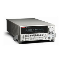
Keithley SourceMeter 2612 Reference Manual (562 pages)
System SourceMeter 2600 series (SMU)
Brand:
Keithley
| Category:
Measuring Instruments
| Size: 14.05 MB
Table of Contents
Table of Contents
7
Safety Precautions
5
List of Figures
17
Table of Contents
18
List of Tables
21
Section 1 Getting Started
25
1 Getting Started
25
Introduction
26
Capabilities and Features
26
Organization of Manual Sections
27
General Information
27
Contact Information
27
Safety Symbols and Terms
27
Unpacking and Inspection
27
Warranty Information
27
Options and Accessories
28
User's and Reference Manuals
29
Front and Rear Panel Familiarization
30
Front Panel Summaries
30
Rear Panel Summaries
33
Cooling Vents
37
Power-Up
38
Line Power Connection
38
Power-Up Sequence
39
Beeper
39
Display Modes
40
Editing Controls
41
Source and Compliance Editing
41
Menu Navigation
42
Menu Types
43
Table 1-3 Main Menu
43
Interface Selection
44
Table 1-4 Configuration Menus
44
To Select the GPIB Interface
45
To Select the RS-232 Interface
45
Error and Status Messages
45
Default Settings
45
Front Panel Setups
45
Remote Operation Setups
46
Table 1-5 Default Settings
47
Remote Programming
48
Requesting Readings
48
Requesting Command Settings
48
Section 2 Tsp Programming
49
Introduction
51
Test Script Processor (TSP)
51
Run-Time Environment
51
Queries
52
Scripts
52
Named Scripts
52
Functions
53
Scripts that Create Functions
53
2 TSP Programming
51
Programming Overview
54
What Is a Chunk
54
What Is a Script
54
Run-Time Environment
55
Non-Volatile Memory
55
TSP Programming Levels
56
Programming Model for Scripts
56
Installing the Test Script Builder Software
57
System Connections
57
Gpib
57
Rs-232
58
Using Test Script Builder
59
Programming Interaction
60
Project Navigator
60
Script Editor
60
Starting Test Script Builder
60
Instrument Console
61
Opening Communications
61
Creating and Modifying a Script
63
Script Launch Configuration
67
Launching a Script
70
Running a TSP File
71
Instrument Console
72
File Management Tasks
78
Using the Expanded System
81
Display User-Defined Messages
82
Creating a User Script
84
Saving a User Script
85
Running a User Script
86
Modifying a User Script
88
Factory Scripts
90
Differences: Remote Versus Local State
91
Memory Considerations for the Runtime Environment
92
Test Script Language (TSL) Reference
93
Operators
94
Tables/Arrays
95
Precedence
96
Concatenation
97
Branching
98
Loop Control
99
Standard Libraries
101
Section 3 Dut Test Connections
105
DUT Test Connections
105
Input/Output Connectors
106
Input/Output lo and Chassis Ground
107
Sensing Methods
109
2 Wire Local Sensing
110
4 Wire Remote Sensing
111
Sense Mode Selection
112
Table 3-1 Selecting the Sense Mode from the Front Panel
112
Table 3-2 Commands to Select Sense Mode
112
Contact Check Connections
113
Multiple SMU Connections
114
Guarding and Shielding
116
Guarding
116
Noise Shield
117
Figure 3-16
120
Safety Shield
120
Figure 3-18
121
Using Shielding and Guarding Together
122
Test Fixture
123
Floating a SMU
124
Figure 3-23 Floating the Series 2600
125
Output-Off States
127
Section 4 Basic Operation
129
Basic Operation
129
Figure 4-4 Contact Check Measurements
129
Table 4-1 Source-Measure Capabilities
129
Overview
130
Operation Overview
130
Compliance Limit
131
Setting the Compliance Limit
132
Basic Circuit Configurations
133
Table 4-4 Auto Zero Settings
134
Operation Considerations
134
Warm-Up
134
Auto Zero
134
NPLC Caching
134
Basic Source-Measure Procedure
136
Front Panel Source-Measure Procedure
136
Remote Source-Measure Procedure
137
Table 4-6 Basic Source-Measure Commands
138
Measure Only
139
Sink Operation
140
Ohms Measurements
140
Ohms Calculations
140
Ohms Ranging
140
Basic Ohms Measurement Procedure
140
Ohms Sensing
141
Sense Selection
142
Remote Ohms Programming
143
Power Measurements
144
Power Calculations
144
Basic Power Measurement Procedure
144
Remote Power Programming
144
Overview
145
Contact Check Measurements
145
Contact Check Commands
146
Contact Check Programming Example
147
Section 5 Sweep Operation
149
Sweep Operation
149
Table 5-2 Staircase Sweep Functions
149
Table 5-3 Pulse Sweep Functions
149
Overview
150
Section Overview
150
Sweep Overview
150
Sweep Characteristics
151
Linear Staircase Sweeps
151
Logarithmic Staircase Sweeps
152
Figure 5-3 Logarithmic Staircase Sweep (1V to 10V, Five Steps)
153
Table 5-1 Logarithmic Sweep Points
153
Figure 5-4 Pulse Sweep Example
154
Pulse Sweeps
154
Sweep Measurement Storage
155
Sweep Functions
155
Staircase Sweep Functions
156
Figure 5-2 Linear Staircase Sweep
157
Table 5-4 Custom Sweep Functions
157
Table 5-5 Sweep Example Parameters
157
Custom Sweep Functions
157
Running Sweeps
157
Front Panel
157
Section 6 Range, Digits, Speed, Rel, and Filters
161
Range, Digits, Speed, Rel, and Filters
161
Range
162
Available Ranges
162
Maximum Source Values and Readings
163
Ranging Limitations
163
Manual Ranging
163
Auto Ranging
163
Low Range Limits
163
Range Considerations
164
Range Programming
164
Table 6-2 Range Commands
165
Table 6-3 Digits Commands
166
Overview
162
Digits
166
Setting Display Resolution
166
Remote Digits Programming
166
Speed
166
Table 6-4 Speed Command
167
Remote Speed Programming
167
Setting Speed
167
Rel
168
Front Panel Rel
168
Table 6-5 Rel Commands
169
Remote Rel Programming
169
Filters
170
Filter Types
170
Response Time Considerations
170
Front Panel Filter Control
170
Response Time
171
Table 6-6 Filter Commands
173
Remote Filter Programming
173
Section 7 Buffer (Data Store)
175
Buffer (Data Store)
175
Overview
176
Front Panel Data Store
176
Buffer Configuration
176
Storing Readings
177
Recalling Readings
177
Table 7-1 Data Store Commands
178
Data Store Overview
176
Remote Data Store
178
Data Store Commands
178
Reading Buffers
179
Table 7-2 Buffer Storage Control Attributes
180
Table 7-3 Buffer Read-Only Attributes
180
Table 7-4 Buffer Control Programming Examples
180
Table 7-5 Buffer Read-Only Attribute Programming Examples
180
Table 7-6 Recall Attributes
181
Time and Date Values
181
Table 7-7 Buffer Status Bits
182
Buffer Status
182
Dynamically Allocated Buffers
182
Buffer Programming Examples
183
Section 8 Source-Measure Concepts
187
Source-Measure Concepts
187
Compliance Limit
188
Maximum Compliance
188
Overview
188
Compliance Principles
189
Sweep Waveforms
189
Staircase Sweeps
189
Figure 8-2 Pulse Sweep Example
190
Overheating Protection
190
Power Equations to Avoid Overheating
190
Table 8-2 Model 2601/2602 Maximum Duty Cycle Equation Constants
192
Table 8-3 Model 2611/2612/2635/2636 Maximum Duty Cycle Equation Constants
192
Pulse Sweeps
190
Operating Boundaries
193
Source or Sink
193
Continuous Power Operating Boundaries
194
I-Source Operating Boundaries
195
V-Source Operating Boundaries
199
Figure 8-11 Source I Configuration
202
Source I Measure I, Source V Measure V
202
Basic Circuit Configurations
202
Figure 8-12 Source V Configuration
203
Measure Only (V or I)
203
Source V
203
Contact Check
204
Guard Overview
205
Guard Connections
206
Figure 8-16 Pulse Period
208
Figure 8-17 Pulse Rise and Fall Times
208
Pulse Concepts
208
Pulse Period
208
Pulse Rise and Fall Times
208
Pulse Duty Cycle
209
Table 8-5 Current Source Gain-Bandwidth
210
Reduction in Gain-Bandwidth
210
Section 9 System Expansion (Tsp-Link)
211
In this Section:
211
Master and Slaves
212
System Configurations
212
Overview
212
Figure 9-1 TSP-Link Connections
213
Assigning Node Numbers
213
Initialization
213
Resetting the TSP-Link
214
Using the Expanded System
215
Accessing Nodes
215
System Behavior
215
Triggering with TSP-Link
216
TSP Advanced Features
216
Table 9-2 TSP-Link Network Group Functions
219
Using Groups to Manage Nodes on the TSP-Link Network
219
Running Parallel Test Scripts
220
Using the Data Queue for Real-Time Communication
221
Copying Test Scripts Across the TSP-Link Network
222
Removing Stale Values from the Reading Buffer
222
Section 10 Digital I\/O and Triggering
225
Digital I/O and Triggering
225
Figure 10-1 Digital I/O Port
226
Overview
226
Digital I/O Configuration
227
Controlling Digital I/O Lines
228
Output Enable (Models 2601/2602)
231
Front Panel Control of Output Enable
232
TSP-Link Synchronization Lines
234
Connecting to TSP-Link
234
Remote TSP-Link Synchronization Line Commands
234
Triggering
236
Triggering Types
236
Measurement Triggering
236
Front Panel Triggering
237
Remote Triggering
238
Hardware Trigger Modes
239
Understanding Synchronous Triggering Modes
244
Section 11 Communications Interfaces
249
Communications Interfaces
249
GPIB Operation
250
GPIB Standards
250
GPIB Connections
250
Overview
250
Figure 11-1 IEEE-488 Connector
251
Primary Address
252
Terminator
253
Selecting an Interface
250
General Bus Commands
254
REN (Remote Enable)
254
IFC (Interface Clear)
254
LLO (Local Lockout)
254
GTL (Go to Local)
254
DCL (Device Clear)
254
SDC (Selective Device Clear)
255
GET (Group Execute Trigger)
255
SPE, SPD (Serial Polling)
255
Front Panel GPIB Operation
255
Error and Status Messages
255
GPIB Status Indicators
255
LOCAL Key
256
RS-232 Interface Operation
256
Setting RS-232 Interface Parameters
256
Sending and Receiving Data
257
Baud Rate
257
Data Bits and Parity
258
Flow Control (Signal Handshaking)
258
RS-232 Connections
259
Section 12 Instrument Control Library
261
Instrument Control Library
261
Command Programming Notes
262
Functions and Attributes
263
TSP-Link Nodes
264
Logical Instruments
265
Reading Buffers
265
Time and Date Values
267
ICL Functions and Attributes
268
Data Queue Functions
275
Delay Function
277
Display Functions and Attributes
283
Errorqueue Functions and Attribute
295
Exit Function
296
Gpib Attribute
299
Makegetter Functions
302
Printbuffer and Printnumber Functions
303
Reset Function
305
Setup Functions and Attribute
308
Status Function and Attributes
336
Timer Functions
368
Trigger Functions
369
Tsplink Function and Attributes
370
Userstring Functions
376
Waitcomplete Function
378
Factory Scripts
379
Introduction
380
Kipulse
390
Advanced Features for Models 2635 and 2636
391
Additional Hardware Triggering Parameters
392
Flash Firmware Upgrade
413
Section 14 Display Operations
415
Display Operations
415
Display Functions and Attributes
416
Display Features
416
Display Screen
416
Measurement Functions
416
Display Resolution
416
Measurement Functions
417
Display Messages
418
Displaying Text Messages
419
Input Prompting
421
Parameter Value Prompting
422
Annunciators
423
LOCAL Lockout
424
Load Test Menu
424
Saving a User Script
425
Adding USER TESTS Menu Entries
425
Deleting USER TESTS Menu Entries
426
Running a Test from the Front Panel
426
Display Triggering
426
Key-Press Codes
427
Section 15 Performance Verification
431
Performance Verification
431
Verification Test Requirements
432
Environmental Conditions
432
Warm-Up Period
432
Introduction
432
Line Power
433
Recommended Test Equipment
433
Verification Limits
433
A Specifications
433
Restoring Factory Defaults
434
Performing the Verification Test Procedures
435
Test Summary
435
Test Considerations
435
Setting the Source Range and Output Value
435
Setting the Measurement Range
436
Output Voltage Accuracy
436
Voltage Measurement Accuracy
438
Output Current Accuracy
439
Model 2635/2636 Output Current Accuracy 1Na to 100Na Ranges
441
Current Measurement Accuracy
444
Series 2600 Current Measurement Accuracy 100Na and Higher
444
Model 2635/2636 Current Measurement Accuracy 100Pa to 100Na Ranges
445
Introduction
447
Error Summary
448
Calibration Cycle
449
Calibration Errors
451
Calibration Commands
453
Calibration Procedure
454
Routine Maintenance
469
Introduction
470
Front Panel Tests
471
Reading Errors
499
Common Commands
505
Script Command Equivalents
506
Command Reference
507
D Status Model
509
Overview
510
Status Function Summary
516
Programming and Reading Registers
517
Reading Registers
518
Service Request Enable Register
520
Enable and Transition Registers
521
Status Register Sets
523
Standard Event Register
524
Operation Event Registers
526
Measurement Event Registers
532
Register Programming Example
535
Error Queue
536
Introduction
539
Test System Used
540
Single Measurement Rates
541
Digital I/O Handshaking
542
Measure to GPIB
543
Measure to GPIB
544
S-901-01 Rev. C / January
545
Rate
555
Advertisement
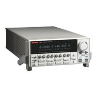
Keithley SourceMeter 2612 Reference Manual (594 pages)
Brand:
Keithley
| Category:
Measuring Instruments
| Size: 7.29 MB
Table of Contents
Table of Contents
7
List of Illustrations
19
Capabilities and Features
28
Getting Started
28
Introduction
28
Contact Information
29
General Information
29
Organization of Manual Sections
29
Safety Symbols and Terms
29
Warranty Information
29
Unpacking and Inspection
30
Options and Accessories
31
Front and Rear Panel Familiarization
32
Front Panel Summaries
32
Getting Started
32
Rear Panel Summaries
32
Reference Manual
32
User's Manual
32
Getting Started
33
Cooling Vents
38
Line Power Connection
39
Power-Up
39
Power-Up Sequence
40
Beeper
41
Display Modes
41
Figure 1-3 Display Modes
42
Editing Controls
43
Source and Compliance Editing
43
Menu Navigation
44
Configuration Menus
45
Main Menu
45
Menus
45
Table 1-1 Main Menu
46
Table 1-2 Configuration Menus
47
Error and Status Messages
48
GPIB Interface
48
Interface Selection
48
RS-232 Interface
48
Default Settings
49
Front Panel Setups
49
Remote Operation Setups
50
Table 1-3 Default Settings
51
Remote Programming
52
Requesting Command Settings
52
Requesting Readings
52
TSP Programming Fundamentals
54
Figure 2-1 Script Example
60
Figure 2-3 GPIB Cable
63
Figure 2-10 Creating a New Script File
73
Figure 2-18 Instrument Console Icons
81
Figure 2-23 Deleting a Project
90
Table 2-2 Example Script Using a Function
93
Figure 3-1 Input/Output Terminal Blocks
117
Figure 3-5 4-Wire Connections (Remote Sense)
122
Figure 3-6 Contact Check Connections
123
Table 3-2 Commands to Select Sense Mode
123
Figure 3-7 Two Smus Connected to a 3-Terminal Device (Local Sense)
125
Figure 3-8 Three Smus Connected to a 3-Terminal Device (Local Sense)
125
Table 4-1 Source-Measure Capabilities
137
Basic Operation
138
Table 4-3 Compliance Commands
141
Table 4-4 Auto Zero Settings
144
Table 4-5 Auto Zero Command and Options
145
Table 4-7 Basic Source-Measure Commands
151
Table 4-8 Basic Contact Check Commands
161
Table 5-2 Staircase Sweep Functions
163
Table 5-3 Pulse Sweep Functions
163
Table 5-4 Custom Sweep Functions
163
Table 5-5 Sweep Example Parameters
173
Table 6-2 Range Commands
182
Table 6-3 Digits Commands
184
Table 6-4 Speed Command
185
Table 6-5 Rel Commands
187
Table 6-6 Filter Commands
191
Table 7-1 Data Store Commands
197
Table 7-6 Recall Attributes
201
Table 7-7 Buffer Status Bits
202
Figure 8-12 Source V Configuration
232
Figure 8-16 Pulse Period
238
Figure 8-17 Pulse Rise and Fall Times
239
Figure 9-1 TSP-Link Connections
243
Figure 10-1 Digital I/O Port
251
Table 10-2 Digital I/O Commands
255
Figure 11-1 IEEE-488 Connector
263
Figure 11-2 IEEE-488 Connections
264
Table 11-1 General Bus Commands
267
Table 11-4 PC Serial Port Pinout
274
Table14-2 Bit Identification for Annunciators
458
Table14-3 Keycodes to Send for Display.sendkey
462
Table14-4 Keycode Values Returned for Display.getlastkey
463
Figure 8-14 Contact Check Circuit Configuration
585
Table 15-1 Recommended Verification Equipment
588
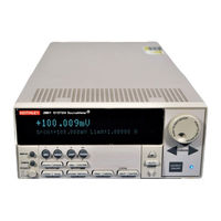
Keithley SourceMeter 2612 User Manual (114 pages)
Series 2600 System SourceMeter Instruments
Brand:
Keithley
| Category:
Measuring Instruments
| Size: 4.02 MB
Table of Contents
Table of Contents
9
Safety Precautions
7
List of Tables
13
Section 1 Front and Rear Panel Operation
15
Topic Page
15
Front and Rear Panel Operation
16
Front and Rear Panel Familiarization
16
Front Panel Summaries
16
Rear Panel Summaries
16
Safety Symbols and Terms
16
Figure 1-1 Models 2601, 2611, 2602, 2612, 2635, and 2636 Front Panels
17
Figure 1-2 Model 2601/2602/2611/2612 Rear Panels
20
Figure 1-3 Model 2635 and 2636 Rear Panels
22
What Are the Source-Measure Capabilities
24
Model 2601 and Model 2602
24
Model 2611 and Model 2612
24
Model 2635 and Model 2636
24
How Do I Power-Up the Instrument
25
How Do I Make Measurements
26
Connect the DUT
26
Select Source and Set Source Level
26
Set Compliance Limit
26
Select Measurement Function and Range
27
Turn Output on
27
Make Measurements
27
Turn Output off
27
Figure 1-5 Interlock Circuit
29
How Do I Use the Buffer
30
Connect the DUT
30
Set up Source and Measure Functions
30
Configure the Buffer
30
Turn on the Output
31
Store Readings
31
Turn off the Output
31
Recall Readings
31
Figure 1-7 Buffer Display Format
31
Section 2 Remote Operation
33
How Do I Use the Remote Interface
34
Connect to the Interface
34
Select the Interface
34
Remote Operation
34
How Do I Use Test Script Builder
35
Configure the Interface
35
Run Test Script Builder
35
Figure 2-3 Test Script Builder Initial Startup Screen
37
Open and Close an Instrument Resource
38
Figure 2-4 Instrument Console Control Icons
38
How Do I Use TSB to Make Measurements
39
Save and Clear Console Window
39
Select Command and Language Reference Views
39
Reset Instrument
40
Select Source Function and Set Output Value
40
Set Compliance Value and Measure Range
40
Turn on Output
40
Make a Measurement
40
Print the Result
40
Turn off Output
41
How Do I Use Other Programs
42
Using Labview
42
Figure 2-7 Labview Source-Measure Example Block Diagram
43
Using Visual Basic
44
Figure 2-9 Example Program Test Results
46
Section 3 Test Script Processor Interaction
47
Test Script Processor Interaction
47
What Is a Script
48
Factory Scripts
48
User Scripts
48
How Do I Run a Script from the Front Panel
48
How Do I Interact with Scripts Using Test Script Builder
49
Running a Factory Script
49
Modifying a Factory Script
51
Figure 3-2 Importing a Factory Script Project from the Series 2600
52
Figure 3-3 Kigeneral Project Imported into the Test Script Builder
53
Figure 3-4 Run Configuration Example - Main Tab Shown
55
Running the User Script
56
Deleting a User Script and User Tests
57
How Do I Use Other Programs
57
Using Labview
57
Figure 3-6 Labview Source Step Example
58
Using Visual Basic
59
Figure 3-7 GUI after Loading the Non-Function Script (GPIB)
61
Figure 3-8 GUI after Running the Non-Function Script (GPIB)
62
Figure 3-9 GUI after Loading and Running the Function Script (GPIB)
64
Figure 3-10 GUI after Calling the Function (GPIB)
65
Section 4 Controlling Multiple Series 2600S (Tsp-Link)
67
Controlling Multiple Series 2600S (TSP-Link)
67
How Do I Set up the TSP-Link System
68
Connect the TSP-Link System
68
Assign Node Numbers
68
How Do I Use the Expanded System
69
Accessing Resources of TSP-Link Nodes
69
Reset the TSP-Link
69
Check the State of the TSP-Link System
69
Using Node[N]
69
Running Scripts in a TSP-Link System
70
Using the Alias (Localnode)
70
A Specifications
71
Specifications
72
Appendix B Frequently Asked Questions
97
Frequently Asked Questions
97
How Do I Optimize Performance
98
Setting Speed
98
Disabling Auto Zero to Increase Speed
98
How Do I Use the Digital I/O Port
98
Digital I/O Port Terminals
98
Controlling the Digital I/O Port
99
How Do I Trigger Other Instruments
99
Triggering a Scanner
99
Programming Triggering
100
How Do I Generate a Service Request
100
Setting up a Service Request
100
Service Request Programming Example
100
Polling for Srqs
100
How Do I Store Measurements in Non-Volatile Memory
101
Front Panel Operation
101
Remote Programming
101
How Do I Stack Channels to Output Higher Voltage
102
How Do I Parallel Channels to Output Higher Current
104
How Do I Make Contact Check Measurements
104
Contact Check Connections
104
Contact Check Programming Example
105
How Do I Make Low-Current Measurements
106
Low-Current Connections
106
Low-Current Measurement Programming Example
107
Advertisement
Keithley SourceMeter 2612 User Manual (108 pages)
Brand:
Keithley
| Category:
Measuring Instruments
| Size: 3.66 MB
Table of Contents
Table of Contents
7
1 Front Panel Operation
13
Safety Symbols and Terms
14
Front and Rear Panel Familiarization
14
Figure 1-1 Series 2600 Front Panels
15
Figure 1-2 Series 2600 Rear Panels
18
What Are the Source-Measure Capabilities
20
Models 2601 and 2602
20
Models 2611 and 2612
20
How Do I Power-Up the Instrument
21
How Do I Make Measurements
22
Figure 1-4 Interlock Circuit
25
Figure 1-5 Display Modes
26
How Do I Use the Buffer
27
Figure 1-6 Buffer Display Format
29
2 Remote Operation
31
How Do I Use the Remote Interface
32
Figure 2-1 GPIB Cable
32
Figure 2-2 RS-232 Cable
32
Gpib Interface Configuration
33
How Do I Use Test Script Builder
34
Figure 2-3 Test Script Builder Initial Startup Screen
36
Figure 2-4 Instrument Console Control Icons
37
Figure 2-5 Select Instrument Resource Dialog Box
38
How Do I Use TSB to Make Measurements
39
How Do I Use Other Programs
42
Using Labview
42
Figure 2-7 Labview Source-Measure Example Block Diagram
43
Using Visual Basic
44
Figure 2-9 Example Program Test Results
46
3 Test Script Processor Interaction
49
What Is a Script
50
Factory Scripts
50
User Scripts
50
How Do I Run a Script from the Front Panel
50
How Do I Interact with Scripts Using Test Script Builder
51
Running a Factory Script
52
Modifying a Factory Script
54
Figure 3-2 Importing a Factory Script Project from the Series 2600
55
Figure 3-3 Kigeneral Project Imported into the Test Script Builder
56
Figure 3-4 Run Configuration Example - Main Tab
58
Figure 3-5 Run Configuration Example - Script Attributes Tab
59
Running the User Script
60
Deleting a User Script and User Tests
61
How Do I Use Other Programs
62
Using Labview
62
Figure 3-6 Labview Source Step Example
63
Using Visual Basic
64
Figure 3-7 GUI after Loading the Non-Function Script (GPIB)
65
Figure 3-8 GUI after Running the Non-Function Script (GPIB)
68
Figure 3-9 GUI after Loading and Running the Function Script (GPIB)
70
Figure 3-10 GUI after Calling the Function (GPIB)
72
4 Controlling Multiple Sourcemeters (TSP-Link)
73
How Do I Set up the TSP-Link System
74
How Do I Use the Expanded System
76
Accessing Resources of TSP-Link Nodes
76
Running Scripts in a TSP-Link System
77
Appendix Title
79
Specifications
79
Frequently Asked Questions
87
How Do I Optimize Performance
88
Setting Speed
88
Disabling Auto Zero to Increase Speed
88
How Do I Use the Digital I/O Port
89
Digital I/O Port Terminals
89
Controlling the Digital I/O Port
89
How Do I Trigger Other Instruments
91
Triggering a Scanner
91
Programming Triggering
91
How Do I Generate a Service Request
92
Setting up a Service Request
92
Service Request Programming Example
92
Polling for Srqs
92
How Do I Store Measurements in Non-Volatile Memory
93
Front Panel Operation
93
Remote Programming
93
How Do I Stack Channels to Output Higher Voltage
95
Appendix Figure Title
96
Figure B-3 Stacking Channels for Higher Voltage
96
How Do I Parallel Channels to Output Higher Current
97
How Do I Make Contact Check Measurements
98
Contact Check Connections
98
Contact Check Programming Example
99
Advertisement
Related Products
Keithley SourceMeter 2611
Keithley 2614B
Keithley 2611B
Keithley 2612B
Keithley 2612A
Keithley 2611A
Keithley SourceMeter 2602
Keithley SourceMeter 2601
Keithley SourceMeter 2636B
Keithley 2635
Keithley Categories
Measuring Instruments
Multimeter
Test Equipment
Power Supply
Switch
More Keithley Manuals
Login
Sign In
OR
Sign in with Facebook
Sign in with Google
Upload manual
Upload from disk
Upload from URL