Keithley 2601 User Manual
Series 2600
system sourcemeter instruments
Hide thumbs
Also See for 2601:
- User manual (108 pages) ,
- Reference manual (562 pages) ,
- Reference manual (594 pages)

Related Manuals for Keithley 2601


Summary of Contents for Keithley 2601
- Page 1 Series 2600 System SourceMeter ® User’s Manual 2600S-900-01 Rev. C / January 2008 G R E A T E R M E A S U R E C O N F I D E N C E...
- Page 3 WARRANTY Keithley Instruments, Inc. warrants this product to be free from defects in material and workmanship for a period of one (1) year from date of shipment. Keithley Instruments, Inc. warrants the following items for 90 days from the date of shipment: probes, cables, software, rechargeable batteries, diskettes, and documentation.
- Page 5 Keithley Instruments, Inc. is strictly prohibited. TSP, TSP-Link, and TSP-Net are trademarks of Keithley Instruments, Inc. All Keithley Instruments product names are trademarks or registered trademarks of Keithley Instruments, Inc. Other brand names are trademarks or registered trademarks of their respective holders Cleveland, Ohio, U.S.A.
-
Page 7: Safety Precautions
Keithley Instruments products are designed for use with electrical signals that are rated Measurement Category I and Measurement Category II, as described in the International Electrotechnical Commission (IEC) Standard IEC 60664. Most measurement, control, and data I/O signals are Measurement Category I and must not be directly connected to mains voltage or to voltage sources with high transient over-voltages. - Page 8 To maintain protection from electric shock and fire, replacement components in mains circuits - including the power transformer, test leads, and input jacks - must be purchased from Keithley Instruments. Standard fuses with applicable national safety approvals may be used if the rating and type are the same.
-
Page 9: Table Of Contents
Rear panel summaries ................. 1-2 Safety symbols and terms ..............1-2 What are the source-measure capabilities? ..........1-10 Model 2601 and Model 2602.............. 1-10 Model 2611 and Model 2612 .............. 1-10 Model 2635 and Model 2636.............. 1-10 How do I power-up the instrument?............ - Page 10 ® Table of Contents Series 2600 System SourceMeter Instruments User’s Manual Controlling the Digital I/O port.............. B-3 How do I trigger other instruments? ............B-3 Triggering a scanner................B-3 Programming triggering ............... B-4 How do I generate a service request? ............
- Page 11 List of Figures Section Figure Title Page Figure 1-1 Models 2601, 2611, 2602, 2612, 2635, and 2636 front panels..1-3 Figure 1-2 Model 2601/2602/2611/2612 rear panels ........1-6 Figure 1-3 Model 2635 and 2636 rear panels ..........1-8 Figure 1-4 Model 2602/2612 Low-Noise Chassis Ground Banana Jack and Chassis Screw................1-14...
- Page 12 ® List of Figures Series 2600 System SourceMeter Instruments User’s Manual This page left blank intentionally. Document Number: 2600S-900-01 Rev. C / January 2008...
-
Page 13: List Of Tables
Connectors and triax cable conductors ......... 1-9 Table 1-2 Triax connector on ground module ..........1-9 Table 1-3 Model 2601 and 2602 source-measure capabilities ....1-10 Table 1-4 Model 2611 and 2612 source-measure capabilities..... 1-10 Table 1-5 Model 2635 and 2636 source-measure capabilities .... - Page 14 ® List of Tables Series 2600 System SourceMeter Instruments User’s Manual This page left blank intentionally. Document Number: 2600S-900-01 Rev. C / January 2008...
-
Page 15: Topic Page
Front panel summaries..............Rear panel summaries ..............Safety symbols and terms ............. What are the source-measure capabilities?........1-10 Model 2601 and Model 2602 ............1-10 Model 2611 and Model 2612 ............1-10 Model 2635 and Model 2636 ............1-10 How do I power-up the instrument?.......... -
Page 16: Front And Rear Panel Operation
1-1. The descriptions of the front panel controls follow Figure 1-1. Rear panel summaries The rear panels of the Models 2601/2602 and 2611/2612 are shown in Figure 1-2 on page 1-6. The rear panels of the Models 2635 and 2636 are shown in Figure 1-3 on page 1-8. -
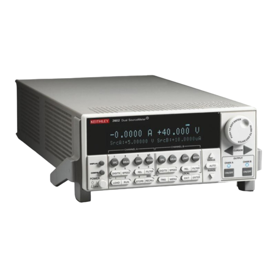
Page 17: Figure 1-1 Models 2601, 2611, 2602, 2612, 2635, And 2636 Front Panels
Figure 1-1 Models 2601, 2611, 2602, 2612, 2635, and 2636 front panels NOTE The Models 2601, 2611, and 2635 have one SourceMeter channel (Channel A) and the Models 2602, 2612, and 2636 have two SourceMeter channels (Channel A and Channel B). - Page 18 Instruments User’s Manual 2. Source-measure setup, performance control and special operation: Top Row – Source-measure setup Model 2601/2611/2635 and Model 2602/2612/2636: Channel A – Selects the source function (V or A) and places cursor in the source field for editing.
- Page 19 ® Series 2600 System SourceMeter Instruments User’s Manual Section 1: Front and Rear Panel Operation 3. Range keys: Selects the next higher or lower source or measure range. AUTO Enables or disables source or measure auto range. 4. Output control and LED status indicator: OUTPUT ON/OFF Turns source output on or off.
-
Page 20: Figure 1-2 Model 2601/2602/2611/2612 Rear Panels
® Section 1: Front and Rear Panel Operation Series 2600 System SourceMeter Instruments User’s Manual Figure 1-2 Model 2601/2602/2611/2612 rear panels Return to Section Topics 2600S-900-01 Rev. C / January 2008... - Page 21 PC (Keithley Instruments Model 7009-5). 8. TSP-Link Expansion interface that allows a Series 2600 and other TSP-enabled instruments to trigger and communicate with each other. Use a category 5e or higher LAN crossover cable (Keithley Instruments part number CA-180-3A). 9. Power module Contains the AC line receptacle and power line fuse.
-
Page 22: Figure 1-3 Model 2635 And 2636 Rear Panels
® Section 1: Front and Rear Panel Operation Series 2600 System SourceMeter Instruments User’s Manual Figure 1-3 Model 2635 and 2636 rear panel Model 2635 WARNING: WARNING: NO INTERNAL OPERATOR SERVICABLE PARTS,SERVICE BY QUALIFIED PERSONNEL ONLY. NO INTERNAL OPERATOR SERVICABLE PARTS,SERVICE BY QUALIFIED PERSONNEL ONLY. SENSE CHANNEL A SENSE... - Page 23 PC (Keithley Instruments Model 7009-5). 7. TSP-Link Expansion interface that allows a Series 2600 and other TSP-enabled instruments to trigger and communicate with each other. Use a category 5e or higher LAN crossover cable (Keithley Instruments part number CA-180-3A). 8. Power module Contains the AC line receptacle and power line fuse.
-
Page 24: What Are The Source-Measure Capabilities
See the specifications in Appendix A of this manual as well as Sections 4 and 8 of the Series 2600 Reference Manual for more detailed information. Model 2601 and Model 2602 Basic DC source-measure capabilities for the Models 2601 and 2602 are listed in Table 1-3. -
Page 25: How Do I Power-Up The Instrument
MENU > LINE-FREQ > 50Hz, 60Hz, or AUTO. (When set to AUTO, the SourceMeter will automatically detect the power line frequency at power-up.) 1. Instrument will display actual model number: 2601, 2602, 2611, 2612, 2635, or 2636. 2. Instrument will display actual model number: 2601, 2602, 2611, 2612, 2635, or 2636. -
Page 26: How Do I Make Measurements
Press the up RANGE key, and select the 20V source range (Model 2611/2612/2635/2636) or 40V source range (Model 2601/2602). Use the lowest possible source range for best accuracy. Use the CURSOR keys to move the cursor to the 10s digit, then press the navigation wheel to enter the EDIT mode (EDIT indicator displays). -
Page 27: Select Measurement Function And Range
® Series 2600 System SourceMeter Instruments User’s Manual Section 1: Front and Rear Panel Operation Step 4: Select measurement function and range Put the Model 2602/2612/2636 in the single-channel display mode with the DISPLAY key, then select the current measurement function by pressing MEAS or MODE. Select the measurement range with the RANGE keys. - Page 28 ® Section 1: Front and Rear Panel Operation Series 2600 System SourceMeter Instruments User’s Manual Figure 1-4 Model 2602/2612 Low-Noise Chassis Ground Banana Jack and Chassis Screw Model 2636 1-14 Return to Section Topics 2600S-900-01 Rev. C / January 2008...
-
Page 29: Figure 1-5 Interlock Circuit
® Series 2600 System SourceMeter Instruments User’s Manual Section 1: Front and Rear Panel Operation Figure 1-5 Interlock circuit Figure 1-6 Display modes 2600S-900-01 Rev. C / January 2008 Return to Section Topics 1-15... -
Page 30: How Do I Use The Buffer
Using the procedure described in “How do I make measurements?” on page 1-12, set up source and measure functions: • Source function: volts • Source range: 20V (2611/2612/2635/2636) or 40V (2601/2602) • Source value: 10V • Measure function: current • Measure range: auto Step 3: Configure the buffer From the front panel, press the STORE key. -
Page 31: Turn On The Output
® Series 2600 System SourceMeter Instruments User’s Manual Section 1: Front and Rear Panel Operation Step 4: Turn on the output Press the CHAN A (Model 2602/2612/2636) OUTPUT ON/OFF key to turn on the source output. Step 5: Store readings Press the STORE key to enable storage. - Page 32 ® Section 1: Front and Rear Panel Operation Series 2600 System SourceMeter Instruments User’s Manual This page left blank intentionally. 1-18 Return to Section Topics 2600S-900-01 Rev. C / January 2008...
- Page 33 Section 2 Remote Operation In this section: Topic Page How do I use the remote interface?..........Connect to the interface ............... Select the interface ............... Configure the interface ..............How do I use Test Script Builder? ........... Run Test Script Builder ..............
-
Page 34: Remote Operation
GPIB (IEEE-488) and RS-232 connectors, and make connections as follows: • GPIB – Use a shielded IEEE-488 cable such as the Keithley Instruments Model 7007 to connect the Series 2600 IEEE-488 connector to the GPIB connector on the computer (see Figure 2-1). -
Page 35: How Do I Use Test Script Builder
See Section 2 of the Series 2600 Reference Manual for complete details on using the Test Script Builder. Step 1: Run Test Script Builder Run the Test Script Builder program in the Keithley Instruments folder in the usual manner. The initial startup screen shown in Figure 2-3 on page 2-5 will be displayed. - Page 36 ® Section 2: Remote Operation Series 2600 System SourceMeter Instruments User’s Manual Run – Runs scripts. Window – Selects which window to display. Help – Provides access to online help files. Project Navigator pane The window pane on the left side is where the Project Navigator resides. The navigator consists of created project folders and the script files (.tsp) created for each project.
-
Page 37: Figure 2-3 Test Script Builder Initial Startup Screen
® Series 2600 System SourceMeter Instruments User’s Manual Section 2: Remote Operation Figure 2-3 Test Script Builder initial startup screen 2600S-900-01 Rev. C / January 2008 Return to Section Topics... -
Page 38: Open And Close An Instrument Resource
® Section 2: Remote Operation Series 2600 System SourceMeter Instruments User’s Manual Figure 2-4 Instrument console control icons Step 2: Open and close an instrument resource Before you can send commands or run scripts to control the Series 2600, you must first open the instrument resource as follows: Click on the Open Instrument icon (see Figure... -
Page 39: How Do I Use Tsb To Make Measurements
® Series 2600 System SourceMeter Instruments User’s Manual Section 2: Remote Operation Figure 2-5 Select Instrument Resource dialog box Step 3: Save and clear console window You can save and clear the console window as follows: • Save console – Click on the Menu arrow (Figure 2-3), choose Save Console, then choose the folder and filename desired. -
Page 40: Reset Instrument
Step 2: Select source function and set output value Enter the following commands to select the source voltage function, set the source range to 20V (Model 2611/2612/2635/2636) or 40V Model 2601/2602), and set the source value to 10V: smua.source.func = smua.OUTPUT_DCVOLTS (Use for Model 2601/2602) smua.source.rangev = 40... -
Page 41: Turn Off Output
Step 7: Turn off output Send the following command to turn off the output when measurements are complete: smua.source.output =smua.OUTPUT_OFF Figure 2-6 Source-measure command sequence in console window (2601/2602 version shown) 2600S-900-01 Rev. C / January 2008 Return to Section Topics... -
Page 42: How Do I Use Other Programs
® Section 2: Remote Operation Series 2600 System SourceMeter Instruments User’s Manual How do I use other programs? Reference See the LabVIEW and Visual Basic documentation for details on using those programs. Basic source-measure examples using LabVIEW and Visual Basic are shown below. See also Section 3 for more examples to load and run scripts. -
Page 43: Figure 2-7 Labview Source-Measure Example Block Diagram
® Series 2600 System SourceMeter Instruments User’s Manual Section 2: Remote Operation Figure 2-7 LabVIEW source-measure example block diagram 2600S-900-01 Rev. C / January 2008 Return to Section Topics 2-11... -
Page 44: Using Visual Basic
The GUI (graphical user interface) shown in Figure 2-8 was created to demonstrate how to control a Keithley Instruments Series 2600 instrument Sourcementer using Visual Basic 6.0. Source code for this example program can be downloaded from the Keithley Instruments internet site, www.keithley.com. - Page 45 (NI) VISA. The VISA resource is for an instrument at address 26 connected to GPIB interface #1. Once again, a Keithley Instruments GPIB card was used for this example. However, VISA allows the same code to be used with GPIB cards made by other manufacturers, or with altogether different interfaces such as the RS-232 or the Ethernet.
-
Page 46: Figure 2-9 Example Program Test Results
® Section 2: Remote Operation Series 2600 System SourceMeter Instruments User’s Manual Figure 2-9 Example program test results 2-14 Return to Section Topics 2600S-900-01 Rev. C / January 2008... -
Page 47: Test Script Processor Interaction
Section 3 Test Script Processor Interaction In this section: Topic Page What is a script? ................Factory scripts ................User scripts................... How do I run a script from the front panel? ........How do I interact with scripts using Test Script Builder?..... -
Page 48: What Is A Script
Keithley Instruments will be posting approved user scripts donated by registered users on its web site. You will be able to download these user scripts into your Series 2600. Visit www.keithley.com for details. -
Page 49: How Do I Interact With Scripts Using Test Script Builder
® Series 2600 System SourceMeter Instruments User’s Manual Section 3: Test Script Processor Interaction Reading the buffer – Test data is stored in a buffer. See “How do I use the buffer?” on page 1-16 for details on recalling test data. How do I interact with scripts using Test Script Builder? Reference See “Using the Test Script Builder”... - Page 50 ® Section 3: Test Script Processor Interaction Series 2600 System SourceMeter Instruments User’s Manual points The following command will execute the PulseVMeasureI function using the above parameters: PulseVMeasureI(smua, -1, 1, 1E-3, 2E-3, 3) Step 2: Read the buffer Reference See in Section 7 of the Series 2600 Reference Manual for more details on the reading buffers.
-
Page 51: Modifying A Factory Script
® Series 2600 System SourceMeter Instruments User’s Manual Section 3: Test Script Processor Interaction After sending the above command, the Series 2600 display will prompt the operator to input the following parameters from the front panel: • Enter BIAS voltage. •... -
Page 52: Figure 3-2 Importing A Factory Script Project From The Series 2600
® Section 3: Test Script Processor Interaction Series 2600 System SourceMeter Instruments User’s Manual Figure 3-2 Importing a factory script project from the Series 2600 Step 2: Modifying the test code for the SourceVMeasureI function As shown in Figure 3-3, the test code for the script functions is contained in the tab for the “main.tsp”... -
Page 53: Figure 3-3 Kigeneral Project Imported Into The Test Script Builder
® Series 2600 System SourceMeter Instruments User’s Manual Section 3: Test Script Processor Interaction The above command defines a display input field and message prompt for entering the bias voltage. The -40 parameter sets the minimum voltage that can be entered, and the 40 parameter sets the maximum voltage that can be entered. - Page 54 ® Section 3: Test Script Processor Interaction Series 2600 System SourceMeter Instruments User’s Manual 1. The Run configuration box is used to launch (load) a user script into the Series 2600 and save it in non-volatile memory. As shown below, open the Run box and then click Run in the drop- down menu: NOTE Figure 3-4...
-
Page 55: Figure 3-4 Run Configuration Example - Main Tab Shown
® Series 2600 System SourceMeter Instruments User’s Manual Section 3: Test Script Processor Interaction Figure 3-4 Run configuration example - Main tab shown 2600S-900-01 Rev. C / January 2008 Return to Section Topics... -
Page 56: Running The User Script
® Section 3: Test Script Processor Interaction Series 2600 System SourceMeter Instruments User’s Manual Figure 3-5 Run configuration example - Script Attributes tab shown Running the user script Reference See “User scripts” in Section 2 of the Series 2600 Reference Manual for details on running a user script. -
Page 57: Deleting A User Script And User Tests
® Series 2600 System SourceMeter Instruments User’s Manual Section 3: Test Script Processor Interaction Since no parameters are used in the function ( PulseVMeasureI() ), the test will be interactive and require the operator to input the test parameters using the front panel controls. See “How do I run a script from the front panel?”... -
Page 58: Figure 3-6 Labview Source Step Example
® Section 3: Test Script Processor Interaction Series 2600 System SourceMeter Instruments User’s Manual The Series 2600 command sequence: -- Disable prompts. localnode.prompts = 0 -- Clear table. data_table = {} -- Reset Series 2600. reset() -- Turn on source output. smua.source.output = 1 -- Loop for 10 steps. -
Page 59: Using Visual Basic
Series 2600 as a traditional GPIB instrument while they perform multiple measurements. Source code for this example program can be downloaded from the Keithley Instruments internet site, www.keithley.com. Example script 1 – script that does not use functions The following script is in the file named “MeasCurrScript.tsp.”... - Page 60 ® Section 3: Test Script Processor Interaction Series 2600 System SourceMeter Instruments User’s Manual --Disable automatic display of errors - leave error Call send(Addr%, "localnode.showerrors = messages in queue and enable Error Prompt. The 0", intStatus) “localnode” is unit being communicated with via GPIB or RS-232.
-
Page 61: Figure 3-7 Gui After Loading The Non-Function Script (Gpib)
® Series 2600 System SourceMeter Instruments User’s Manual Section 3: Test Script Processor Interaction Figure 3-7 GUI after loading the non-function script (GPIB) The primary code that runs the script and retrieves the measurement results is listed below. This code is executed when you click the Run Script (GPIB) command button. When you run this script it will perform ten measurements and send the readings to the PC. -
Page 62: Figure 3-8 Gui After Running The Non-Function Script (Gpib)
® Section 3: Test Script Processor Interaction Series 2600 System SourceMeter Instruments User’s Manual Figure 3-8 GUI after running the non-function script (GPIB) 3-16 Return to Section Topics 2600S-900-01 Rev. C / January 2008... - Page 63 ® Series 2600 System SourceMeter Instruments User’s Manual Section 3: Test Script Processor Interaction Example script 2 – script that uses functions The script used in this example is in the file named “MeasCurrFunctionScript.tsp.” This script is downloaded to the Series 2600 by selecting the Load “Function” Script option, and then clicking the Load Script (GPIB) command button.
-
Page 64: Figure 3-9 Gui After Loading And Running The Function Script (Gpib)
® Section 3: Test Script Processor Interaction Series 2600 System SourceMeter Instruments User’s Manual Figure 3-9 GUI after loading and running the function script (GPIB) The primary code that calls the function and retrieves the measurement results is listed below. TSP prompts are enabled prior to calling the function. -
Page 65: Figure 3-10 Gui After Calling The Function (Gpib)
® Series 2600 System SourceMeter Instruments User’s Manual Section 3: Test Script Processor Interaction --Call function with Call send(Addr%, "MeasCurr(10)", intStatus) ntimes=10 and then enter data. --Get output from function. strReturnMessage = udfGetTspResponse() txtData.Text = txtData.Text & strReturnMessage & vbCrLf Loop Until Left(strReturnMessage, 3) = "TSP"... - Page 66 ® Section 3: Test Script Processor Interaction Series 2600 System SourceMeter Instruments User’s Manual This page left blank intentionally. 3-20 Return to Section Topics 2600S-900-01 Rev. C / January 2008...
-
Page 67: Controlling Multiple Series 2600S (Tsp-Link)
Section 4 Controlling Multiple Series 2600s (TSP-Link) In this section: Topic Page How do I set up the TSP-Link system?..........Connect the TSP-Link system ............Assign node numbers..............Reset the TSP-Link ............... Check the state of the TSP-Link system ........How do I use the expanded system? .......... -
Page 68: How Do I Set Up The Tsp-Link System
® Section 4: Controlling Multiple Series 2600s (TSP-Link) Series 2600 System SourceMeter Instruments User’s Manual How do I set up the TSP-Link system? Up to 16 TSP-Link enabled instruments (e.g., Series 2600 System Series 2600s instruments) can be connected together to form a TSP-Link system. Step 1: Connect the TSP-Link system Reference See “Connections”... -
Page 69: How Do I Use The Expanded System
® Series 2600 System SourceMeter Instruments User’s Manual Section 4: Controlling Multiple Series 2600s (TSP-Link) print(nodenumber) The above command will return the node number. For example, if the node number is 1, the print value will be returned. 1.000000e00 Step 3: Reset the TSP-Link Reference See “Initialization”... -
Page 70: Running Scripts In A Tsp-Link System
® Section 4: Controlling Multiple Series 2600s (TSP-Link) Series 2600 System SourceMeter Instruments User’s Manual -- Resets SMU A of Node 4. node[4].smua.reset() -- Resets SMU A of Node 1. node[1].smua.reset() Using the alias (localnode) The variable localnode is an alias for node[N] , where N is the node number of the Master. For example, assume that Node 1 is the Master in a TSP-Link system. -
Page 71: A Specifications
Appendix A Specifications In this appendix: Topic Models 2601/2606 System SourceMeter® Specifications Models 2611/2612 System SourceMeter® Specifications Models 2635/2636 System SourceMeter® Specifications A-15 Series 2600 System SourceMeter® Specifications A-23... -
Page 72: Specifications
. Specifications are the standards against which the Models 2601 and 2602 are tested. Upon leaving the factory, the Models 2601 and 2602 meet these specifications. Supplemental and typical values are nonwarranted, apply at 23°C, and are provided solely as useful information. - Page 73 -40V +40V Models 2601 and 2602 I-V capability 4 For sink mode operation (quadrants II and IV), add 10% of compliance range and ±0.02% of limit setting to corresponding voltage source specification. For 100mV range, add an additional 60mV of uncertainty.
- Page 74 Models 2601/2602 ® System SourceMeter Specifications Keithley Instruments, Inc. 28775 Aurora Road Cleveland, Ohio 44139 1-888-KEITHLEY www.keithley.com Additional Source Specifications Transient response time: <70 s for the output to recover to 0.1% for a 10% to 90% step change in load.
- Page 75 Models 2601/2602 ® System SourceMeter Specifications Keithley Instruments, Inc. 28775 Aurora Road Cleveland, Ohio 44139 1-888-KEITHLEY www.keithley.com 3. METER SPECIFICATIONS Voltage Measurement Accuracy Accuracy (1 year) Range Display resolution Input resistance 23°C + 5°C + (% rdg.+ volts) 100.000mV >10G 0.015% + 150 V...
- Page 76 Models 2601/2602 ® System SourceMeter Specifications Keithley Instruments, Inc. 28775 Aurora Road Cleveland, Ohio 44139 1-888-KEITHLEY www.keithley.com Contact Check Accuracy (1 year) Maximum measurement time to Speed 23°C + 5°C memory for 60Hz (50Hz) + (% rdg.+ ohms) Fast 1 (1.2)ms...
- Page 77 Models 2601/2602 ® System SourceMeter Specifications Keithley Instruments, Inc. 28775 Aurora Road Cleveland, Ohio 44139 1-888-KEITHLEY www.keithley.com 4. GENERAL Host Interfaces: Computer control interfaces. IEEE-488: IEEE-488.1 compliant. Supports IEEE-488.2 common commands and status model topology. RS-232: Baud rates from 300 bps to 115200 bps. Programmable number of data bits, parity type, and flow control (RTS/CTS hardware or none).
- Page 78 Dimensions: 89mm high × 213mm wide × 460mm deep (3 1⁄2 in × 8 3⁄8 in × 17 1⁄2 in). Bench configuration (with handle & feet): 104mm high × 238mm wide × 460mm deep (4 1⁄8 in × 9 3⁄8 in × 17 1⁄2 in). Weight: 2601: 4.75kg (10.4 lbs). 2602: 5.50kg (12.0 lbs). Environment: For indoor use only.
- Page 79 Cleveland, Ohio 44139 1-888-KEITHLEY www.keithley.com 1. SPECIFICATION CONDITIONS This document contains specifications and supplemental information for the Keithley Instruments Models 2611 and ® 2612 System SourceMeters . Specifications are the standards against which the Models 2611 and 2612 are tested.
- Page 80 Models 2611/2612 ® System SourceMeter Specifications Keithley Instruments, Inc. 28775 Aurora Road Cleveland, Ohio 44139 1-888-KEITHLEY www.keithley.com Current Programming Accuracy Accuracy (1 year) Typical noise Programming Range 23°C + 5°C (peak-peak) resolution + (% rdg.+amps) 0.1Hz-10Hz 100.000nA 0.06% + 100pA 1.00000 A...
- Page 81 0.2% 0.5% 300µs Typical tests were performed using remote operation, 4W sense, Keithley 2600 ban cables and best fixed measurement range. For more information on pulse scripts, see the Series 2600 Reference Manual. Specifications are subject to change without notice.
- Page 82 Models 2611/2612 ® System SourceMeter Specifications Keithley Instruments, Inc. 28775 Aurora Road Cleveland, Ohio 44139 1-888-KEITHLEY www.keithley.com Pulse width programming resolution: 1 s. Pulse width programming accuracy: ±25 s. Typical pulse width jitter: 50 s. +10A +1.5A +0.1A –0.1A –1A –1.5A...
- Page 83 Models 2611/2612 ® System SourceMeter Specifications Keithley Instruments, Inc. 28775 Aurora Road Cleveland, Ohio 44139 1-888-KEITHLEY www.keithley.com 14,12 Current measurement accuracy Accuracy (1 year) Range Display resolution Voltage burden 23°C + 5°C + (% rdg.+amps) 100.000nA <1mV 0.05% + 100pA 1.00000 A...
- Page 84 Cable type: Category 5e or higher LAN crossover cable. Length: 3 meters maximum between each TSP-enabled instrument. Digital I/O interface (see Models 2601 and 2602 GENERAL specifications for circuit diagram): Connector: 25-pin female D. Input/output pins: 14 open drain I/O bits.
- Page 85 Model 2635/2636 ® System SourceMeter Specifications Keithley Instruments, Inc. 28775 Aurora Road Cleveland, Ohio 44139 1-888-KEITHLEY www.keithley.com 1. SPECIFICATION CONDITIONS This document contains specifications and supplemental information for the Models 2635 and 2636 System ® SourceMeters . Specifications are the standards against which the Models 2635 and 2636 are tested. Upon leaving the factory the 2635 and 2636 meet these specifications.
- Page 86 Model 2635/2636 ® System SourceMeter Specifications Keithley Instruments, Inc. 28775 Aurora Road Cleveland, Ohio 44139 1-888-KEITHLEY www.keithley.com Specifications Category Specifications < ± (0.1% + 10 mV) (typical ) Overshoot • Step size = 10% to 90% of range, resistive load, maximum - current limit/compliance.
- Page 87 Model 2635/2636 ® System SourceMeter Specifications Keithley Instruments, Inc. 28775 Aurora Road Cleveland, Ohio 44139 1-888-KEITHLEY www.keithley.com Specifications Category Specifications < ± 0.1% (typical) • step size = 10% to 90% of range, resistive load, maximum - Overshoot current limit/compliance •...
- Page 88 Model 2635/2636 ® System SourceMeter Specifications Keithley Instruments, Inc. 28775 Aurora Road Cleveland, Ohio 44139 1-888-KEITHLEY www.keithley.com Specifications Category Specifications Over Temperature Internally sensed temperature overload puts unit in standby mode. Protection 300 mV + 0.1% of larger range (typical)
- Page 89 Model 2635/2636 ® System SourceMeter Specifications Keithley Instruments, Inc. 28775 Aurora Road Cleveland, Ohio 44139 1-888-KEITHLEY www.keithley.com 3. METER SPECIFICATIONS VOLTAGE MEASUREMENT SPECIFICATIONS Specifications Category Specifications RANGE DISPLAY INPUT ACCURACY (1 Year) RESOLUTION IMPEDENCE 23°C ± 5°C ± (% rdg. + volts) Voltage Measurement 1 µV...
- Page 90 Model 2635/2636 ® System SourceMeter Specifications Keithley Instruments, Inc. 28775 Aurora Road Cleveland, Ohio 44139 1-888-KEITHLEY www.keithley.com Specifications Category Specifications RANGE DISPLAY VOLTAGE ACCURACY (1 Year) RESOLUTION BURDEN 23°C ± 5°C ± (% rdg. + amps) 100.000 µA 1 nA <...
- Page 91 Cable Type Category 5e or higher LAN crossover cable Length 3 meters maximum between each TSP enabled instrument Digital I/O Interface See 2601/02 GENERAL specifications for circuit diagram Connector 25-pin female D Input/Output Pins 14 open drain I/O bits Absolute Maximum 5.25 V...
- Page 92 Model 2635/2636 ® System SourceMeter Specifications Keithley Instruments, Inc. 28775 Aurora Road Cleveland, Ohio 44139 1-888-KEITHLEY www.keithley.com Specifications Category Specifications Host Interfaces Computer control interfaces IEEE-488.1 compliant. Supports IEEE-488.2 common commands IEEE-488 and status model topology Baud rates from 300bps to 115200bps. Programmable number of...
- Page 93 Series 2600 ® System SourceMeter Specifications Keithley Instruments, Inc. 28775 Aurora Road Cleveland, Ohio 44139 1-888-KEITHLEY www.keithley.com 1,2,3 1. SPEED SPECIFICATIONS Maximum Sweep Operation Rates (operations per second) for 60Hz (50Hz): Source Source Source Source A/D converter Trigger Measure to...
- Page 94 Includes an instrument console for communicating with any TSP-enabled instrument in an interactive manner. Requires: • VISA (NI-VISA included on CD) • Microsoft .NET Framework (included on CD) • Keithley I/O Layer (included on CD) • Pentium III 800MHz or faster personal computer ® ®...
- Page 95 Battery Backup: Lithium-ion battery backup; 30 days of non-volatile storage. Typical battery life is 1 year. Factory TSP Scripts: www.keithley.com for Keithley-supported application-specific scripts. System Expansion: The TSP-Link expansion interface allows TSP-enabled instruments to trigger and communicate with each other.
- Page 96 ® Appendix A: In this appendix: Series 2600 System SourceMeter Instruments User’s Manual This page left blank intentionally. A-26 Return to Section Topics 2600S-900-01 Rev. C / January 2008...
-
Page 97: Frequently Asked Questions
......Contact check connections............Contact check programming example ........... How do I make low-current measurements?........B-10 Low-current connections ............... B-10 Low-current measurement programming example......B-11 NOTE Visit the Keithley Instruments website at www.keithley.com for more information on Frequently Asked Questions. -
Page 98: How Do I Optimize Performance
(Figure B-1). Each output can be set high (+5V) or low (0V), read high or low logic levels, and can be set up for triggering. Make connections using a cable with a Male DB-25 connector (Keithley Instruments part number CA-126-1). -
Page 99: Controlling The Digital I/O Port
® Series 2600 System SourceMeter Instruments User’s Manual Appendix B: Frequently Asked Questions Figure B-1 Digital I/O port terminals Controlling the Digital I/O port From the front panel, select MENU > GENERAL > DIGOUT > DIG_IO_OUTPUT, then enter the decimal value to set I/O lines high or low (16,383 maximum). Commands for basic I/O are summarized in Table B-1. -
Page 100: Programming Triggering
® Appendix B: Frequently Asked Questions Series 2600 System SourceMeter Instruments User’s Manual Programming triggering A simple command sequence that sets up triggering is shown below. The first two commands set the output pulse width on line 1 and program line 2 for falling edge input triggers. The second two commands assert and then wait for a trigger on lines 1 and 2 respectively. -
Page 101: How Do I Store Measurements In Non-Volatile Memory
® Series 2600 System SourceMeter Instruments User’s Manual Appendix B: Frequently Asked Questions How do I store measurements in non-volatile memory? A Series 2600 SourceMeter has two non-volatile buffers for measured readings, source values, and timestamps: NV Buffer 1 ( nvbuffer1 ) and NV Buffer 2 ( nvbuffer2 ). Data stored in these buffers will not be lost when the Series 2600 is turned off. -
Page 102: How Do I Stack Channels To Output Higher Voltage
How do I stack channels to output higher voltage? The maximum output voltage of a Model 2601 or Model 2602 channel is 40.4, and the maximum output voltage of a Model 2611/2612 or 2635/2636 channel is 202V. Higher voltage can be output by stacking (connecting in series) channels. - Page 103 ® Series 2600 System SourceMeter Instruments User’s Manual Appendix B: Frequently Asked Questions Figure B-3 Stacking channels for higher voltage NOTE Each stacked channel adds approximately 100μA of common mode current that is seen by the channels below it. Therefore, in the example above, Model 2602-1 Chan A will measure approximately 100μA x 3 = 300μA higher than Model 2602-2 Chan B.
-
Page 104: How Do I Parallel Channels To Output Higher Current
1. All Model 2611/2612s manufactured by Keithley Instruments support the contact check function. Only Model 2601/2602s with firmware revision 1.1.0 or later and SMU hardware revision E or later support the contact check function. To determine the firmware and SMU hardware revisions, inspect the data returned by the print(localnode.info()) command. -
Page 105: Contact Check Programming Example
Instruments User’s Manual Appendix B: Frequently Asked Questions Figure B-5 Model 2601/2602/2611/2612 contact check connections Contact check programming example The command sequence for a typical contact measurements is shown below. These commands set the contact check speed to fast and the threshold to 10Ω. A contact check measurement against the threshold is then made. -
Page 106: How Do I Make Low-Current Measurements
® Appendix B: Frequently Asked Questions Series 2600 System SourceMeter Instruments User’s Manual How do I make low-current measurements? Reference See Section 3 for more connection information, and Section 12 of the Series 2600 Reference Manual for command details. Low-current connections Low-current measurements (<1μA) are subject to errors caused by leakage currents and leakage resistances in the signal path For that reason, Model 2635 and 2636 SourceMeters are equipped with triax connectors to minimize these problems. -
Page 107: Low-Current Measurement Programming Example
® Series 2600 System SourceMeter Instruments User’s Manual Appendix B: Frequently Asked Questions Low-current measurement programming example The command sequence for typical low-current measurements is shown below. The sequence assumes that a 100GΩ resistor is being tested. These commands set the output voltage to 100V and then measure and display both the current through the device as well as the resistance. - Page 109 Index Auto zero Factory scripts .......... 3-2 Disabling ......... B-2 Front panel summaries ......1-2 Basic measurements ......1-11 GPIB interface ........2-2 Buffer Configuration ........1-16 Configuring ........1-16 How do I interact with scripts using ..3-3 Overview ........1-16 How do I parallel channels to output higher Recalling readings ......1-17 current?
- Page 110 ® Index Series 2600 System SourceMeter Instruments User’s Manual Programming example ....B-11 Model 2601/2602 ......1-10 Model 2611/2612 ......1-10 Model 2635/2636 ......1-10 SourceMeter/Script Interaction pane ..2-4 Measurement Specifications ...........A-1 Function ..........1-13 Speed Making ..........1-13 Setting ..........B-2 Range ..........1-13...
- Page 111 Service Form Model No. Serial No. Date Name and Telephone No. Company List all control settings, describe problem and check boxes that apply to problem. Intermittent Analog output follows display Particular range or function bad; specify IEEE failure Obvious problem on power-up Batteries and fuses are OK Front panel operational All ranges or functions are bad...
- Page 114 M E A S U R E C O N F I D E N C E Keithley Instruments, Inc. Corporate Headquarters • 28775 Aurora Road • Cleveland, Ohio 44139 • 440-248-0400 • Fax: 440-248-6168 • 1-888-KEITHLEY • www.keithley.com 12/06...
Need help?
Do you have a question about the 2601 and is the answer not in the manual?
Questions and answers