Sign In
Upload
Manuals
Brands
Juniper Manuals
Network Router
MX104
Juniper MX104 Manuals
Manuals and User Guides for Juniper MX104. We have
3
Juniper MX104 manuals available for free PDF download: Hardware Manual, Quick Start Manual
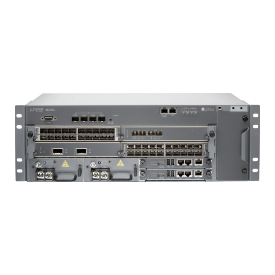
Juniper MX104 Hardware Manual (282 pages)
3D Universal Edge Router
Brand:
Juniper
| Category:
Network Router
| Size: 6.73 MB
Table of Contents
Table of Contents
3
About the Documentation
19
Documentation and Release Notes
19
Supported Platforms
19
Documentation Conventions
19
Table 1: Notice Icons
20
Table 2: Text and Syntax Conventions
20
Documentation Feedback
21
About the Documentation
21
Requesting Technical Support
22
Self-Help Online Tools and Resources
22
Opening a Case with JTAC
22
Chassis Components and Descriptions
25
Cooling System Components and Descriptions
25
Line Card Components and Descriptions
25
Power System Components and Descriptions
25
Overview
25
System Overview
25
Chapter 1 System Overview
27
System Overview
27
MX104 3D Universal Edge Router Overview
27
Figure 1: Front Panel of the MX104 Router
28
Figure 2: Rear View of the MX104 Router
28
MX104 Chassis Overview
28
Figure 3: Front View of the MX104 Router
29
System Overview
29
MX104 Hardware and CLI Terminology Mapping
30
Table 3: MX104 Routers Hardware Components and CLI Terminology
30
MX104 Component Redundancy
31
Chapter 2 Chassis Components and Descriptions
33
MX104 Alarm Contact Port Overview
33
Figure 4: Sample Output Alarm-Reporting Device
34
Table 4: Alarm Relay Contact Functions
34
MX104 Leds Overview
35
Alarm Leds on the Front Panel
35
Figure 5: Sample Input Alarm-Reporting Device
35
System LED on the Front Panel
36
Figure 6: Alarm Leds on the MX104 Router
36
Table 5: Alarm Leds on the Front Panel
36
Table 6: System LED on the Front Panel
36
MIC Leds
37
Power Supply LED
37
Routing Engine Leds
37
MX104 Leds Overview
37
Alarm Leds on the Front Panel
37
System LED on the Front Panel
38
Figure 7: Alarm Leds on the MX104 Router
38
Table 7: Alarm Leds on the Front Panel
38
Table 8: System LED on the Front Panel
38
MIC Leds
39
Power Supply LED
39
Routing Engine Leds
39
MX104 Leds Overview
39
Alarm Leds on the Front Panel
39
System LED on the Front Panel
40
Figure 8: Alarm Leds on the MX104 Router
40
Table 9: Alarm Leds on the Front Panel
40
Table 10: System LED on the Front Panel
40
MIC Leds
41
Power Supply LED
41
Routing Engine Leds
41
MX104 Clocking and Timing Ports Overview
41
Chapter 3 Cooling System Components and Descriptions
43
MX104 Cooling System and Airflow Overview
43
Figure 9: MX104 Fan Tray and Air Filter
43
Figure 10: Cooling System and Airflow in an MX104 Router
44
Chapter 4 Host Subsystem Components and Descriptions
45
MX104 Routing Engine Overview
45
Figure 11: MX104 Routing Engine
45
Router
45
MX104 Routing Engine Buttons
46
MX104 Routing Engine Components
46
MX104 Routing Engine Leds
47
Table 11: MX104 Routing Engine Buttons
47
Table 12: MX104 Routing Engine Leds
47
Table 13: Management Leds
47
MX104 Boot Sequence
48
MX104 Routing Engine Overview
48
MX104 Routing Engine Components
49
Figure 12: MX104 Routing Engine
49
MX104 Routing Engine Buttons
50
MX104 Routing Engine Leds
50
Table 14: MX104 Routing Engine Buttons
50
Table 15: MX104 Routing Engine Leds
50
MX104 Boot Sequence
51
MX104 Routing Engine Overview
51
Card that Allows You to Load Junos os
51
Hot-Insertable and Hot-Removable
51
Table 16: Management Leds
51
Figure 13: MX104 Routing Engine
52
MX104 Routing Engine Components
52
MX104 Routing Engine Buttons
53
MX104 Routing Engine Leds
53
Table 17: MX104 Routing Engine Buttons
53
Table 18: MX104 Routing Engine Leds
53
MX104 Boot Sequence
54
Routing Engine Specifications
54
Table 19: Management Leds
54
Table 20: Routing Engine Specifications
55
Table 21: End-Of-Life Routing Engine Specifications
56
Supported Routing Engines by Router
57
M7I Routing Engines
58
M10I Routing Engines
58
Table 22: M7I Routing Engines
58
M40E Routing Engines
59
M120 Routing Engines
59
Table 23: M10I Routing Engines
59
Table 24: M40E Routing Engines
59
Table 25: M120 Routing Engines
59
M320 Routing Engines
60
MX5, MX10, MX40, and MX80 Routing Engine
60
Table 26: M320 Routing Engines
60
MX104 Routing Engines
61
MX240 Routing Engines
61
Table 27: MX5, MX10, MX40, and MX80 Routing Engine
61
Table 28: MX104 Routing Engines
61
Table 29: MX240 Supported Routing Engines
61
MX480 Routing Engines
62
Table 30: MX480 Supported Routing Engines
62
MX960 Routing Engines
63
Table 31: MX960 Supported Routing Engines
63
MX2008 Routing Engines
64
MX2010 Routing Engines
64
MX2020 Supported Routing Engines
64
Table 32: MX2008 Supported Routing Engines
64
Table 33: MX2010 Supported Routing Engines
64
Table 34: MX2020 Supported Routing Engines
64
PTX3000 Routing Engines
65
PTX5000 Routing Engines
65
Table 35: PTX3000 Routing Engines
65
Table 36: PTX5000 Routing Engines
65
T320 Routing Engines
66
T640 Routing Engines
66
Table 37: T320 Routing Engines
66
Table 38: T640 Routing Engines
66
T1600 Routing Engines
67
Table 39: T1600 Routing Engines
67
T4000 Routing Engines
68
TX Matrix Routing Engines
68
Table 40: T4000 Routing Engines
68
Table
68
Name in CLI First Supported 32-Bit
68
Ethernet Interface Interface
68
TX Matrix Plus Routing Engines
69
TX Matrix Plus (with 3D Sibs) Routing Engines
69
Table 41: TX Matrix Routing Engines
69
Table 42: TX Matrix Plus Routing Engines
69
Table 43: Routing Engines on TX Matrix Plus with 3D Sibs
69
Fxp0 Fxp1
69
Chapter 5 Line Card Components and Descriptions
71
MX104 Modular Interface Card (MIC) Overview
71
Front-Pluggable Mics
71
Built-In 10-Gigabit Ethernet MIC
71
MIC Leds
73
Mics Supported by MX Series Routers
73
Table 44: SFP+ Port Leds
73
Table 45: Mics Supported by MX240, MX480, MX960, MX2008, MX2010, and MX2020 Routers
73
Line Card Components and Descriptions
75
Table 46: Mics Supported by MX5, MX10, MX40, MX80, and MX104 Routers
76
MX104 Port and Interface Numbering
77
Identifying Interface Numbers on the Hardware
77
Figure 14: MX104 Interface Port Mapping Example
78
Table 47: MX104 MIC Interface Names
78
Identifying Interface Numbers in the CLI
79
MX104 Modular Interface Card (MIC) Overview
82
Front-Pluggable Mics
82
Built-In 10-Gigabit Ethernet MIC
82
MIC Leds
84
Table 48: SFP+ Port Leds
84
Chapter 6 Power System Components and Descriptions
85
MX104 Power Overview
85
AC Power Supplies
85
DC Power Supplies
86
Power Supply Leds
86
Figure 15: AC Power Supply
86
Figure 16: DC Power Supply
86
MX104 Power Overview
87
Power System Components and Descriptions
87
Table 49: Power Supply LED
87
AC Power Supplies
88
DC Power Supplies
88
Figure 17: AC Power Supply
88
Figure 18: DC Power Supply
89
Power Supply Leds
89
Table 50: Power Supply LED
89
Preparation Overview
91
Transceiver and Cable Specifications
91
Port Cable and Pinout Specifications
91
Power Specifications
91
AC Power Specifications
91
DC Power Specifications
91
Site Planning, Preparation, and Specifications
91
Chapter 7 Preparation Overview
93
MX104 Router Environmental Specifications
94
Table 52: MX104 Environmental Specifications
94
Preparing the Site for the MX104 Router Overview
95
Rack Requirements for MX104 Routers
96
Table 53: Rack Requirements and Specifications for the Router
96
Cabinet Requirements for MX104 Routers
97
Table 54: Cabinet Requirements and Specifications for the MX104 Router
98
Clearance Requirements for Airflow and Hardware Maintenance on MX104
99
Figure 19: MX104 Chassis Dimensions and Clearance Requirements
99
Routers
100
MX104 Router Grounding Specifications
100
Grounding Points Specifications
100
Figure 20: Grounding Points on the MX104 Routers
100
Grounding Cable Lug Specifications
101
Figure 21: Grounding Cable Lug for MX104 AC Systems
101
Grounding Cable Specifications
102
Figure 22: Grounding Cable Lug for MX104 24 VDC Systems
102
Preparation Overview
93
MX104 Router Physical Specifications
93
Table 51: Physical Specifications of the MX104 Router Chassis
93
Chapter 8 Transceiver and Cable Specifications
103
Calculating Power Budget and Power Margin for Fiber-Optic Cables
103
Calculating Power Budget for Fiber-Optic Cable
103
Calculating Power Margin for Fiber-Optic Cable
104
Table 55: Estimated Values for Factors Causing Link Loss
104
Understanding Fiber-Optic Cable Signal Loss, Attenuation, and Dispersion
105
Signal Loss in Multimode and Single-Mode Fiber-Optic Cable
105
Attenuation and Dispersion in Fiber-Optic Cable
106
Chapter 9 Port Cable and Pinout Specifications
107
MX104 Clocking and Timing Ports Overview
107
MX104 Routing Engine Ethernet Port Specifications
108
Cable Specifications
108
Pinouts
108
Table 56: MX104 Routing Engine Ethernet Port Cable Specifications
108
Table 57: Ethernet Port Pinouts
108
MX104 Routing Engine Auxiliary and Console Ports Specifications
109
Cable Specifications
109
Pinouts
109
Port Cable and Pinout Specifications
109
Table 58: MX104 Routing Engine Console Port Cable Specifications
109
MX104 Routing Engine USB Port Specifications
110
Table 59: Console Port Pinouts
110
MX104 Alarm Contact Port Specifications
111
Cable Specifications
111
Port Pinouts
111
Table 60: MX104 Alarm Contact Port Cable Specifications
111
Table 61: Alarm Contact Connector Pinouts
111
MX104 BITS Port Specifications
113
Cable Specifications
113
Port Pinouts
113
Figure 23: RJ-48 Connector for MX104 BITS Ports
113
Table 62: MX104 BITS Port Cable Specifications
113
Table 63: BITS Port Pinouts
113
MX104 1-PPS and 10-Mhz GPS Port Specifications
114
MX104 Time of Day Port Specifications
114
Cable Specifications
114
Table 64: 1-PPS and 10-Mhz GPS Port Specifications
114
Port Pinouts
115
Table 65: TOD Cable Specifications
115
Table 66: Tod Port Connector Pinouts
115
Chapter 10 Power Specifications
117
Power Specifications
117
MX104 Power Consumption
117
Table 67: Power Consumed by MX104 Routers
117
AC Power Specifications
119
MX104 AC Power Specifications
119
Table 68: AC Power Electrical Specifications
119
Chapter 11 AC Power Specifications
119
MX104 AC Power Cord Specifications
120
Table 69: AC Power Cord Specifications
120
Chapter 12 DC Power Specifications
123
MX104 DC Power Cable and Lug Specifications
124
DC Power Cable Lug Specifications
124
DC Power Cable Specifications
124
Figure 24: DC Power Cable Lug
124
DC Power Specifications
123
MX104 DC Power Specifications
123
Table 70: DC Power Electrical Specifications
123
DC Power Specifications
125
Chapter 13 Unpacking the MX104 Router
127
Chapter 14 Installing the MX104 Router
127
Unpacking the MX104 Router
129
Unpacking an MX104 Router
129
Parts Inventory (Packing List) for an MX104 Router
130
Table 71: Parts List for a Fully Configured MX104 Router
130
Table 72: Accessory Box Parts List for an MX104 Router
131
Installing the MX104 Router
133
Installing and Connecting an MX104 Router Overview
133
Installing the MX104 Router in the Rack
134
Figure 25: Install the Front-Mounted Router in the Rack
135
Chapter 15 Connecting the MX104 Router to Power
137
Connecting the MX104 Router to Earth Ground
137
Connecting AC Power Cords to the MX104 Router
139
Figure 26: Grounding Points on the MX104 Router
139
Figure 27: Connecting AC Power to the Router
140
Connecting DC Power Cables to the MX104 Router
141
Figure 28: Connecting the Ground Cable to the MX104 DC Power Supply
142
Figure 29: Connecting DC Power to the Router
144
Chapter 16 Connecting the MX104 Router to the Network
145
Connecting the MX104 Router to Management Devices
145
Connecting the Router to a Network for Out-Of-Band Management
145
Figure 30: Ethernet Cable Connector
145
Connecting the Router to a Management Console Device
146
Figure 31: Ethernet Port
146
Figure 32: Routing Engine Console Cable Connector
146
Connecting the MX104 Router to External Clocking and Timing Devices
147
Connecting 1-PPS and 10-Mhz Timing Devices to the MX104 Router
147
Figure 33: Console Connections
147
Connecting a T1 or E1 External Clocking Device to the MX104 Router
148
Connecting a Time-Of-Day Device to the MX104 Router
148
Connecting the MX104 Router to an External Alarm-Reporting Device
148
Connecting Interface Cables to MX104 Routers
149
Figure 34: Attaching a Cable to a MIC
150
Chapter 17 Initially Configuring the MX104 Router
153
Chapter 22 Replacing Line Card Components
157
Chapter 23 Replacing Power System Components
157
Overview of Installing and Replacing Components
157
Overview of Installing and Replacing Components
159
MX104 Field-Replaceable Units (Frus)
159
Table 73: Field-Replaceable Units
159
Replacing Chassis Components
161
Replacing an MX104 Console or Auxiliary Cable
161
Removing an MX104 Console or Auxiliary Cable
161
Figure 35: Ethernet Cable Connectors
161
Installing an MX104 Console or Auxiliary Cable
162
Replacing an MX104 Management Ethernet Cable
162
Removing an MX104 Management Ethernet Cable
162
Figure 36: Ethernet Cable Connectors
162
Installing an MX104 Management Ethernet Cable
163
Replacing an MX104 Fiber-Optic Cable
163
Disconnecting an MX104 Fiber-Optic Cable
163
Connecting an MX104 Fiber-Optic Cable
164
Figure 37: Connecting a Fiber-Optic Cable to an Optical Transceiver Installed in
164
Replacing an MX104 Alarm Cable
165
Disconnecting the Router from an External Alarm-Reporting Device
165
Connecting the MX104 Router to an External Alarm-Reporting Device
165
Replacing Cooling System Component
167
Replacing an MX104 Air Filter
167
Removing an MX104 Air Filter
167
Installing an MX104 Air Filter
168
Figure 38: Removing the MX104 Air Filter
168
Installing an MX104 Air Filter
169
Figure 39: Installing the Air Filter
169
Replacing an MX104 Fan Tray
170
Removing an MX104 Fan Tray
170
Figure 40: Installing the Air Filter
170
Installing an MX104 Fan Tray
171
Figure 41: Removing the Fan Tray
171
Installing an MX104 Fan Tray
172
Figure 42: Installing the Fan Tray
172
Figure 43: Installing the Fan Tray
173
Replacing Host Subsystem Components
175
Installing an MX104 Routing Engine
175
Replacing an MX104 Routing Engine
176
Effect of Taking the MX104 Routing Engine Offline
176
Figure 44: Installing a Routing Engine
176
Replacing Host Subsystem Components
177
Table 74: Effect of Taking the Routing Engine Offline
177
Taking an MX104 Routing Engine Offline
178
Removing an MX104 Routing Engine
179
Installing an MX104 Routing Engine
180
Figure 45: Removing an MX104 Routing Engine
180
Figure 46: Installing a Routing Engine
181
Replacing Line Card Components
183
Installing an MX104 MIC
183
Replacing an MX104 MIC
185
Removing an MX104 MIC
185
Figure 47: Installing a MIC
185
Installing an MX104 MIC
187
Figure 48: Removing a MIC
187
Figure 49: Installing a MIC
188
Installing an MX104 Transceiver
189
Replacing an MX104 Transceiver
190
Removing an MX104 Transceiver
190
Installing an MX104 Transceiver
191
Figure 50: Removing Transceivers
191
Replacing Power System Components
193
Installing an MX104 AC Power Supply
193
Replacing an MX104 AC Power Supply
194
Removing an MX104 AC Power Supply
194
Figure 51: Installing an AC Power Supply
194
Figure 52: Removing an AC Power Cord
195
Installing an MX104 AC Power Supply
196
Figure 53: Removing an AC Power Supply
196
Installing an MX104 DC Power Supply
197
Figure 54: Installing an AC Power Supply
197
Figure 55: Connecting a DC Power Supply Grounding Cable
198
Figure 56: Installing a DC Power Supply
200
Figure 57: Connecting the DC Power Cables
200
Replacing an MX104 DC Power Supply
201
Removing an MX104 DC Power Supply
201
Figure 58: Disconnecting the DC Power Cables
202
Installing an MX104 DC Power Supply
203
Figure 59: Disconnecting the Grounding Cable
203
Figure 60: Removing a DC Power Supply
203
Figure 61: Connecting a DC Power Supply Grounding Cable
204
Figure 62: Installing a DC Power Supply
206
Figure 63: Connecting the DC Power Cables
206
Part 5 Maintaining the Chassis and Components
209
Chapter 18 Installing and Replacing Components
157
Chapter 21 Replacing Host Subsystem Components
157
Chapter 20 Replacing Cooling System Component
157
Chapter 19 Replacing Chassis Components
157
Chapter 24 Routine Maintenance Procedures
211
Routine Maintenance Procedures for the MX104 Router
211
Connecting the MX104 Router to Power
127
Connecting the MX104 Router to the Network
127
Initial Installation and Configuration
127
Chapter 25 Maintaining Components
213
Maintaining the MX104 Air Filter
214
Maintaining Cables that Connect to MX104 Network Ports
215
Maintaining the MX104 Mics and Network Ports
216
Maintaining the MX104 Routing Engines
216
Maintaining Components
213
Maintaining the MX104 Cooling System
213
Part 6 Troubleshooting Hardware
219
Troubleshooting Hardware
219
Troubleshooting Components
219
Chapter 26 Troubleshooting Components
221
Alarm Devices and Messages
222
Understanding Alarm Types and Severity Classes on MX104 Routers
222
Table 75: Alarm Terms
222
Alarm Severity Classes
223
Verifying Active Alarms on MX104 Routers
223
Monitoring System Log Messages on MX104 Routers
224
Table 76: Alarm Output Fields
224
Troubleshooting Components
221
Troubleshooting Resources for MX104 Routers
221
Command-Line Interface
221
Front Panel Leds
221
Contacting Customer Support and Returning the Chassis or Components
225
Locating Component Serial Numbers
225
Chapter 27 Contactingcustomersupport
227
Contacting Customer Support
227
Chapter 28 Locating Component Serial Numbers
229
Displaying MX104 Components and Serial Numbers
229
MX104 Chassis Serial Number Label
230
MX104 Fan Tray Serial Number Label
230
Figure 64: Serial Number ID Label
230
Figure 65: MX104 Chassis Serial Number Label
230
MX104 MIC Serial Number Label
231
Figure 66: MX104 Fan Tray Serial Number Label
231
Figure 67: MX104 MIC Serial Number Label
231
MX104 Power Supply Serial Number Label
232
MX104 Routing Engine Serial Number Label
232
Figure 68: MX104 Power Supply Serial Number Label
232
Figure 69: MX104 Routing Engine Serial Number Label
232
Chapter 29 Packing and Returning Components
233
Guidelines for Packing Hardware Components for Shipment
234
Packing the MX104 Router for Shipment
234
Packing and Returning Components
233
Returning a Hardware Component to Juniper Networks, Inc
233
Chapter 30 General Safety Guidelines and Warnings
237
Safety and Compliance Information
237
General Safety Guidelines and Warnings
239
Definition of Safety Warning Levels
239
General Safety Guidelines for Juniper Networks Devices
241
General Safety Warnings for Juniper Networks Devices
242
Qualified Personnel Warning
242
Restricted-Access Area Warning
242
Preventing Electrostatic Discharge Damage to an MX104 Router
244
Figure 70: ESD Point on the MX104 Router Chassis
244
Figure 71: Placing a Component into an Electrostatic Bag
245
Chapter 31 Fire Safety Requirements
247
Fire Safety Requirements for Juniper Networks Devices
247
General Fire Safety Requirements
247
Fire Suppression
247
Fire Suppression Equipment
247
Chapter 32 Installation Safety Guidelines and Warnings
249
Installation Safety Warnings for Juniper Networks Devices
249
Intrabuilding Ports Warning
249
Installation Instructions Warning
249
Rack-Mounting Requirements and Warnings
250
Ramp Warning
254
Chapter 33 Laser and LED Safety Guidelines and Warnings
255
General Laser Safety Guidelines for Juniper Networks Devices
255
Laser Safety Warnings for Juniper Networks Devices
255
Class 1 Laser Product Warning
256
Class 1 LED Product Warning
256
Laser Beam Warning
257
Radiation from Open Port Apertures Warning
257
Chapter 34 Maintenance and Operational Safety Guidelines and Warnings
259
Maintenance and Operational Safety Warnings for MX104 Routers
259
Battery Handling Warning
259
Jewelry Removal Warning
260
Lightning Activity Warning
261
Operating Temperature Warning
262
Product Disposal Warning
263
Chapter 35 Electrical Safety Guidelines and Warnings
265
In Case of an Electrical Accident
265
General Electrical Safety Warnings for Juniper Networks Devices
265
Grounded Equipment Warning
266
Grounding Requirements and Warning
266
Midplane Energy Hazard Warning
267
Multiple Power Supplies Disconnection Warning
267
Power Disconnection Warning
268
Devices
269
MX104 AC Power Electrical Safety Guidelines and Warnings
270
MX104 DC Power Electrical Safety Guidelines
271
DC Power Electrical Safety Warnings for Juniper Networks Devices
272
DC Power Copper Conductors Warning
272
DC Power Disconnection Warning
272
DC Power Wiring Terminations Warning
274
Site Electrical Wiring Guidelines for MX104 Routers
275
Distance Limitations for Signaling
275
Radio Frequency Interference
275
Electromagnetic Compatibility
275
Chapter 36 Agency Approvals and Compliance Statements
277
Agency Approvals for MX104 Routers
277
Compliance Statements for NEBS for MX104 Routers
278
Compliance Statements for EMC Requirements for MX104 Routers
279
Canada
279
European Community
279
Israel
279
Japan
280
United States
280
Compliance Statements for Environmental Requirements for Juniper Networks
280
Devices
280
Compliance Statements for Acoustic Noise for MX104 Routers
280
Advertisement
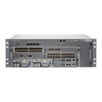
Juniper MX104 Hardware Manual (214 pages)
3D Universal Edge Router
Brand:
Juniper
| Category:
Network Router
| Size: 6.44 MB
Table of Contents
Table of Contents
3
About the Documentation
13
Documentation Conventions
13
Junos os Documentation and Release Notes
13
Table 1: Notice Icons
13
Table 2: Text and Syntax Conventions
14
Documentation Feedback
15
Requesting Technical Support
15
Self-Help Online Tools and Resources
15
About the Documentation
15
Opening a Case with JTAC
16
MX104 3D Universal Edge Router Overview
17
MX104 Hardware Components
17
MX104 Router Description
17
Chapter 1 MX104 Router Description
19
MX104 3D Universal Edge Router Overview
19
MX104 Hardware and CLI Terminology Mapping
20
Figure 1: Front Panel of the MX104 Router
20
Figure 2: Rear View of the MX104 Router
20
Table 3: MX104 Routers Hardware Components and CLI Terminology
20
MX104 Port and Interface Numbering
21
Identifying Interface Numbers on the Hardware
21
Table 13: Protocols and Applications Supported by MX104 Routers
21
Figure 3: MX104 Interface Port Mapping Example
22
Identifying Interface Numbers in the CLI
23
MX104 Router Description
23
Table 4: MX104 MIC Interface Names
23
Chapter 2 MX104 Hardware Components
27
MX104 Chassis Overview
27
MX104 Alarm Contact Port Overview
28
Figure 4: Front View of the MX104 Router
28
Figure 5: Sample Output Alarm-Reporting Device
29
MX104 Hardware Components
29
Table 5: Alarm Relay Contact Functions
29
Figure 6: Sample Input Alarm-Reporting Device
30
MX104 Clocking and Timing Ports Overview
30
Figure 7: MX104 Fan Tray and Air Filter
31
MX104 Cooling System and Airflow Overview
31
Figure 8: Cooling System and Airflow in an MX104 Router
32
Front-Pluggable Mics
32
MX104 Modular Interface Card (MIC) Overview
32
Built-In 10-Gigabit Ethernet MIC
33
MIC Leds
34
MX104 Power Overview
34
Table 6: SFP+ Port Leds
34
AC Power Supplies
35
DC Power Supplies
35
Figure 9: AC Power Supply
35
Figure 10: DC Power Supply
36
MX104 Routing Engine Overview
36
Power Supply Leds
36
Table 7: Power Supply LED
36
Figure 11: MX104 Routing Engine
37
MX104 Routing Engine Components
37
MX104 Routing Engine Buttons
38
MX104 Routing Engine Leds
38
Table 8: MX104 Routing Engine Buttons
38
Table 9: MX104 Routing Engine Leds
38
Alarm Leds on the Front Panel
39
MX104 Boot Sequence
39
MX104 Leds Overview
39
Table 10: Management Leds
39
Figure 12: Alarm Leds on the MX104 Router
40
System LED on the Front Panel
40
Table 11: Alarm Leds on the Front Panel
40
Table 12: System LED on the Front Panel
40
MIC Leds
41
Power Supply LED
41
Routing Engine Leds
41
Chapter 3 Protocols and Applications Supported by the Router
43
Protocols and Applications Supported by MX104 Routers
43
Protocols and Applications Supported by the Router
45
Setting up the MX104 Router
51
Preparing the Site for MX104 Router Installation
51
Installing the MX104 Router
51
Chapter 4 Preparing the Site for MX104 Router Installation
53
Preparing the Site for the MX104 Router Overview
53
Router
53
Rack Requirements for MX104 Routers
54
Cabinet Requirements for MX104 Routers
55
Preparing the Site for MX104 Router Installation
55
Table 14: Rack Requirements and Specifications for the Router
55
Clearance Requirements for Airflow and Hardware Maintenance on MX104
56
Table 15: Cabinet Requirements and Specifications for the MX104 Router
56
Figure 13: MX104 Chassis Dimensions and Clearance Requirements
57
Routers
57
Chapter 5 MX104 Router Installation Overview
59
Installing and Connecting an MX104 Router Overview
59
Chapter 6 Unpacking the MX104 Router
61
Parts Inventory (Packing List) for an MX104 Router
61
Table 16: Parts List for a Fully Configured MX104 Router
61
Table 17: Accessory Box Parts List for an MX104 Router
62
Unpacking an MX104 Router
63
Unpacking the MX104 Router
63
Chapter 7 Installing the MX104 Router
65
Installing the MX104 Router in the Rack
65
Figure 14: Install the Front-Mounted Router in the Rack
66
Chapter 8 Grounding and Providing Power to the MX104 Router
67
Connecting the MX104 Router to Earth Ground
67
Figure 15: Grounding Points on the MX104 Router
68
Connecting AC Power Cords to the MX104 Router
69
Connecting DC Power Cables to the MX104 Router
70
Figure 16: Connecting AC Power to the Router
70
Figure 17: Connecting the Ground Cable to the MX104 DC Power Supply
71
Figure 18: Connecting DC Power to the Router
73
Chapter 9 Connecting the MX104 Router to External Devices
75
Connecting the MX104 Router to Management Devices
75
Connecting the Router to a Network for Out-Of-Band Management
75
Figure 19: Ethernet Cable Connector
75
Connecting the Router to a Management Console Device
76
Figure 20: Ethernet Port
76
Figure 21: Routing Engine Console Cable Connector
76
Figure 22: Console Connections
76
Connecting the MX104 Router to External Clocking and Timing Devices
77
Connecting 1-PPS and 10-Mhz Timing Devices to the MX104 Router
77
Connecting a T1 or E1 External Clocking Device to the MX104 Router
77
Connecting a Time-Of-Day Device to the MX104 Router
78
Connecting the MX104 Router to an External Alarm-Reporting Device
78
Connecting Interface Cables to MX104 Routers
79
Connecting the MX104 Router to External Devices
79
Figure 23: Attaching a Cable to a MIC
80
Chapter 10 Configuring Junos os
81
Initially Configuring the MX104 Router
81
Hardware Maintenance, Troubleshooting, and Replacement Procedures
85
Replacing MX104 Hardware Components
85
Chapter 11 Maintaining MX104 Router Hardware Components
87
Routine Maintenance Procedures for the MX104 Router
87
Maintaining Cables that Connect to MX104 Network Ports
87
Maintaining the MX104 Mics and Network Ports
89
Maintaining the MX104 Cooling System
89
MX104 3D Universal Edge Router Overview
89
Maintaining the MX104 Air Filter
90
Maintaining the MX104 Power System
91
Maintaining the MX104 Routing Engines
92
Chapter 12 Troubleshooting MX104 Hardware Components
95
Troubleshooting Resources for MX104 Routers
95
Command-Line Interface
95
Front Panel Leds
95
Router
95
Alarm Devices and Messages
96
Understanding Alarm Types and Severity Classes on MX104 Routers
96
Table 18: Alarm Terms
96
Alarm Severity Classes
97
Verifying Active Alarms on MX104 Routers
97
Troubleshooting MX104 Hardware Components
97
Table 19: Alarm Output Fields
97
Monitoring System Log Messages on MX104 Routers
98
Chapter 13 Replacing MX104 Hardware Components
99
MX104 Field-Replaceable Units (Frus)
99
Replacing MX104 Cables
100
Disconnecting the Router from an External Alarm-Reporting Device
100
Replacing an MX104 Alarm Cable
100
Table 20: Field-Replaceable Units
100
Device
101
Removing an MX104 Clocking or Timing Cable
101
Replacing an MX104 Clocking or Timing Cable
101
Replacing MX104 Hardware Components
101
Figure 24: Ethernet Cable Connectors
102
Installing an MX104 Clocking or Timing Cable
102
Installing an MX104 Console or Auxiliary Cable
102
Removing an MX104 Console or Auxiliary Cable
102
Replacing an MX104 Console or Auxiliary Cable
102
Disconnecting an MX104 Fiber-Optic Cable
103
Figure 25: Ethernet Cable Connectors
103
Installing an MX104 Management Ethernet Cable
103
Removing an MX104 Management Ethernet Cable
103
Replacing an MX104 Fiber-Optic Cable
103
Replacing an MX104 Management Ethernet Cable
103
Connecting an MX104 Fiber-Optic Cable
104
Replacing an MX104 Air Filter
105
Figure 26: Connecting a Fiber-Optic Cable to an Optical Transceiver Installed in
105
Removing an MX104 Air Filter
105
Figure 27: Removing the MX104 Air Filter
106
Installing an MX104 Air Filter
106
Replacing an MX104 Fan Tray
107
Figure 28: Installing the Air Filter
107
Removing an MX104 Fan Tray
107
Figure 29: Removing the Fan Tray
108
Figure 30: Installing the Fan Tray
108
Installing an MX104 Fan Tray
108
Replacing an MX104 MIC
109
Removing an MX104 MIC
109
Figure 31: Removing a MIC
110
Installing an MX104 MIC
110
Figure 32: Installing a MIC
111
Replacing an MX104 AC Power Supply
112
Removing an MX104 AC Power Supply
112
Figure 33: Removing an AC Power Cord
113
Figure 34: Removing an AC Power Supply
113
Installing an MX104 AC Power Supply
113
Replacing an MX104 DC Power Supply
114
Figure 35: Installing an AC Power Supply
114
Removing an MX104 DC Power Supply
114
Figure 36: Disconnecting the DC Power Cables
116
Figure 37: Disconnecting the Grounding Cable
116
Figure 38: Removing a DC Power Supply
116
Installing an MX104 DC Power Supply
117
Figure 39: Connecting a DC Power Supply Grounding Cable
118
Figure 40: Installing a DC Power Supply
119
Replacing an MX104 Routing Engine
120
Effect of Taking the MX104 Routing Engine Offline
120
Figure 41: Connecting the DC Power Cables
120
Table 21: Effect of Taking the Routing Engine Offline
121
Taking an MX104 Routing Engine Offline
122
Removing an MX104 Routing Engine
123
Figure 42: Removing an MX104 Routing Engine
124
Installing an MX104 Routing Engine
124
Figure 43: Installing a Routing Engine
125
Removing an MX104 Transceiver
125
Replacing an MX104 Transceiver
125
Figure 44: Removing Transceivers
126
Installing an MX104 Transceiver
127
Appendixes
129
Appendix A Safety and Regulatory Compliance Information for the MX104 Router
129
Appendix D Power Guidelines, Requirements, and Specifications for the MX104
129
Appendix A Safety and Regulatory Compliance Information for the MX104 Router
131
Definition of Safety Warning Levels
131
Safety Guidelines and Warnings
133
General Safety Guidelines for Juniper Networks Devices
133
General Safety Warnings for Juniper Networks Devices
134
Qualified Personnel Warning
134
Restricted Access Area Warning
134
Preventing Electrostatic Discharge Damage to an MX104 Router
136
Fire Safety Requirements for Juniper Networks Devices
137
Figure 45: ESD Point on the MX104 Router Chassis
137
Figure 46: Placing a Component into an Electrostatic Bag
137
General Fire Safety Requirements
137
Fire Suppression
138
Fire Suppression Equipment
138
Installation Safety Warnings for Juniper Networks Devices
138
Installation Instructions Warning
139
Intra-Building Ports Warning
139
Rack-Mounting Requirements and Warnings
139
Ramp Warning
143
MX104 Router Chassis Lifting Guidelines
143
General Laser Safety Guidelines for Juniper Networks Devices
144
Laser Safety Warnings for Juniper Networks Devices
144
Class 1 Laser Product Warning
145
Class 1 LED Product Warning
145
Laser Beam Warning
146
Radiation from Open Port Apertures Warning
146
Maintenance and Operational Safety Warnings for MX104 Routers
147
Battery Handling Warning
147
Jewelry Removal Warning
148
Lightning Activity Warning
150
Operating Temperature Warning
150
Product Disposal Warning
151
General Electrical Safety Guidelines and Warnings
152
General Electrical Safety Warnings for Juniper Networks Devices
152
General Electrical Safety Guidelines and Electrical Codes for Juniper Networks Devices
156
In Case of an Electrical Accident
157
MX104 AC Power Electrical Safety Guidelines and Warnings
157
MX104 DC Power Electrical Safety Guidelines
158
DC Power Electrical Safety Warnings for Juniper Networks Devices
159
Site Electrical Wiring Guidelines for MX Series Routers
162
Agency Approvals and Compliance Statements
163
Agency Approvals for MX104 Routers
163
Compliance Statements for NEBS for MX104 Routers
165
Compliance Statements for EMC Requirements for MX104 Routers
165
Canada
165
European Community
165
Declaration of Conformity
166
Figure 47: MX104 Declaration of Conformity
166
Israel
166
Japan
167
United States
167
Compliance Statements for Environmental Requirements for Juniper Networks Devices
167
Compliance Statements for Acoustic Noise for MX104 Routers
167
Appendix Bmx104 Router Physical Specifications
169
MX104 Router Physical Specifications
169
Table 22: Physical Specifications of the MX104 Router Chassis
169
Appendix Cmx104 Router Environmental Specifications
171
MX104 Router Environmental Specifications
171
Table 23: MX104 Environmental Specifications
171
Appendix D Power Guidelines, Requirements, and Specifications for the MX104
173
Router
173
MX104 Router Grounding Specifications
173
Grounding Points Specifications
173
Grounding Cable Lug Specifications
174
Figure 48: Grounding Points on the MX104 Routers
174
Grounding Cable Specifications
175
MX104 AC Power Specifications
175
Figure 49: Grounding Cable Lug
175
Table 24: AC Power Electrical Specifications
175
MX104 AC Power Cord Specifications
176
Table 25: AC Power Cord Specifications
177
MX104 DC Power Specifications
178
Table 26: DC Power Electrical Specifications
178
MX104 DC Power Cable and Lug Specifications
179
DC Power Cable Lug Specifications
179
Figure 50: DC Power Cable Lug
179
DC Power Cable Specifications
180
MX104 Power Consumption
180
Power Requirements for MX104 Components
180
Table 27: Power Consumed by MX104 Routers
180
Calculating Power Requirements for MX104 Routers
181
Table 28: MX104 FRU Power Requirements
181
Table 29: Sample Power Requirements for an MX104 Router
182
Table 30: Calculating Input Power Example
182
Table 31: Calculating Thermal Output
183
Appendix E Cable and Wire Guidelines for the MX104 Router
185
Understanding Fiber-Optic Cable Signal Loss, Attenuation, and Dispersion
185
Signal Loss in Multimode and Single-Mode Fiber-Optic Cable
185
Attenuation and Dispersion in Fiber-Optic Cable
185
Calculating Power Budget and Power Margin for Fiber-Optic Cables
186
Calculating Power Budget for Fiber-Optic Cable
186
Calculating Power Margin for Fiber-Optic Cable
187
Cable and Wire Guidelines for the MX104 Router
187
Table 32: Estimated Values for Factors Causing Link Loss
187
Appendix Fmx104 Cable Connector Specifications
189
MX104 Alarm Contact Port Specifications
189
Cable Specifications
189
Port Pinouts
189
Table 33: MX104 Alarm Contact Port Cable Specifications
189
Table 34: Alarm Contact Connector Pinouts
190
MX104 BITS Port Specifications
191
Cable Specifications
191
Port Pinouts
191
Table 35: MX104 BITS Port Cable Specifications
191
Table 36: BITS Port Pinouts
191
MX104 1-PPS and 10-Mhz GPS Port Specifications
192
MX104 Time of Day Port Specifications
192
Cable Specifications
192
Table 37: 1-PPS and 10-Mhz GPS Port Specifications
192
Port Pinouts
193
MX104 Routing Engine Ethernet Port Specifications
193
Table 38: TOD Cable Specifications
193
Table 39: Tod Port Connector Pinouts
193
Cable Specifications
194
Pinouts
194
Table 40: MX104 Routing Engine Ethernet Port Cable Specifications
194
Table 41: Ethernet Port Pinouts
194
MX104 Routing Engine Auxiliary and Console Ports Specifications
195
Cable Specifications
195
Pinouts
195
MX104 Cable Connector Specifications
195
Table 42: MX104 Routing Engine Console Port Cable Specifications
195
Table 43: Console Port Pinouts
195
MX104 Routing Engine USB Port Specifications
196
Appendix G Contacting Customer Support and Returning MX104 Hardware
197
Displaying MX104 Components and Serial Numbers
197
MX104 Chassis Serial Number Label
198
MX104 Fan Tray Serial Number Label
198
Figure 51: Serial Number ID Label
198
Figure 52: MX104 Chassis Serial Number Label
198
MX104 MIC Serial Number Label
199
Figure 53: MX104 Fan Tray Serial Number Label
199
Figure 54: MX104 MIC Serial Number Label
199
MX104 Power Supply Serial Number Label
200
MX104 Routing Engine Serial Number Label
200
Figure 55: MX104 Power Supply Serial Number Label
200
Figure 56: MX104 Routing Engine Serial Number Label
200
Contacting Customer Support
201
Returning a Hardware Component to Juniper Networks, Inc
201
Packing the MX104 Router for Shipment
202
Guidelines for Packing Router Components for Shipment
203
Index
205
Index
207
Juniper MX104 Quick Start Manual (30 pages)
niversal Routing Platforms
Brand:
Juniper
| Category:
Network Hardware
| Size: 1.79 MB
Table of Contents
Table of Contents
1
MX104 Quick Start Description
3
Step 1: Prepare the Site for MX104 Router Installation
5
Step 2: Install the Router
7
Tools Required to Install the Router in a Rack
7
Install the MX104 Router in the Rack
7
Step 3: Ground the MX104 Router
9
Tools Required to Ground the MX104 Router
9
Connect the Grounding Cable
9
Step 4: Connect External Devices and Cables
12
Connect the Router to a Network for Out-Of-Band Management
12
Connect the Router to a Management Console Device
12
Connect MIC Cables to the MX104 Router
13
Step 5: Connect Power to the MX104 Router
15
Connect AC Power to an AC-Powered MX104 Router
15
Connect DC Power to a DC-Powered MX104 Router
16
Step 6: Perform Initial Software Configuration
21
Enter Configuration Mode
21
Configure User Accounts and Passwords
22
Configure System Attributes
22
Commit the Configuration
23
Safety Warnings
25
Compliance Statements for NEBS
26
Compliance Statements for EMC Requirements
27
Canada
27
European Community
27
Israel
27
Japan
28
United States
28
Junos os Documentation and Release Notes
29
Requesting Technical Support
29
Self-Help Online Tools and Resources
29
Creating a Service Request with JTAC
30
Revision History
30
Advertisement
Advertisement
Related Products
Juniper MX10
Juniper MX10008
Juniper Networks MX150
Juniper MX10003
Juniper MX10004-BASE
Juniper MX10004-PREMIUM
Juniper MX10004-3F-BASE
Juniper MX10004-4F-PREM
Juniper MX2020
Juniper MX80
Juniper Categories
Network Router
Switch
Gateway
Software
Network Hardware
More Juniper Manuals
Login
Sign In
OR
Sign in with Facebook
Sign in with Google
Upload manual
Upload from disk
Upload from URL