Sign In
Upload
Manuals
Brands
Juniper Manuals
Network Router
MX80
Juniper MX80 Manuals
Manuals and User Guides for Juniper MX80. We have
3
Juniper MX80 manuals available for free PDF download: Hardware Manual, Quick Start Manual, Datasheet
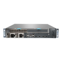
Juniper MX80 Hardware Manual (180 pages)
Universal Routing Platform
Brand:
Juniper
| Category:
Network Router
| Size: 4.39 MB
Table of Contents
Table of Contents
3
About the Documentation
13
Documentation and Release Notes
13
Using the Examples in this Manual
13
Merging a Full Example
14
Merging a Snippet
14
About the Documentation
15
Documentation Conventions
15
Table 1: Notice Icons
15
Table 2: Text and Syntax Conventions
16
Documentation Feedback
17
Requesting Technical Support
17
Creating a Service Request with JTAC
18
Self-Help Online Tools and Resources
18
Benefits of the MX5, MX10, MX40, and MX80 Router
19
MX5, MX10, MX40, and MX80 Router Overview
19
Overview
19
System Overview
19
MX5, MX10, MX40, and MX80 Hardware Overview
20
Figure 1: MX5 Router
21
Figure 2: MX10 Router
21
Figure 3: MX40 Router
21
Figure 4: MX80 Router
22
MX5, MX10, MX40, and MX80 Router Models
22
Table 3: MX5 Router Models
22
Table 4: MX10 Router Models
22
Table 5: MX40 Router Models
23
Table 6: MX80 Router Models
23
Table 7: MX5, MX10, MX40, and MX80 Routers Hardware Components and CLI
23
Terminology
23
MX5, MX10, MX40, and MX80 Chassis
24
MX5, MX10, MX40, and MX80 Chassis Description
24
Figure 5: Front View of the MX5 Router
25
Figure 6: Front View of the MX10 Router
25
Figure 7: Front View of the MX40 Router
25
Figure 10: Rear View of the MX5, MX10, MX40, and MX80 Routers
26
Figure 8: Front View of the MX80 Router (Fixed Chassis)
26
Figure 9: Front View of the MX80 Router (Modular Chassis)
26
MX5, MX10, MX40, and MX80 Baseboard Description
26
Baseboard Components
27
MX5, MX10, MX40, and MX80 Cable Management Bracket Description
27
Figure 11: Cable Management Bracket for the MX5, MX10, MX40, and MX80
28
Figure 12: Front Panel on the Fixed MX80 Router
28
MX5, MX10, MX40, and MX80 Front Panel Description
28
Figure 13: Front Panel on the Modular MX5, MX10, MX40, and MX80 Routers
29
Front Panel Components
29
Alarm Leds on the MX5, MX10, MX40, and MX80 Front Panel
30
Component Leds on the MX5, MX10, MX40, and MX80 Front Panel
30
Figure 14: USB Memory Device in an MX5, MX10, MX40, and MX80 Router
30
Link Leds on the Front Panel
30
Table 8: Alarm Leds on the MX5, MX10, MX40, and MX80 Front Panel
30
MX5, MX10, MX40, and MX80 Power System
31
Routing Engine LED on the Front Panel
31
System LED on the Front Panel
31
Table 10: Routing Engine LED on the Front Panel
31
Table 11: System LED on the Front Panel
31
Table 9: Link Leds on the Front Panel
31
MX5, MX10, MX40, and MX80 Power System Description
32
AC Power Supply Description
33
Figure 15: AC Power Supplies Installed in an MX5, MX10, MX40, and MX80
33
Figure 16: DC Power Supplies Installed in an MX5, MX10, MX40, and MX80
33
DC Power Supply Description
34
Figure 17: AC Power Supply
34
Figure 18: DC Power Supply
34
MX5, MX10, MX40, and MX80 Power Supply LED
34
MX5, MX10, MX40, and MX80 Routers AC Power Specifications
35
Power Consumption for an AC-Powered MX5, MX10, MX40, and MX80
35
Router
35
Table 12: Power Supply LED
35
Table 13: AC Power System Electrical Specifications
35
Table 14: AC Power Supply Electrical Specifications
35
Table 15: AC Base Router Power Requirements for the Fixed MX5, MX10, MX40, and MX80 Routers
36
Table 16: AC Base Router Power Requirements for the Modular MX5, MX10, MX40, and MX80 Routers
36
Table 17: Component Power Requirements
36
AC Power Cord Specifications for MX5, MX10, MX40, and MX80 Routers
37
MX80 Router
37
Table 18: AC Power Cord Specifications
37
MX5, MX10, MX40, and MX80 Routers DC Power Specifications
39
Power Consumption for a DC-Powered MX5, MX10, MX40, and MX80 Router
39
Router
39
Table 19: DC Power System Electrical Specifications
39
Table 20: DC Power Supply Electrical Specifications
39
Table 21: DC-Powered Base Router Power Requirements for the Fixed MX80
40
Table 22: DC-Powered Base Router Power Requirements for the MX5, MX10
40
Table 23: Component Power Requirements for DC-Powered Routers
40
DC Power Cable Specifications for MX5, MX10, MX40, and MX80 Routers
41
DC Power Source Cabling for MX5, MX10, MX40, and MX80 Routers
41
MX80 Routers
41
Routers
41
DC Power Cable Lug Specifications
42
DC Power Cable Specifications
42
Figure 19: DC Power Cable Lug
42
MX5, MX10, MX40, and MX80 Host Subsystem
42
MX5, MX10, MX40, and MX80 Routing Engine Description
42
Figure 20: Mics Installed in an MX5, MX10, MX40, and MX80 Router
43
Front-Pluggable Mics
43
MX5, MX10, MX40, and MX80 Interface Modules
43
MX5, MX10, MX40, and MX80 Modular Interface Card Description
43
MX5, MX10, MX40, and MX80 Routing Engine LED
43
Fixed (Built-In) Mics
44
Mics Supported by MX Series Routers
46
Table 24: Mics Supported by MX240, MX480, MX960 and MX2008 Routers
46
Table 25: Mics Supported by MX2010 and MX2020 Routers
48
Table 26: Mics Supported by MX5, MX10, and MX40 Routers
50
Table 27: Mics Supported by MX80 and MX104 Routers
52
Table 28: Mics Supported by MX10003 Router
53
MX5, MX10, MX40, and MX80 Port and Interface Numbering
54
Routers
54
Figure 21: MX5, MX10, MX40, and MX80 Interface Port Mapping
55
Table 29: MX5, MX10, MX40, and MX80 Components and Their Interface
55
Figure 22: MX80-48T Interface Port Mapping
56
Port and Interface Numbering on MX80-48T Routers
56
Table 30: MX80-48T Components and Interface Names
56
MX5, MX10, MX40, and MX80 Modular Interface Card Leds
57
Table 31: Tri-Rate MIC Leds
57
Chapter 2 Site Planning, Preparation, and Specifications
59
MX5, MX10, MX40, and MX80 Site Preparation Checklist
59
Table 32: MX80 Site Preparation Checklist
59
MX5, MX10, MX40, and MX80 Site Guidelines and Requirements
61
MX5, MX10, MX40, and MX80 Routers Physical Specifications
61
Table 33: MX5, MX10, MX40, and MX80 Physical Specifications
61
MX5, MX10, MX40, and MX80 Router Environmental Specifications
62
MX5, MX10, MX40, and MX80 Router Grounding Specifications
62
Grounding Points Specifications
62
Table 34: Router Environmental Specifications
62
Grounding Cable Lug Specifications
63
Grounding Cable Specifications
63
Figure 23: Grounding Points on MX5, MX10, MX40, and MX80 Routers
63
Figure 24: Grounding Cable Lug
63
MX5, MX10, MX40, and MX80 Rack Requirements
64
Table 35: MX5, MX10, MX40, and MX80 Rack Requirements and
64
MX5, MX10, MX40, and MX80 Routers Clearance Requirements for Airflow and Hardware Maintenance
65
Figure 25: Typical Open-Frame Rack
65
MX5, MX10, MX40, and MX80 Routers Cabinet Requirements and Specifications
66
Figure 26: MX5, MX10, MX40, and MX80 Chassis Dimensions and Clearance
66
Table 36: Cabinet Requirements and Specifications for an MX5, MX10, MX40
66
MX5, MX10, MX40, and MX80 Network Cable and Transceiver Planning
67
Determining Transceiver Support and Specifications for M Series and T
67
Figure 27: Airflow through Chassis
67
Series Routers
68
Dispersion
68
Signal Loss in Multimode and Single-Mode Fiber-Optic Cable
68
Attenuation and Dispersion in Fiber-Optic Cable
69
Calculating Power Budget and Power Margin for Fiber-Optic Cables
69
Calculating Power Budget for Fiber-Optic Cable
70
Calculating Power Margin for Fiber-Optic Cable
70
Table 37: Estimated Values for Factors Causing Link Loss
70
Routing Engine Interface Cable Specifications for MX5, MX10, MX40, and MX80 Routers
71
Table 38: Cable Specifications for Routing Engine Management
71
And Pinouts
72
Connector Pinouts for the aux and CONSOLE Ports on MX5, MX10, MX40, and MX80 Routers
72
Table 39: RJ-45 Connector Pinout for the aux and CONSOLE Ports
72
RJ-45 Connector Pinouts for the ETHERNET Port on MX5, MX10, MX40, and MX80 Routers
73
Table 40: RJ-45 Connector Pinout for the Routing Engine ETHERNET Port
73
Chapter 3 Initial Installation and Configuration
75
MX5, MX10, MX40, and MX80 Installation Summary
75
Unpacking and Mounting the MX5, MX10, MX40, and MX80
76
Tools and Parts Required to Unpack MX5, MX10, MX40, and MX80
76
Routers
76
Unpacking MX5, MX10, MX40, and MX80 Routers
76
Verifying the MX5, MX10, MX40, and MX80 Routers Parts Received
77
Table 41: Parts List for a Fully Configured Router
77
Table 42: Accessory Box Parts List
78
Installing the MX5, MX10, MX40, and MX80 Cable Management Bracket
79
MX80 Routers
79
Figure 28: Installing the Cable Management Bracket
79
Tools Required to Install MX5, MX10, MX40, and MX80 Chassis in the Rack
80
Figure 29: Front-Mounting the Brackets on MX5, MX10, MX40, and MX80
80
Figure 30: Center-Mounting the Brackets on MX5, MX10, MX40, and MX80
80
Installing MX5, MX10, MX40, and MX80 Chassis in the Rack
81
Connecting the MX5, MX10, MX40, and MX80 Routers to Power
82
Figure 31: Installing the Front-Mounted Router in the Rack
82
Figure 32: Installing the Center-Mounted Router in the Rack
82
Tools and Parts Required for MX5, MX10, MX40, and MX80 Router Grounding and Power Connections
83
Grounding MX5, MX10, MX40, and MX80 Routers
83
Router
84
Figure 33: Grounding Points on MX5, MX10, MX40, and MX80 Routers
84
Powering on an AC-Powered MX5, MX10, MX40, and MX80 Router
85
Router
86
Powering on a DC-Powered MX5, MX10, MX40, and MX80 Router
88
Figure 34: Connecting DC Power to the Router
88
Powering off MX5, MX10, MX40, and MX80 Routers
90
Connecting MX5, MX10, MX40, and MX80 Routers to Management Devices
91
Connecting the Router to a Network for Out-Of-Band Management
91
Connecting the Router to a Management Console or Auxiliary Device
91
Figure 35: Routing Engine Ethernet Cable Connector
91
Figure 36: Ethernet Port
91
Figure 37: Routing Engine Console and Auxiliary Cable Connector
92
Figure 38: Auxiliary and Console Ports
92
Initially Configuring MX5, MX10, MX40, and MX80 Routers
93
Chapter 4 Maintaining Components
97
Maintaining MX5, MX10, MX40, and MX80 Components
97
Tools and Parts Required to Maintain MX5, MX10, MX40, and MX80
97
Routers
97
Routine Maintenance Procedures for MX5, MX10, MX40, and MX80
97
Maintaining the MX5, MX10, MX40, and MX80 Routing Engine
97
Maintaining the MX5, MX10, MX40, and MX80 Air Filter
98
Replacing an MX5, MX10, MX40, and MX80 Air Filter
99
Removing an MX5, MX10, MX40, and MX80 Air Filter
99
Installing an MX5, MX10, MX40, and MX80 Air Filter
100
Figure 39: Removing the Air Filter
100
Maintaining the MX5, MX10, MX40, and MX80 Fan Tray
101
Figure 40: Installing the Air Filter
101
Replacing an MX5, MX10, MX40, and MX80 Fan Tray
102
Removing an MX5, MX10, MX40, and MX80 Fan Tray
102
Installing an MX5, MX10, MX40, and MX80 Fan Tray
103
Maintaining the MX5, MX10, MX40, and MX80 Mics and Transceivers
103
Maintaining the MX5, MX10, MX40, and MX80 Mics
103
Figure 41: Removing the Fan Tray
103
Figure 42: Installing the Fan Tray
103
Replacing an MX5, MX10, MX40, and MX80 MIC
104
Removing an MX5, MX10, MX40, and MX80 MIC
104
Installing an MX5, MX10, MX40, and MX80 MIC
106
Figure 43: Removing a MIC
106
Figure 44: Removing a Dual-Wide MIC
106
Figure 45: Installing the Septum
107
Figure 46: Installing a MIC
108
Installing an MX10, MX40, MX80, and MX104 Dual-Wide MIC
109
Figure 47: Removing the Septum
109
Replacing an MX5, MX10, MX40, and MX80 SFP or XFP Transceiver
111
Removing an MX5, MX10, MX40, and MX80 Transceiver
111
Figure 48: Installing a Dual-Wide MIC
111
Installing an MX5, MX10, MX40, and MX80 Transceiver
112
Figure 49: Removing Sfps or Xfps
112
Maintaining Cables that Connect to MX5, MX10, MX40, and MX80 Mics
113
Maintaining the MX5, MX10, MX40, and MX80 Power Supplies and Cables
114
Maintaining the MX5, MX10, MX40, and MX80 Power Supplies
114
Replacing an MX5, MX10, MX40, and MX80 AC Power Supply
115
Removing an MX5, MX10, MX40, and MX80 AC Power Supply
115
Installing an MX5, MX10, MX40, and MX80 AC Power Supply
116
Figure 50: Removing an AC Power Supply
116
Replacing an MX5, MX10, MX40, and MX80 AC Power Supply Cord
117
Disconnecting an MX5, MX10, MX40, and MX80 AC Power Supply
117
Cord
117
Connecting an MX5, MX10, MX40, and MX80 AC Power Supply
117
Figure 51: Installing an AC Power Supply
117
Cord
118
Replacing an MX5, MX10, MX40, and MX80 DC Power Supply
118
Removing an MX5, MX10, MX40, and MX80 DC Power Supply
118
Installing an MX5, MX10, MX40, and MX80 DC Power Supply
120
Figure 52: Removing a DC Power Supply
120
Figure 53: Disconnecting the DC Power Cables
120
Replacing an MX5, MX10, MX40, and MX80 DC Power Supply Cable
122
Disconnecting an MX5, MX10, MX40, and MX80 DC Power Supply
122
Figure 54: Installing a DC Power Supply
122
Figure 55: Connecting the DC Power Cables
122
Cable
124
Connecting an MX5, MX10, MX40, and MX80 DC Power Supply
124
Figure 56: Connecting Power Cables to the DC Power Supply
125
Troubleshooting Hardware
127
Troubleshooting the MX5, MX10, MX40, and MX80
127
Troubleshooting Resources for MX5, MX10, MX40, and MX80 Routers
127
Command-Line Interface
127
Chassis and Interface Alarm Messages
127
Front Panel Leds
128
Component Leds
128
Troubleshooting the MX5, MX10, MX40, and MX80 Fan Tray
129
Troubleshooting the MX5, MX10, MX40, and MX80 Mics
130
Troubleshooting the MX5, MX10, MX40, and MX80 Power Supplies
130
Components
133
Contacting Customer Support and Returning the Chassis or Components
133
Returning a Hardware Component to Juniper Networks, Inc
133
Numbers
134
MX5, MX10, MX40, and MX80 Chassis Serial Number Label
135
MX5, MX10, MX40, and MX80 Fan Tray Serial Number Label
135
Figure 57: Serial Number ID Label
135
Figure 58: MX5, MX10, MX40, and MX80 Chassis Serial Number Label
135
Figure 59: MX5, MX10, MX40, and MX80 Fan Tray Serial Number Label
135
MX5, MX10, MX40, and MX80 MIC Serial Number Label
136
Figure 60: 20-Port MIC Serial Number Label
136
Figure 61: 40-Port MIC Serial Number Label
136
MX5, MX10, MX40, and MX80 Power Supply Serial Number Label
137
Figure 62: 2-Port MIC Serial Number Label
137
Figure 63: Power Supply Serial Number Label
137
Contacting Customer Support to Obtain Return Material Authorization
138
Guidelines for Packing Hardware Components for Shipment
138
Packing MX5, MX10, MX40, and MX80 Routers for Shipment
139
Safety and Compliance Information
141
Definition of Safety Warning Levels
141
General Safety Guidelines for Juniper Networks Devices
143
General Safety Warnings for Juniper Networks Devices
144
Qualified Personnel Warning
144
Restricted-Access Area Warning
145
Preventing Electrostatic Discharge Damage to an MX5, MX10, MX40, and MX80
146
Router
146
Fire Safety Requirements for Juniper Networks Devices
147
General Fire Safety Requirements
147
Figure 64: ESD Points on the MX5, MX10, MX40, and MX80 Chassis
147
Figure 65: Placing a Component into an Electrostatic Bag
147
Fire Suppression
148
Fire Suppression Equipment
148
MX5, MX10, MX40 and MX80 Chassis Lifting Guidelines
149
Installation Safety Warnings for Juniper Networks Devices
149
Intrabuilding Ports Warning
149
Installation Instructions Warning
150
Rack-Mounting Requirements and Warnings
150
Ramp Warning
154
General Laser Safety Guidelines for Juniper Networks Devices
154
Laser Safety Warnings for Juniper Networks Devices
155
Class 1 Laser Product Warning
155
Class 1 LED Product Warning
155
Laser Beam Warning
156
Radiation from Open Port Apertures Warning
157
Maintenance and Operational Safety Warnings for Juniper Networks Devices
158
Battery Handling Warning
158
Jewelry Removal Warning
159
Lightning Activity Warning
160
Operating Temperature Warning
161
Product Disposal Warning
162
In Case of an Electrical Accident
163
General Electrical Safety Warnings for Juniper Networks Devices
163
Grounded Equipment Warning
163
Grounding Requirements and Warning
164
Midplane Energy Hazard Warning
165
Multiple Power Supplies Disconnection Warning
165
Power Disconnection Warning
166
Devices
167
MX80 Routers
167
DC Power Electrical Safety Warnings for Juniper Networks Devices
168
DC Power Copper Conductors Warning
168
DC Power Disconnection Warning
169
DC Power Wiring Terminations Warning
170
MX5, MX10, MX40, and MX80 DC Power Electrical Safety Guidelines
172
Site Electrical Wiring Guidelines for MX Series Routers
173
Distance Limitations for Signaling
173
Radio Frequency Interference
173
Electromagnetic Compatibility
173
Agency Approvals and Compliance Statements
173
Agency Approvals for MX5, MX10, MX40, and MX80 Routers
174
Routers
174
MX80 Routers
175
Canada
175
European Community
175
Israel
175
Japan
176
United States
176
Compliance Statements for Environmental Requirements
176
MX80 Routers
176
Statements of Volatility for Juniper Network Devices
176
Advertisement
Juniper MX80 Quick Start Manual (24 pages)
Brand:
Juniper
| Category:
Network Router
| Size: 0.86 MB
Table of Contents
Table of Contents
1
MX5, MX10, MX40, and MX80 Quick Start Description
3
Step 1: Prepare the Site for MX5, MX10, MX40, or MX80 Installation
4
MX5, MX10, MX40, and MX80 Router Rack Requirements
4
Tools Required to Prepare the MX5, MX10, MX40, and MX80 Router for Installation
5
Move the Mounting Brackets for Center-Mounting the MX5, MX10, MX40, or MX80 Router, if Needed
5
Step 2: Install the Router
7
Tools Required to Install the MX5, MX10, MX40, or MX80 Router
7
Install the MX5, MX10, MX40, or MX80 Chassis in the Rack
7
Install the MX5, MX10, MX40, or MX80 Cable Management Bracket
8
Step 3: Connect the Grounding Cable
10
Step 4: Connect External Devices and Cables
11
Connect the MX5, MX10, MX40, or MX80 Router to a Network for Out-Of-Band Management
11
Or Auxiliary Device
11
Connect MIC Cables to the MX5, MX10, MX40, or MX80 Router
11
Step 5: Connect Power Cables
13
Connect Power to an AC Router
13
Connect Power to a DC Router
14
Step 6: Perform Initial Software Configuration
16
Enter Configuration Mode
16
Configure User Accounts and Passwords
16
Configure System Attributes
17
Commit the Configuration
17
Safety Warnings
19
Compliance Statements for NEBS
20
Compliance Statements for EMC Requirements
21
Canada
21
European Community
21
Israel
21
Japan
21
United States
22
Junos os Documentation and Release Notes
23
Requesting Technical Support
23
Self-Help Online Tools and Resources
23
Opening a Case with JTAC
24
Revision History
24
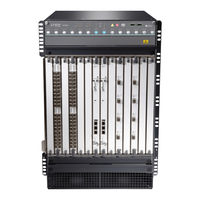
Juniper MX80 Datasheet (8 pages)
MX Series 3D UNIVERSAL EDGE ROUTERS
Brand:
Juniper
| Category:
Network Router
| Size: 0.74 MB
Table of Contents
Product Description
1
Features and Benefits
3
Specifications
6
Agency Approvals
6
Ordering Information
7
About Juniper Networks
8
Advertisement
Advertisement
Related Products
Juniper MX240
Juniper MX2020
Juniper MX5
Juniper MX10
Juniper MX10008
Juniper Networks MX150
Juniper MX2010
Juniper MX10003
Juniper Day One+ MX304
Juniper MX10004-BASE
Juniper Categories
Network Router
Switch
Gateway
Software
Network Hardware
More Juniper Manuals
Login
Sign In
OR
Sign in with Facebook
Sign in with Google
Upload manual
Upload from disk
Upload from URL