Sign In
Upload
Manuals
Brands
Inovance Manuals
Servo Drives
SV630P Series
Inovance SV630P Series Manuals
Manuals and User Guides for Inovance SV630P Series. We have
1
Inovance SV630P Series manual available for free PDF download: User Manual
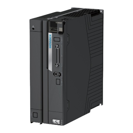
Inovance SV630P Series User Manual (710 pages)
Brand:
Inovance
| Category:
Servo Drives
| Size: 40.81 MB
Table of Contents
Preface
2
Table of Contents
5
General Safety Instructions
14
Selection Table
20
Selection
20
Models of MS1-R Series Motors and MS1-Z Series Motors
21
SV630P Series
25
Product Information
25
Description of the Model and Nameplate
25
Components
27
Servo Drives in Size a (Rated Power: 0.2 Kw to 0.4 Kw)
27
Servo Drives in Size B (Rated Power: 0.75 Kw)
28
Servo Drives in Size C and D (Rated Power: 1.0 Kw to 3.0 Kw)
30
Servo Drives in Size E (Rated Power: 5.0 Kw to 7.5 Kw)
32
Product Dimensions
34
Product Specifications
34
Electrical Specifications
34
Technical Specifications
37
Dynamic Brake Characteristics
39
Load Moment of Inertia
40
MS1-R Series Motor
41
Product Information
41
Description of the Model and Nameplate
41
Components
42
Motor Models
43
Product Specifications
43
Mechanical Characteristics
43
Overload Characteristics
45
Derating Characteristics
47
Temperature Curve of the Oil Seal
48
Selection Instructions
48
Low Inertia and Small Capacity (MS1H1)
49
Ms1H1-05B30Cb-T33*Z
49
Ms1H1-10B30Cb-T33*Z
50
Ms1H1-20B30Cb-T33*R
52
Ms1H1-40B30Cb-T33*R
53
Ms1H1-55B30Cb-T331R
54
Ms1H1-75B30Cb-T33*R
55
Ms1H1-10C30Cb-T33*R
56
Low Inertia and Medium Capacity (MS1H2)
57
Ms1H2-10C30Cb-T33*R
57
Ms1H2-10C30Cd-T33*R
58
Ms1H2-15C30Cb-T33*R
59
Ms1H2-15C30Cd-T33*R
60
Ms1H2-20C30Cb-T33*R
61
Ms1H2-20C30Cd-T33*R
62
Ms1H2-25C30Cb-T33*R
63
Ms1H2-25C30Cd-T33*R
64
Ms1H2-30C30Cb-T33*R
65
Ms1H2-30C30Cd-T33*R
66
Ms1H2-40C30Cb-T33*R
67
Ms1H2-40C30Cd-T33*R
68
Ms1H2-50C30Cb-T33*R
69
Ms1H2-50C30Cd-T33*R
70
Medium Inertia and Medium Capacity (MS1H3)
71
Ms1H3-85B15Cb-T33*R
71
Ms1H3-85B15Cd-T33*R
72
Ms1H3-13C15Cb-T33*R
73
Ms1H3-13C15Cd-T33*R
74
Ms1H3-18C15Cb-T33*R
75
Ms1H3-18C15Cd-T33*R
76
Ms1H3-29C15Cb-T33*R
77
Ms1H3-29C15Cd-T33*R
78
Ms1H3-44C15Cb-T33*R
79
Ms1H3-44C15Cd-T33*R
80
Ms1H3-55C15Cd-T33*R
81
Ms1H3-75C15Cd-T33*R
82
Medium Inertia and Small Capacity (MS1H4)
83
Ms1H4-10B30Cb-T33*Z
83
Ms1H4-20B30Cb-T33*R
84
Ms1H4-40B30Cb-T33*R
85
Ms1H4-55B30Cb-T331R
86
Ms1H4-75B30Cb-T33*R
87
Ms1H4-10C30Cb-T33*R
88
Options
89
List of Options
89
Cables
89
Cable Type
89
Model Description
90
Cable Selection
92
Electrical Peripherals
96
Fuse
96
Electromagnetic Contactor
96
Breaker
97
AC Input Reactor
97
EMC Filter
99
Magnetic Ring and Magnetic Buckle
101
Absolute Encoder Batteries
103
Installation
105
Installation of the Servo Drive
105
Unpacking Inspection
105
Installation Environment
106
Installation Clearance
107
Installation Dimensions
109
Installation Precautions
111
Installation Instructions
112
Installation of Optional Parts
113
Instructions for Installing the Fuse and Circuit Breaker
113
Instructions for Installing the AC Input Reactor
114
Instructions for Installing the EMC Filter
114
Installation of the Magnetic Ring and Ferrite Clamp
114
System Wiring Diagram
116
System Wiring
116
System Composition
118
电气接线图
120
Wiring Diagram of the Position Control Mode
120
Wiring Diagram for Torque Control Mode
121
Wiring Terminals
122
Wiring Precautions
122
Main Circuit Terminals
127
Wiring Precautions
127
Main Circuit Wiring Requirements
128
Recommended Cable Specifications and Models
129
Main Circuit Terminal Layout
134
Connecting the Motor (UVW)
138
Wiring of External EMC Filter
141
Wiring of the Power Supply
141
Grounding and Wiring
144
Description of Control Terminal (CN1)
147
Terminal Layout
148
Position Reference Input Signals
150
DI/DO Signals
157
Encoder Frequency-Division Output Signals
160
Wiring of the Brake
162
Encoder Terminal CN2
163
Terminal Layout
163
Connecting the Absolute Encoder
164
Installing Absolute Encoder Battery Box
166
Encoder Cable Specifications
168
Communication Terminals CN3 and CN4
169
Wiring and Setting of the Regenerative Resistor
173
Commissioning Tool
174
Operating Panel
174
Display Panel Components
174
Panel Display
174
Parameter Settings
178
Commissioning Software
184
Overview
184
To Install the Fan, Do as Follows
184
Connection
188
Introduction to the Software Tool
190
Commissioning and Operation
193
Commissioning Flowchart
193
Inspection before Commissioning
193
Power-On
194
Jog
195
Setting Parameters
197
Trial Run
209
Servo off
217
Adjustment
221
Overview
221
Inertia Identification
223
Offline Inertia Identification
224
Online Inertia Auto-Tuning
226
Auto Gain Tuning
228
Etune
228
Stune
233
Manual Gain Tuning
237
Basic Parameters
237
Gain Switchover
241
Comparison of Filters
245
Feedforward Gain
245
PDFF Control
247
Torque Disturbance Observer
248
Speed Observer
251
Model Tracking
253
Friction Compensation
255
Parameter Adjustment in Different Control Modes
256
Parameter Adjustment in the Position Control Mode
256
Parameter Adjustment in the Speed Control Mode
258
Parameter Adjustment in the Torque Control Mode
258
Vibration Suppression
258
Mechanical Resonance Suppression
259
Low-Frequency Resonance Suppression at the Mechanical End
263
Mechanical Characteristic Analysis
265
Function Overview
268
Basic Functions of the Servo Drive
270
Position Control Mode
270
Block Diagram of Position Control Parameters
271
Position Reference Input Setting
271
Reference Frequency Division/Multiplication (Electronic Gear Ratio)
289
Position Reference Filter
294
Position Deviation Clear
295
Frequency-Division Output
296
Motion Control/Internal Command/Positioning Completed/Proximity Functions
299
Interrupt Positioning
303
Homing
306
Speed Control Mode
322
Block Diagram of Speed Control Parameters
323
Speed Reference Input Setting
323
Ramp Function Setting
332
Zero Clamp
333
Speed Reference Limit
334
Speed-Related DO
335
Torque Control Mode
339
Block Diagram of Torque Control Parameters
340
Torque Reference Input Setting
340
Torque Reference Filter
343
Torque Reference Limit
344
Speed Limit in Torque Control Mode
348
Torque Reach Output
351
Mixed Control Mode
352
Absolute System
354
Overview
354
Related Parameters
354
Precautions for Use of the Battery Box
359
Auxiliary Functions
360
Software Position Limit
360
Software Reset
361
Motor Protection
361
DI Filter Time Setting
363
Communication
365
Modbus通信
365
Overview
365
Hardware Configuration
365
Data Frame Structure
369
Communication Parameters
376
Description of Parameters
377
H00 Servo Motor Parameters
377
H01 Servo Drive Parameters
383
H02 Basic Control Parameters
393
H03 Terminal Input Parameters
403
H04 Terminal Output Parameters
412
H05 Position Control Parameters
416
H06 Speed Control Parameters
437
H07 Torque Control Parameters
447
H08 Gain Parameters
454
H09 Gain Auto-Tuning Parameters
468
H0A Fault and Protection
478
H0B Display Parameters
489
H0C Communication Parameters
501
H0D Auxiliary Parameters
507
H11 Multi-Position Function Parameters
511
H12 Multi-Speed Operation References
530
H17 VDO/VDI Settings
544
H1B Motor Storage Property
561
H30 Servo Status Variables Read through Communication
563
H31 Related Variables Set through Communication
565
Parameter List
567
Parameter Group H00
567
Parameter Group H01
568
Parameter Group H02
573
Parameter Group H03
576
Parameter Group H04
579
Parameter Group H05
580
Parameter Group H06
585
Parameter Group H07
586
Parameter Group H08
588
Parameter Group H09
592
Parameter Group H0A
595
Parameter Group H0B
598
Parameter Group H0C
603
Parameter Group H0D
604
Parameter Group H11
605
Parameter Group H12
609
Parameter Group H17
613
Parameter Group H1B
617
Parameter Group H30
618
Parameter Group H31
618
Troubleshooting
619
Fault Levels and Display
619
Troubleshooting During Startup
620
Reset Method after Troubleshooting
627
Description of Warning Codes
628
Description of Fault Codes
639
Solutions to Faults
639
Internal Faults
673
List of Alarm Codes
674
List of Fault Codes
675
Maintenance
678
Routine Maintenance
678
Routine Checklist
678
Routine Cleaning List
678
Periodic Maintenance
679
Periodic Checklist
679
Periodic Maintenance List
679
Parts Replacement
680
Replacing the Motor Flat Key
680
Removing the Motor Oil Seal
680
Appendix
682
Compliance Requirements
682
CE Certifications
682
Requirement for Compliance with EMC Directive
682
Requirements for Compliance with LVD
683
Solutions to Common EMC Problems
684
Malfunction of the Residual Current Device (RCD)
684
Harmonic Suppression
686
Control Circuit Interference
686
High-Speed Pulse Interference
686
Common I/O Signal Interference
686
RS485&CAN Communication Interference
687
Capacity Selection Example for Servo Motor
688
Capacity Selection Example for Position Control
688
Capacity Selection Example for Speed Control
691
Canlink Enhanced Axis Control Parameters
694
DIDO Function Assignment
695
Display of Monitoring Parameters
701
Ordering
707
服务与支持
708
Advertisement
Advertisement
Related Products
Inovance SV660NS2R8I-FS
Inovance SV660NS012I-FS
Inovance SV660F Series
Inovance SV660FS5R5I
Inovance SV660FS7R6I-FS
Inovance SV660FT5R4I-FS
Inovance SV680NS1R6I
Inovance SV680NS7R6I
Inovance SV680NS027I
Inovance SV680NT017I
Inovance Categories
Servo Drives
DC Drives
Controller
Control Unit
Inverter
More Inovance Manuals
Login
Sign In
OR
Sign in with Facebook
Sign in with Google
Upload manual
Upload from disk
Upload from URL