Sign In
Upload
Manuals
Brands
Harris Manuals
Receiver
Intraplex HD Link RF
Harris Intraplex HD Link RF Manuals
Manuals and User Guides for Harris Intraplex HD Link RF. We have
1
Harris Intraplex HD Link RF manual available for free PDF download: Installation & Operation Manual
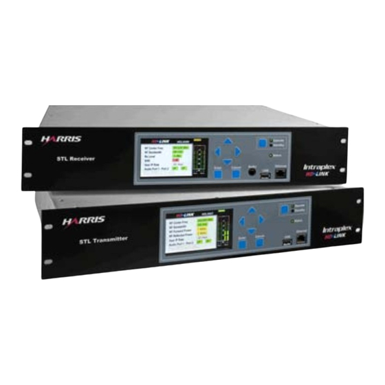
Harris Intraplex HD Link RF Installation & Operation Manual (181 pages)
Studio-to-Transmitter Link
Brand:
Harris
| Category:
Receiver
| Size: 5.71 MB
Table of Contents
Table of Contents
7
Section 1 - Introduction
15
Key Features
15
Manual Use
15
Manual Scope
15
System Components
16
Transmitter and Receiver
16
Front Panel Interface
16
Web Browser Interface
16
Section 2 - Functional Design
17
General System Description
17
High Definition (HD) STL Development
17
Modulation
17
HD Radio Signal on an STL
18
Data Bandwidth Requirements
18
STL Carrying Capacity
18
Data Quality
19
Figure 2-1. HD Link STL IP Gateway Architecture
20
Network Topology Support
21
Figure 2-2. Network Topology with Return Path
21
HD Link Features
22
Audio Transport
22
Data Transport
22
RF Performance
22
Setup & Operation
23
Connectors & Display
23
Audio Transport Using G.722 Encoding
23
In-Band Messaging and Synchronization
24
Redundancy
24
Section 3 - Installation
27
Installation Preparation
27
Tools & Cables Required
27
Equipment Unpacking and Inspection
27
Transmitter & Receiver Installation
27
Wiring & External Connections
28
Available Connections
28
Figure 3-1. HD Link Front Panel with Connectors - Receiver
28
Figure 3-2. HD Link Transmitter and Receiver - Rear View
28
Table 3-1. HD Link Connections
29
Figure 3-3. Contact Input Circuitry
30
Required Connections
31
Redundancy Installation & Wiring
31
Redundant Transmitters
32
Redundant Receivers
32
Unit Powering
33
Power Supplies
33
Radio Frequency Power Status
33
Figure 3-4. Initial Front Panel Display Screen
33
Figure 3-5. Transmitter RF Link Detail Screen
34
Section 4 - Front Panel Display Configuration & Operation
35
Front Panel Buttons & Screens
35
Panel Buttons & Screen Navigation
35
Initial Screen
36
Figure 4-1. HD Link Front Panel - Receiver
36
Main Screen & Screen Components
37
Figure 4-2. Initial Screen - Transmitter and Receiver
37
Figure 4-3. Main Front Panel Screen
38
Status Screens
40
Figure 4-4. Main Status - Transmitter
40
Figure 4-5. Main Status - Receiver
40
Figure 4-6. Status Levels Flow Chart
42
Figure 4-7. Status Audio Port 1 - Transmitter
43
Figure 4-8. Status Audio Port 1 - Receiver
43
Figure 4-9. Status Audio Port 2 - Transmitter
44
Figure 4-10. Status Audio Port 2 - Receiver
44
Figure 4-11. Status RF Link Detail - Transmitter
45
Figure 4-12. Status RF Link Detail - Receiver
46
Figure 4-13. Status System Alarm State Detail
46
Figure 4-14. System Alarm State Detail Alarm Info Detail
47
Figure 4-15. Status User IP Stats Menu
47
Figure 4-16. User IP Stats Forward Path Pkt Stats - Transmitter
48
Figure 4-17. User IP Stats Forward Path Pkt Stats - Receiver
48
Figure 4-18. User IP Stats Return Path Pkt Stats - Transmitter
49
Figure 4-19. User IP Stats Return Path Pkt Stats - Receiver
49
Figure 4-20. Status Modem Stats
50
System Setup Screens
51
Figure 4-22. Status 2 System Contacts State Detail
51
Figure 4-23. System Contacts State Detail Contacts Alarm Info Detail
51
Figure 4-24. Main System Setup
51
Figure 4-25. System Setup Levels Flow Chart
52
Figure 4-26. System Setup Network Setup Menu
53
Figure 4-27. Network Setup HD Port
54
Figure 4-28. HD Port IP Address
54
Figure 4-29. HD Port IP Netmask
55
Figure 4-30. HD Port Admin State
56
Figure 4-31. HD Port Auto Negotiation
56
Figure 4-32. HD Port Speed
57
Figure 4-33. Network Setup LAN Port
57
Figure 4-34. LAN Port IP Address
58
Figure 4-35. LAN Port IP Netmask
59
Figure 4-36. LAN Port Return Path
59
Figure 4-37. LAN Port Return Path Peer IP Address
60
Figure 4-38. LAN Port Admin State
60
Figure 4-39. LAN Port Auto Negotiation
61
Figure 4-40. LAN Port Speed
61
Figure 4-41. Network Setup Default Gateway
62
Figure 4-42. Default Gateway Default Gateway IP Address
63
Figure 4-43. Default Gateway with New Gateway Not Applied
63
Figure 4-45. Default Gateway with Removed Gateway Change Not Applied
64
Figure 4-48. Display Brightness
65
Figure 4-50. Inactivity Timer Change Inactivity Wait Time
66
Figure 4-52. System Setup Redundancy Setup – Transmitter
67
Figure 4-54. Redundancy Setup Redundancy Role Change
68
Service Setup Screens
69
Figure 4-57. Service Setup Levels Flow Chart
70
Figure 4-59. RF Profile Center Frequency
71
Figure 4-60. RF Profile Bandwidth
72
Figure 4-62. RF Profile Output Power
73
Figure 4-64. Service Setup Service Profile – Transmitter and Receiver
74
Figure 4-66. Service Profile: Audio 2 Port Mode
75
Figure 4-67. Service Setup Service Sync
76
Test Screens
77
Figure 4-69. Main Test Menu – Transmitter and Receiver
78
Firmware and File Management Screens
79
Figure 4-74. Firmware and File Management Levels Flow Chart
80
Figure 4-75. Firmware and File Management Firmware Management
81
Figure 4-77. Firmware Upgrade Example Select File
82
Figure 4-80. Firmware Management Export System Files
83
Figure 4-82. Export System Files Export Error
84
Figure 4-85. Firmware Management Package Version Information
85
Figure 4-87. Firmware and File Management File Management
86
Figure 4-90. Select File Confirm File Selection
87
Figure 4-93. Firmware and File Management Configuration File Management
88
Figure 4-96. Save Configuration Save Configuration File Failed
89
Figure 4-98. Configuration File Management Restore Default Configuration
90
Configuration Process
91
Configure the HD Port
91
Figure 4-104. Main Screen System Setup
92
Configure the LAN Port
93
Configure the RF Profile Parameters
93
Configure the Service Profile Parameters
94
Configure the Receiver's Service Sync
94
Configure the System for Redundancy
95
Figure 4-113. System Setup Network Setup – Transmitter
96
Figure 4-116. Redundancy Setup – Receiver
97
Figure 4-117. HD Port – Receiver
98
Set or Unlock the Display
99
Figure 4-122. Main System Setup
100
Figure 4-125. Display Inactivity Timer
101
Operation Guidelines
102
Upgrade Procedure
102
Figure 4-128. Example Select File
103
Section 5 - Web Browser Interface Configuration & Operation
105
Browser Compatibility
105
Interface Access
105
Interface
106
Screen Banner
106
Navigation Bar
106
Alarms
107
Figure 5-3. Alarms | Current Alarms Page
108
Figure 5-4. Alarms | Alarm History Page
109
Figure 5-5. Alarm | Alarm Definitions Page
110
Figure 5-6. Alarm Definition Edit Dialog Box
111
Figure 5-7. Alarms | Alarm Logging Page
112
Program Services
113
Figure 5-8. Program Services Page – Transmitter and Receiver
114
Radio Link
119
Figure 5-12. Radio Link Page – Transmitter and Receiver
120
General Configurations
122
Advanced Settings
123
Figure 5-14. General | Advanced Settings Page – Transmitter and Receiver
124
Figure 5-15. General | Configuration/Firmware Management Page
126
Figure 5-16. General | Contacts Page
127
Figure 5-17. Contacts: Map Digital Output Contact Dialog Box
128
Network Configurations
129
Figure 5-19. Network | Ethernet Interfaces Page
130
Figure 5-20. Network | Forwarding Table
131
Figure 5-21. Forwarding Table: Add a Route Dialog Box
132
Figure 5-22. Network | SNMP Configuration Page
133
Figure 5-23. Network | TCP Connections Page
134
Figure 5-24. Network | UDP Listeners Page
135
Figure 5-25. Network | Arp/Proxy ARP Page
136
Security Configurations
137
Figure 5-27. Security | Access Lists
138
Figure 5-29. STL Access: Add a Destination Dialog Box
139
Figure 5-30. Security | Accounts Page
140
Figure 5-31. Accounts Page: Add User Account Dialog Box
141
Performance
142
Figure 5-33. Performance | Audio Channels Page – Transmitter and Receiver
143
Figure 5-34. Performance | Packet Statistics Page – Transmitter and Receiver
144
Figure 5-35. Performance | SNMP Statistics Page
146
Figure 5-36. Performance | TCP/UDP Statistics Page
147
Figure 5-37. Performance | IP Statistics Page
149
Figure 5-38. Performance | ICMP Statistics Page
150
Configuration Process
151
Configure HD Port & LAN Port
151
Configure Radio Link Parameters
151
Figure 5-39. Radio Link Page – Transmitter
152
Configure Program Services Parameters
153
Configure the System for Redundancy
154
Operation Guidelines
159
Upgrade Procedure
159
Figure 5-48. Upgrade Firmware Dialog Box
160
Section 6 - Testing & Troubleshooting
161
Testing
161
Test Tone
161
Audio Port Monitor
161
Redundancy Testing
162
Figure 6-6. Transmitter Web Browser Interface with Status on Banner
163
Figure 6-6. Contacts Page for Active Transmitter
164
Figure 6-8. Receiver Web Browser Interface with Status on Banner
165
Troubleshooting
166
Guidelines
166
Redundancy Guidelines
167
Possible Error Messages
168
Section 7 - Specifications
171
Detailed Specifications
171
Radio Frequency (RF)
171
Audio Performance
171
System
173
Networking
173
Control & Monitoring
173
Mechanical & Environmental
174
Notice of FCC Compliance
174
Compliance with FCC Part 15 Requirements
174
Compliance with FCC Part 74 Requirements
174
Section 8 - Glossary
175
Appendix A - Services & Minimum Rx Signal Level
179
Advertisement
Advertisement
Related Products
Harris Intraplex IntraLink-IP
Harris Intelligent Transmitter Platinum-i Series
Harris IconMaster
Harris CS7000
Harris MS-15
Harris PR-150C
Harris PR-D350
Harris PT-150C
Harris PT-D350
Harris RF-590
Harris Categories
Transmitter
Amplifier
Radio
Receiver
Test Equipment
More Harris Manuals
Login
Sign In
OR
Sign in with Facebook
Sign in with Google
Upload manual
Upload from disk
Upload from URL