Table of Contents
Troubleshooting

Related Manuals for Harris Intraplex HD Link RF


Summary of Contents for Harris Intraplex HD Link RF
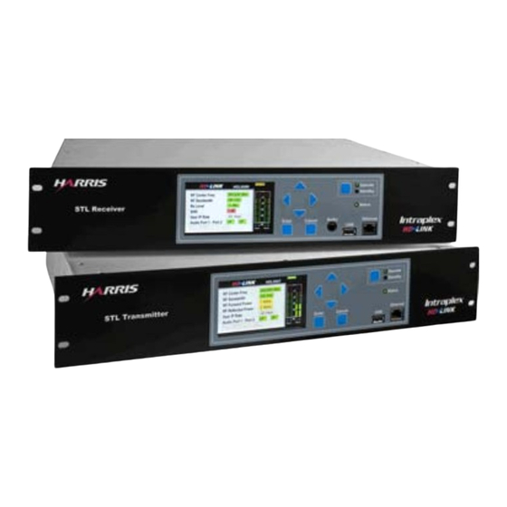
- Page 1 No header ® Intraplex HD Link™ RF Studio-to-Transmitter Link Installation & Operation Manual HD Link Studio-to-Transmitter Link Version 2 TOTAL CONTENT DELIVERY SOLUTIONS | Managing content. Delivering results. No footer...
- Page 2 If you have a technical question or issue with your Intraplex document is subject to change without Products equipment, please check our customer support web notice. Harris makes no warranty of any page: kind with regard to this material, http://www.broadcast.harris.com/support/productsupport.asp...
- Page 3 Added Redundancy subsection to Testing and 6.1.3, 6.2.2 6-2 – 6-6, Troubleshooting sections. Updated Audio Frequency Response and added 7.1.2 Audio Input Level and Audio Output level to Specifications section. Harris Corporation Intraplex Products...
- Page 4 No header This page is left blank intentionally. Harris Corporation Intraplex Products...
- Page 5 Congratulations on purchasing the Intraplex HD Link radio frequency (RF) studio-to-transmitter link (STL)! This document provides initial system setup instructions. The installation and operation manual gives more detail on system operation. To download the most current version of the manual, go to http://www.broadcast.harris.com/support/. A) Install Transmitter & Receiver Install each unit into a 19"...
- Page 6 Intraplex HD Link RF STL Quick Start Guide Version 2, April 2010 Configure LAN Port parameters in a similar way to the HD Port parameters in Section D, Step 3. F) Configure RF Profile Parameters On the HD Link Main page, select Service Setup and press Enter to access the screen (Figure 5).
-
Page 7: Table Of Contents
3.3 Wiring & External Connections ............3-2 3.3.1 Available Connections ................3-2 3.3.2 Required Connections ................3-5 3.4 Redundancy Installation & Wiring ............3-5 3.4.1 Redundant Transmitters .................3-6 3.4.2 Redundant Receivers ................3-6 3.5 Unit Powering ................... 3-7 3.4.1 Power Supplies ..................3-7 Harris Corporation Intraplex Products... - Page 8 5.4.3 Configure Program Services Parameters ..........5-49 5.4.4 Configure the System for Redundancy ............ 5-50 5.5 Operation Guidelines ..............5-55 5.6 Upgrade Procedure ................. 5-55 Section 6 – Testing & Troubleshooting ......... 6-1 6.1 Testing ................... 6-1 Harris Corporation Intraplex Products...
- Page 9 7.2 Notice of FCC Compliance ..............7-4 7.2.1 Compliance with FCC Part 15 Requirements ..........7-4 7.2.2 Compliance with FCC Part 74 Requirements ..........7-4 Section 8 – Glossary ..............8-1 Appendix A – Services & Minimum Rx Signal Level ......A-1 Harris Corporation Intraplex Products...
- Page 10 Figure 4-40. LAN Port Speed ................4-27 Figure 4-41. Network Setup Default Gateway ............4-28 Figure 4-42. Default Gateway Default Gateway IP Address ........4-29 Figure 4-43. Default Gateway with New Gateway Not Applied ........4-29 Harris Corporation Intraplex Products...
- Page 11 Figure 4-93. Firmware and File Management Configuration File Management .... 4-54 Figure 4-94. Configuration File Management Save Configuration File ......4-54 Figure 4-95. Save Configuration File Save Configuration File Successful ....4-54 Figure 4-96. Save Configuration Save Configuration File Failed........ 4-55 Harris Corporation Intraplex Products...
- Page 12 Figure 5-18. Contacts: Map Input Contact Dialog Box ..........5-25 Figure 5-19. Network | Ethernet Interfaces Page ............5-26 Figure 5-20. Network | Forwarding Table ..............5-27 Figure 5-21. Forwarding Table: Add a Route Dialog Box ..........5-28 Harris Corporation Intraplex Products...
- Page 13 Table 3-5. Serial Async #1 and #2 Pin Connections .............3-5 Table 3-6. Analog, AES, and AUX Audio Pin Connections ..........3-5 Table 3-7. Transmitter RJ-25 MAIN/ALT Pin Connections ..........3-6 Table 4-1. Front Panel Buttons ..................4-2 Table A-1. Receive Signal Sensitivity and Bandwidths per Application ......A-1 Harris Corporation Intraplex Products...
- Page 14 No header here This page is left blank intentionally. viii Harris Corporation Intraplex Products...
-
Page 15: Section 1 - Introduction
This manual is the primary reference document for installing, configuring, operating, and troubleshooting the HD Link digital STL. If you have additional questions pertaining to the operation of your Intraplex system, you can contact Harris Customer Service: ● U.S., Canada, and Latin America: +1-217-222-8200 or tsupport@harris.com... -
Page 16: System Components
HD port and LAN port parameters on both the transmitter and receiver (Sections 4.1.5 and 4.2). The Web browser interface is similar to the front panel display, showing all the status that the digital display does. Harris Corporation Intraplex Products... -
Page 17: Section 2 - Functional Design
Carefully designing and optimizing the RF receiver can reduce the overhead used for pilot symbols. When a digital 950 MHz STL carries Ethernet data to broadcast HD Radio, some problems arise. The next subsections discuss possible problems and how the HD Link system addresses and corrects them. Harris Corporation Intraplex Products... -
Page 18: Hd Radio Signal On An Stl
QAM orders is around 3 to 4 dB per step. For example, 128-QAM requires 3 to 4 dB more signal to achieve the same BER performance as 64-QAM. Harris Corporation Intraplex Products... -
Page 19: Data Quality
The system’s support of standard network management protocol functions (such as HTTP, SNMP, FTP, Telnet, and ICP), allowing for more effective troubleshooting and management. Harris Corporation Intraplex Products... -
Page 20: Figure 2-1. Hd Link Stl Ip Gateway Architecture
Without this smoothing function, the transmission of instantaneous bursts in the HD IP stream requires far greater air bandwidth. Finally, a scheduling function should ensure that the strict priority is followed when queuing packets for transport across the HD Link system. Harris Corporation Intraplex Products... -
Page 21: Network Topology Support
The tunnel ends at the studio site IP gateway, which de-encapsulates the tunneled packets and routes them appropriately to the HD node on the studio network (Figure 2-2). The tunnel encapsulation ensures the packets are routable and traversable across the Network Address Translator (NAT) devices in the service provider’s network. Harris Corporation Intraplex Products... -
Page 22: Hd Link Features
An RS-232 asynchronous data channel, up to 9600 bps, on each main program audio channel. 2.3.3 RF Performance The HD Link system gives powerful, reliable RF performance with ● 1, 2, or 5 Watts RF power. Harris Corporation Intraplex Products... -
Page 23: Setup & Operation
● 14 bit sample size ● 16 ksps sample rate ● 64 kbps data rate per channel ● 50 to 7000 Hz, ±1 dB audio frequency response ● Dynamic range greater than 65 dB Harris Corporation Intraplex Products... -
Page 24: In-Band Messaging And Synchronization
Standalone and connected as shown. Other Network Elements Status (e.g. Exporter) HDLINK Control HD Port RF OUT- A RF OUT- Ant Main/Alt Ethernet Controller Switch RF OUT- B HD Port HDLINK Control Status Figure 2-3. Transmitter Redundancy Harris Corporation Intraplex Products... - Page 25 HD Link systems. Section 5.3.6.2 – Advanced Settings and Section 5.4.4 – Configure the System for Redundancy give details on using the Web browser interface to configure primary and redundant HD Link systems. Harris Corporation Intraplex Products...
- Page 26 No header here This page is left blank intentionally. 2-10 Harris Corporation Intraplex Products...
-
Page 27: Section 3 - Installation
(Bill of Materials): • Chassis with rack mount in good condition • Power supply, cables, and utilities If you have questions regarding possible equipment damage or shipping errors, contact Harris Customer Service: ● U.S., Canada, and Latin America: +1-217-222-8200 or tsupport@harris.com... -
Page 28: Wiring & External Connections
The units (Figure 3-2) have similar rear connections, which Table 3-1 identifies. Each unit also has a variable speed fan to prevent overheating and minimize noise, assuring a high-quality audio sound. Figure 3-2. HD Link Transmitter and Receiver – Rear View Harris Corporation Intraplex Products... -
Page 29: Table 3-1. Hd Link Connections
AES sync shield Unused Digital output (+) Unused AES sync (-) Unused Digital output shield/drain Digital output (-) The HD Link receiver has AES external clock functionality; these pin connections are not functional on the transmitter. Harris Corporation Intraplex Products... -
Page 30: Figure 3-3. Contact Input Circuitry
There are both normally closed and normally open alarm relay outputs. The alarm relays map to events such as loss of signal. You can configure them to map to various system parameters. Section 5.3.3.3 – Alarm Definitions gives alarm configuration details. Harris Corporation Intraplex Products... -
Page 31: Required Connections
On the HD Link transmitter at the studio site, an external Main/Alt controller links the two transmitters. On the HD Link receiver at the transmit site, the two receivers can connect directly or with the external Main/Alt controller. Harris Corporation Intraplex Products... -
Page 32: Redundant Transmitters
2. Plug the other end of the DB-26 cable into the Broadcast tools audio switcher. 3. Plug one end of the provided crossover wire cable into the MAIN/ALT connector on Receiver A. 4. Plug the other end of the crossover wire cable into the MAIN/ALT connector on Receiver B. Harris Corporation Intraplex Products... -
Page 33: Unit Powering
Red = An alarm due to a serious hardware/software operational error ● White = Currently applied value The bar graph display on the right shows the current audio levels (in decibels) being transported on Ports 1 and 2 with these color codes: Harris Corporation Intraplex Products... -
Page 34: Figure 3-5. Transmitter Rf Link Detail Screen
The transmitter’s RF Link Status screen (Figure 3-5) also shows ● Output power setting. ● Forward power. ● Reflected power. Figure 3-5. Transmitter RF Link Detail Screen Check your antenna cables and connections and these screens to confirm power delivery to your transmitting antenna. Harris Corporation Intraplex Products... -
Page 35: Section 4 - Front Panel Display Configuration & Operation
Some screens vary between the two units, particularly when displaying RF parameters. This section shows both transmitter and receiver screens whenever they vary. 4.1.1 Panel Buttons & Screen Navigation The front panel has seven blue buttons (Figure 4-1) you can use to Harris Corporation Intraplex Products... -
Page 36: Initial Screen
Get more detail or open an item to edit it. Cancel Drill up a level. Return to the previous screen without saving changes. 4.1.2 Initial Screen When you turn on the HD Link system, this initial screen appears (Figure 4-2): Harris Corporation Intraplex Products... -
Page 37: Main Screen & Screen Components
Press Enter to access the Main screen (Figure 4-3) and begin to navigate between display screens. 4.1.3 Main Screen & Screen Components Press Enter on the default screen to access the Main screen (Figure 4-3), which is similar to a Web site’s home page. Harris Corporation Intraplex Products... -
Page 38: Figure 4-3. Main Front Panel Screen
Ethernet link up, as one port is mirroring the other one. The M is red if the mirror port is not connected to anything or the other device is not up. Harris Corporation Intraplex Products... - Page 39 Firmware and File Management: Select this menu and press Enter to ● Upgrade or rollback the system firmware. ● Copy or restore configurations. ● Export log or system files. ● View firmware and package version information. ● Restart the system. Harris Corporation Intraplex Products...
-
Page 40: Status Screens
Enter on the transmitter to view these fields: ● Output power (both configured and measured) ● Reflected output power (measured) ● VSWR (Voltage Standing Wave Ratio) ● Modulation Select the RF Link command and press Enter on the receiver to view these fields: Harris Corporation Intraplex Products... - Page 41 More: Select this command and press Enter to go to the next Status screen. Color Codes: Green UP = no alert; yellow DOWN = alert condition. Figure 4-6 shows a flow chart of screens to which you can drill down from the Status menu option. Harris Corporation Intraplex Products...
-
Page 42: Figure 4-6. Status Levels Flow Chart
(Figures 4-7 and 4-8), and Audio Port 2 is compressed (Figures 4-9 and 4-10). Select Audio Port 1 on the first Status screen and press Enter to access the Audio Port 1 screen (Figures 4-7 and 4-8). Harris Corporation Intraplex Products... -
Page 43: Figure 4-7. Status Audio Port 1 - Transmitter
● Config or Cfg [Configuration] ● [Sample] Rate ● BiPhase ● ● Mute [Muted output due to errors] ● Frame or FrmLoss [Frame Loss] ● Word [length error] ● Audio ● NonAudio ● Audio [AES/EBU error] Harris Corporation Intraplex Products... -
Page 44: Figure 4-9. Status Audio Port 2 - Transmitter
Test tone (Tone ON or Tone OFF). Audio Setup: ● Current audio setup (Stereo, Mono, or Off). ● Sample rate in KHz. ● Word length in bits. ● Signal gain in dBu. ● Auxiliary data rate (HRS or APT). 4-10 Harris Corporation Intraplex Products... -
Page 45: Figure 4-11. Status Rf Link Detail - Transmitter
VSWR: Current Voltage Standing Wave Ratio. Modulation: Current modulation the system is using. Back: Select this command and press Enter to return to the previous screen. Color Codes: Green = power up; red = power down; white = configured parameter. Harris Corporation 4-11 Intraplex Products... -
Page 46: Figure 4-12. Status Rf Link Detail - Receiver
More: Select this command and press Enter to view any additional alarms. This command does not appear if there are no additional alarms. Color Codes: Red = major alarm; yellow = minor alarm. Cancel: Press this button to return to the previous screen. 4-12 Harris Corporation Intraplex Products... -
Page 47: Figure 4-14. System Alarm State Detail Alarm Info Detail
Back: Select this command and press Enter to return to the previous screen. Forward Path Pkt Stats Select Forward Stats on the User IP Stats menu screen to access the Forward Path Pkt Stats screen (Figures 4-16 and 4-17). Harris Corporation 4-13 Intraplex Products... -
Page 48: Figure 4-16. User Ip Stats Forward Path Pkt Stats - Transmitter
Back: Select this command and press Enter to return to the previous screen. Return Path Pkt Stats Select Return Stats on the User IP Stats menu screen to access the Return Path Pkt Stats screen (Figures 4-18 and 4-19). 4-14 Harris Corporation Intraplex Products... -
Page 49: Figure 4-18. User Ip Stats Return Path Pkt Stats - Transmitter
Back: Select this command and press Enter to return to the previous screen. 4.1.4.6 Modem Stats Detail (Receiver Only) Select Modem Stats on the Status screen to access the Modem Stats menu screen (Figure 4-20). Harris Corporation 4-15 Intraplex Products... -
Page 50: Figure 4-20. Status Modem Stats
Color Codes: Green = system Active or No alarm; red = Major alarm; yellow = system on standby or Minor alarm. 4.1.4.8 System Contacts State Detail Select Sys Contacts State on the Status 2 screen to access the System Contacts State detail screen (Figure 4-22). 4-16 Harris Corporation Intraplex Products... -
Page 51: System Setup Screens
Back: Select this command and press Enter to return to the previous screen. 4.1.5 System Setup Screens Select System Setup on the Main front panel screen to access the System Setup menu screen (Figure 4-24). Figure 4-24. Main System Setup Harris Corporation 4-17 Intraplex Products... -
Page 52: Figure 4-25. System Setup Levels Flow Chart
Pkts rcvd with CRC errors Clear Modem Stats Redundancy Setup Primary Redundancy Role Secondary Standalone Audio Mute Pass Audio on Standby Control - Rx Mute Audio on Standby Figure 4-25. System Setup Levels Flow Chart 4-18 Harris Corporation Intraplex Products... -
Page 53: Figure 4-26. System Setup Network Setup Menu
Default Gateway: Select this command and press Enter to access the Default Gateway screen to add or change the gateway IP address. Back: Select this command and press Enter to return to the previous screen. Harris Corporation 4-19 Intraplex Products... -
Page 54: Figure 4-27. Network Setup Hd Port
Select IP Address on the HD Port screen to access the IP Address screen (Figure 4-28). Figure 4-28. HD Port IP Address This screen shows the IP address assigned to the HD port. Press these buttons on the display to change this address: 4-20 Harris Corporation Intraplex Products... -
Page 55: Figure 4-29. Hd Port Ip Netmask
Note: If you make any changes to this screen, you must select Apply and press Enter on the previous screen to save and apply changes. HD Port Admin State Select Admin State on the HD Port menu screen to access the Admin State screen (Figure 4- 30). Harris Corporation 4-21 Intraplex Products... -
Page 56: Figure 4-30. Hd Port Admin State
Cancel: Press this button to return to the previous screen. Note: If you make any changes to this screen, you must select Apply and press Enter on the previous screen to save and apply changes. 4-22 Harris Corporation Intraplex Products... -
Page 57: Figure 4-32. Hd Port Speed
LAN Port Detail Select LAN Port on the Network Setup menu screen to access the LAN Port screen (Figure 4-33). Figure 4-33. Network Setup LAN Port – Transmitter and Receiver Harris Corporation 4-23 Intraplex Products... -
Page 58: Figure 4-34. Lan Port Ip Address
Cancel: Press this button to return to the previous screen. Note: If you make any changes to this screen, you must select Apply and press Enter on the previous screen to save and apply changes. 4-24 Harris Corporation Intraplex Products... -
Page 59: Figure 4-35. Lan Port Ip Netmask
Press Cancel to erase your changes and return to the previous address. Color Codes: White = currently applied value; yellow = value changed but not saved or applied. Cancel: Press this button to return to the previous screen. Harris Corporation 4-25 Intraplex Products... -
Page 60: Figure 4-37. Lan Port Return Path Peer Ip Address
Press the vertical buttons to change the state to UP () or DOWN (). • Press Enter to keep changes until you can Apply them on the previous screen. • Press Cancel to erase your changes and return to the previous setting. 4-26 Harris Corporation Intraplex Products... -
Page 61: Figure 4-39. Lan Port Auto Negotiation
Note: If AutoNeg is ON, you cannot change the speed. To adjust the speed, first set AutoNeg to OFF (previous section). Select Speed on the LAN Port menu screen to access the Speed screen (Figure 4-40). Figure 4-40. LAN Port Speed Harris Corporation 4-27 Intraplex Products... -
Page 62: Figure 4-41. Network Setup Default Gateway
Note: After drilling down to set or change the gateway IP address, you must select Apply on this screen and press Enter for the changes to take effect. Add/Change Default Gateway IP Address Select Add/Change Default Gateway on the Default Gateway screen to access the Default Gateway IP Address screen (Figure 4-42). 4-28 Harris Corporation Intraplex Products... -
Page 63: Figure 4-42. Default Gateway Default Gateway Ip Address
Enter to save the new gateway (Figure 4-44). Figure 4-44. Successful Change Press Enter to return to the previous screen. The new IP address on Default Gateway screen now appears in white, indicating the change has been saved. Harris Corporation 4-29 Intraplex Products... -
Page 64: Figure 4-45. Default Gateway With Removed Gateway Change Not Applied
4-47) and configure various display screen characteristics. Figure 4-47. System Setup Display Brightness: Select this command and press Enter to access the Brightness configuration screen to increase or decrease the brightness of HD Link screens on the panel display. 4-30 Harris Corporation Intraplex Products... -
Page 65: Figure 4-48. Display Brightness
Inactivity Wait Time: Select the field next to this command and press Enter (Figure 4-50) to change the length of time before the system turns off the display: • 60 minutes • 30 minutes • 10 minutes • 5 minutes • 3 minutes • 1 minute • 30 seconds Harris Corporation 4-31 Intraplex Products... -
Page 66: Figure 4-50. Inactivity Timer Change Inactivity Wait Time
To unlock the display and regain access to the screens, perform these steps: 1. Press the left arrow button three times. 2. Press Cancel. 3. Press Enter. The padlock icon should now disappear, indicating the screen menu is once more accessible. 4-32 Harris Corporation Intraplex Products... -
Page 67: Figure 4-52. System Setup Redundancy Setup – Transmitter
Enter for the changes to take effect. Section 4.2.6 gives more information on configuring your transmitters and receivers for redundancy. Redundancy Role Select Redundancy Role on the Redundancy Setup front panel screen to access the Redundancy Role configuration screen (Figure 4-54). Harris Corporation 4-33 Intraplex Products... -
Page 68: Figure 4-54. Redundancy Setup Redundancy Role Change
Press Cancel to erase your changes and return to the previous value. You can set the Audio Mute Control to Pass Audio on Standby or Mute Audio on Standby. The default is for the receiver, when in Standby mode, to mute audio signals (to drop the 4-34 Harris Corporation Intraplex Products... -
Page 69: Service Setup Screens
Service Sync: Select this command and press Enter to access the Service Sync configuration screen. Back: Select this command and press Enter to return to the previous screen. Figure 4-57 shows a flow chart of screens to which you can drill down from the Service Setup menu option. Harris Corporation 4-35 Intraplex Products... -
Page 70: Figure 4-57. Service Setup Levels Flow Chart
Output Power (transmitter only): Access the Output Power configuration screen. Back: Select this command and press Enter to return to the previous screen. Apply: Select this command and press Enter to save and apply your changes. 4-36 Harris Corporation Intraplex Products... -
Page 71: Figure 4-59. Rf Profile Center Frequency
Note: If you make any changes to this screen, you must select Apply and press Enter on the previous screen to save and apply changes. Bandwidth Select Bandwidth on the RF Profile front panel screen to access the Bandwidth configuration screen (Figure 4-60). Harris Corporation 4-37 Intraplex Products... -
Page 72: Figure 4-60. Rf Profile Bandwidth
Cancel: Press this button to return to the previous screen. Note: If you make any changes to this screen, you must select Apply and press Enter on the previous screen to save and apply changes. 4-38 Harris Corporation Intraplex Products... -
Page 73: Figure 4-62. Rf Profile Output Power
Coding Rate: Current channel coding rate. You cannot make any changes to the parameter status on this screen. Back: Select this command and press Enter to return to the previous screen. Color Codes: White = currently applied value. Harris Corporation 4-39 Intraplex Products... -
Page 74: Figure 4-64. Service Setup Service Profile – Transmitter And Receiver
Left field – Press the up or down arrow () to change the Port Mode to one of these options: • Mono • Stereo • ● Middle field – Press the up or down arrow () to change the Sample Rate to one of these rates: 4-40 Harris Corporation Intraplex Products... -
Page 75: Figure 4-66. Service Profile: Audio 2 Port Mode
Aux 1: Press the up or down arrow () to navigate to the Aux 1 row (Figure 4-66) and then press the left or right arrow () to select a parameter field to change on the Aux 1 row: ● ON or OFF ● Data Rate - HRS or APT Harris Corporation 4-41 Intraplex Products... -
Page 76: Figure 4-67. Service Setup Service Sync
Audio channel parameters • On or off • Sampling rate • Word length • Stereo or mono mode ● Auxiliary audio channel state – On or off ● LAN port IP address for return path tunneling 4-42 Harris Corporation Intraplex Products... -
Page 77: Test Screens
Note: If you make any changes to this screen, you must select Apply and press Enter on the previous screen to save and apply changes. 4.1.7 Test Screens Select Test on the Main front panel screen to access the Test menu screen (Figure 4-69). Harris Corporation 4-43 Intraplex Products... -
Page 78: Figure 4-69. Main Test Menu – Transmitter And Receiver
Select one of these ports and press Enter to toggle between ON and OFF for the test tone on the selected port: ● Audio Port 1 ● Audio Port 2 ● Aux Port 1 ● Aux Port 2 4-44 Harris Corporation Intraplex Products... -
Page 79: Firmware And File Management Screens
Export files from an internal port or a USB device. ● View firmware version information. File Management: Select this command and press Enter to access the File Management screen and delete files on an internal port or a USB device. Harris Corporation 4-45 Intraplex Products... -
Page 80: Figure 4-74. Firmware And File Management Levels Flow Chart
Warning Figure 4-74. Firmware and File Management Levels Flow Chart 4.1.8.1 Firmware Management Select Firmware Management on the Firmware and File Management menu screen and press Enter to access the Firmware Management screen (Figure 4-75). 4-46 Harris Corporation Intraplex Products... -
Page 81: Figure 4-75. Firmware And File Management Firmware Management
(Figure 4-78). Firmware Upgrade only affects files in the root directory of the USB device. This system recognizes USB devices with 2 GB or less memory or formatted with a partition for 2 GB or less memory. Harris Corporation 4-47 Intraplex Products... -
Page 82: Figure 4-77. Firmware Upgrade Example Select File
Firmware Management screen and press Enter to set the equipment to the previous firmware version. A warning screen appears, asking you to verify rolling back the system to the previous version (Figure 4-79). Figure 4-79. Firmware Rollback Rollback Verification 4-48 Harris Corporation Intraplex Products... -
Page 83: Figure 4-80. Firmware Management Export System Files
A message appears either verifying the files were exported successfully (Figure 4-81) or indicating a failed export error (Figure 4-82). Section 6 – “Testing & Troubleshooting” gives possible solutions for error messages. Figure 4-81. Export System Files Successful Export Harris Corporation 4-49 Intraplex Products... -
Page 84: Figure 4-82. Export System Files Export Error
Rollback Version: The filename of the firmware version that the system used previously. Package Version Information Select Package Version Information on the Firmware Management screen and press Enter to go to the Package Version Information screen (Figure 4-85). 4-50 Harris Corporation Intraplex Products... -
Page 85: Figure 4-85. Firmware Management Package Version Information
Color Codes: White = currently applied value You cannot change any values on this screen. 4.1.8.2 File Management Select File Management on the Firmware and File Management screen and press Enter to access the File Management screen (Figure 4-87). Harris Corporation 4-51 Intraplex Products... -
Page 86: Figure 4-87. Firmware And File Management File Management
Back: Select this command and press Enter to return to the previous screen. Figure 4-89. Delete Internal File Select File Select the file to be deleted and press Enter. A confirm screen appears, prompting you to verify that you want to delete the file (Figure 4-90). 4-52 Harris Corporation Intraplex Products... -
Page 87: Figure 4-90. Select File Confirm File Selection
Figure 4-92. Delete File Error 4.1.8.3 Configuration File Management Select Configuration File Management on the Firmware and File Management screen and press Enter to access the Configuration File Management screen (Figure 4-93). Harris Corporation 4-53 Intraplex Products... -
Page 88: Figure 4-93. Firmware And File Management Configuration File Management
(Figure 4-95). If the file cannot be saved, a screen appears notifying you of the failure (Figure 4-96). These configuration files are saved with unique identifying file names. Figure 4-95. Save Configuration File Save Configuration File Successful 4-54 Harris Corporation Intraplex Products... -
Page 89: Figure 4-96. Save Configuration Save Configuration File Failed
Section 6 – “Testing & Troubleshooting” gives possible solutions for error messages. Restore Default Configuration Select Restore Default Configuration on the Configuration File Management screen to access the Restore Default Configuration screen (Figure 4-98). Harris Corporation 4-55 Intraplex Products... -
Page 90: Figure 4-98. Configuration File Management Restore Default Configuration
Select Export Log File on the Log File Management screen and press Enter to access the Export Log File screen (Figure 4-100). Figure 4-100. Log File Management Export Log File 4-56 Harris Corporation Intraplex Products... -
Page 91: Configuration Process
To restart the system, select Yes and press Enter. Select No (the selected default) and press Enter to return to the Firmware and File Management screen. 4.2 Configuration Process 4.2.1 Configure the HD Port To configure the HD port, perform these steps: Harris Corporation 4-57 Intraplex Products... -
Page 92: Figure 4-104. Main Screen System Setup
Press Cancel to return to the Network Setup page without saving changes. g. To return to the Service Setup menu, select Apply and press Enter. 5. Perform the previous steps on the receiver to configure its HD port. 4-58 Harris Corporation Intraplex Products... -
Page 93: Configure The Lan Port
1. On the HD Link Main page, select Service Setup and press Enter. The Service Setup menu appears (Figure 4-108). Figure 4-108. Main Service Setup 2. On the Service Setup menu, press Enter with RF Profile selected. The RF Profile screen appears (Figure 4-109). Harris Corporation 4-59 Intraplex Products... -
Page 94: Configure The Service Profile Parameters
To configure the receiver to get information from the transmitter at a rate of once per second, perform these steps: 1. On the Service Setup screen, select Service Sync and press Enter. The Service Sync screen appears (Figure 4-111). 4-60 Harris Corporation Intraplex Products... -
Page 95: Configure The System For Redundancy
To configure your transmitters for redundancy or check configuration, perform these steps: 1. On the System Setup menu of one transmitter’s front panel display, select Network Setup and press Enter. The Network Setup menu appears (Figure 4-113). Harris Corporation 4-61 Intraplex Products... -
Page 96: Figure 4-113. System Setup Network Setup – Transmitter
On the HD Port screen, select Apply and press Enter to save the IP address change. 4. Press Cancel until the System Setup menu reappears. 5. On the System Setup menu, select Redundancy Setup and press Enter. The Redundancy Setup menu appears (Figure 4-116). 4-62 Harris Corporation Intraplex Products... -
Page 97: Figure 4-116. Redundancy Setup – Receiver
Active mode versus Standby. To configure your receivers for redundancy or check configuration, perform these steps: 1. On one receiver, go to System Setup | Network Setup | HD Port (Figure 4-117). Harris Corporation 4-63 Intraplex Products... -
Page 98: Figure 4-117. Hd Port – Receiver
3. Press Cancel until the System Setup menu reappears. 4. Go to System Setup | Redundancy Setup (Figure 4-119). Figure 4-119. System Setup Redundancy Setup – Receiver 5. With Redundancy Role selected, press Enter. The Redundancy Role configuration screen appears (Figure 4-120). 4-64 Harris Corporation Intraplex Products... -
Page 99: Set Or Unlock The Display
On both the HD Link transmitter and receiver, you can set the brightness of the front panel display screens and determine whether or not the panel buttons lock or the display screen goes blank after a period of inactivity that you specify. Harris Corporation 4-65 Intraplex Products... -
Page 100: Figure 4-122. Main System Setup
You can determine the length of time the HD Link transmitter or receiver front panel can remain inactive before the system turns off the display and/or locks the keypad, a security feature to prevent unauthorized personnel from using the panel. To set the wait time, perform these steps: 4-66 Harris Corporation Intraplex Products... -
Page 101: Figure 4-125. Display Inactivity Timer
3. Select Apply and press Enter to set the Inactivity Wait Time to the value shown on this field. Note: If you make any changes to this screen, you must select Apply and press Enter on the previous screen to save and apply changes. Harris Corporation 4-67 Intraplex Products... -
Page 102: Operation Guidelines
4. Navigate to the Firmware Upgrade screen (Main Menu | Firmware and File Management | Firmware Management | Firmware Upgrade – Figure 4-127). Figure 4-127. Firmware Upgrade 5. Select From USB and press Enter. A Select File screen appears (Figure 4-128). 4-68 Harris Corporation Intraplex Products... -
Page 103: Figure 4-128. Example Select File
If it was successful, the message asks if you wish to restart the system. 9. With Yes selected, press Enter. The system then restarts with the new firmware files. Harris Corporation 4-69 Intraplex Products... - Page 104 No header here This page is left blank intentionally. 4-70 Harris Corporation Intraplex Products...
-
Page 105: Section 5 - Web Browser Interface Configuration & Operation
Note: It is recommended that you access the interface through your LAN port, leaving your HD port free for high priority traffic. 3. Plug your PC’s Ethernet cable into the front panel connector of the unit you want to access (transmitter or receiver). Harris Corporation Intraplex Products... -
Page 106: Interface
5.3.2 Navigation Bar The starting point for all system configurations is the HD Link Program Services page (Figure 5-2), which provides user access to both status and configuration information. Harris Corporation Intraplex Products... -
Page 107: Alarms
Alarms: View current alarms as well as alarm history, definitions, and logging. Program Services: View status for the audio channels 1 and 2 (linear or compressed apt-X or Harris) and for the auxiliary audio G.722 signal and configure settings such as mode, sample rate and input or output level. -
Page 108: Figure 5-3. Alarms | Current Alarms Page
5.3.3.2 Alarm History Click this command to view an alarm event table showing all alarms that have occurred since the system started/powered up (Figure 5-4). Harris Corporation Intraplex Products... -
Page 109: Figure 5-4. Alarms | Alarm History Page
Clear the alarm history: Click on the table header to remove all alarms on this table. 5.3.3.3 Alarm Definitions Click this command to view and edit alarms descriptions that the HD Link system uses (Figure 5-5). Harris Corporation Intraplex Products... -
Page 110: Figure 5-5. Alarm | Alarm Definitions Page
General | Contacts page. Edit the definition of alarm: Click on the specific alarm row to edit parameters for that alarm. To edit alarm parameters, perform these steps: Harris Corporation Intraplex Products... -
Page 111: Figure 5-6. Alarm Definition Edit Dialog Box
8. Click Reset to return all settings back to their values when this dialog box was opened or last saved. 9. Click Close or to exit the dialog box. 5.3.3.4 Alarm Logging Click this command to view a table of log file details (Figure 5-7). Harris Corporation Intraplex Products... -
Page 112: Figure 5-7. Alarms | Alarm Logging Page
● Save file to: The location on the remote FTP server where the log file is to be stored. ● FTP user name: The user name for the FTP account on the remote FTP server. Harris Corporation Intraplex Products... -
Page 113: Program Services
The HD Link Web browser interface opens on this page, which shows services installed on audio ports 1 and 2 and status information for these services (Figure 5-8). You can configure bandwidth on this page as well. Harris Corporation Intraplex Products... -
Page 114: Figure 5-8. Program Services Page – Transmitter And Receiver
Yellow = Some distortion in audio quality might occur ● Red = Distortion in audio quality occurs Configuration This section of the page shows current service profile configurations. ● Modify: Click this button to change current configurations.* 5-10 Harris Corporation Intraplex Products... - Page 115 Submit Configuration: Click this button to apply your bandwidth change. 5.3.4.1 Linear Audio Configuration Procedure To change linear configurations, perform these steps: 1. At Configuration, click . The Audio 1/2 Configuration – Linear Encoding/Decoding dialog box appears (Figure 5-9). Harris Corporation 5-11 Intraplex Products...
- Page 116 11. Click Submit Configuration on the Program Services page to apply your changes. 5.3.4.2 Compressed Audio Configuration Procedure To change compressed audio configurations, perform these steps: 1. At Configuration, click . The Audio 1/2 Configuration – aptX/Harris Encoding/Decoding dialog box appears (Figure 5-10). 5-12 Harris Corporation Intraplex Products...
- Page 117 • 2400 • 4800 • 9600 Note: A system configured with linear audio has a fixed baud rate of 9600. The available baud rate for a system configured with compressed audio depends on the bandwidth. Harris Corporation 5-13 Intraplex Products...
- Page 118 5. Move the Input Audio Level (transmitter) or Output Audio Level (receiver) slider to the right or left to set the audio output/input full scale value (possible range is +9 to +25 dBu for input or 5-14 Harris Corporation Intraplex Products...
-
Page 119: Radio Link
10. Click Submit Configuration on the Program Services page to apply your changes. 5.3.5 Radio Link You can configure channel and transmitter/receiver parameters on this page and turn unit power on or off (Figure 5-12). Harris Corporation 5-15 Intraplex Products... -
Page 120: Figure 5-12. Radio Link Page – Transmitter And Receiver
Coding rate: Percentage of bandwidth not allocated to forward error correction (FEC). If the receiver cannot locate a signal, a yellow Acquiring message appears in this field. ● Modem load status: Loaded (green) or Acquiring (yellow) 5-16 Harris Corporation Intraplex Products... - Page 121 Receiver attenuation: Receiver attenuation value. A “0” indicates no attenuation. ● Reset: Click this button to return all settings back to their values when the page was loaded or last saved. ● Save: Click this button to record and apply your configuration changes. Harris Corporation 5-17 Intraplex Products...
-
Page 122: General Configurations
System location: Type the unit’s location. ● Contact person: Type a contact administrator for system configuration. ● System description: HD Link release currently running on this system. ● System up time: Period of time this unit has been powered up. 5-18 Harris Corporation Intraplex Products... -
Page 123: Advanced Settings
Reset: Click this button to return all settings back to their values when the page was loaded or last saved. ● Save: Click this button to record and apply your configuration changes. 5.3.6.2 Advanced Settings You can set redundancy, front panel display timeout, and return path configurations on this page (Figure 5-14). Harris Corporation 5-19 Intraplex Products... -
Page 124: Figure 5-14. General | Advanced Settings Page – Transmitter And Receiver
HD Link Installation & Operation Manual 5 – Web Browser Interface Configuration & Operation Version 2, April 2010 Figure 5-14. General | Advanced Settings Page – Transmitter and Receiver 5-20 Harris Corporation Intraplex Products... - Page 125 Audio Configuration parameters on the Program Services page (Section 5.3.6.2). Reset: Click this button to return all settings back to their values when the page was loaded or last saved. Save: Click this button to record and apply changes. Harris Corporation 5-21 Intraplex Products...
-
Page 126: Figure 5-15. General | Configuration/Firmware Management Page
FPGA firmware, modem profiles and boot ROM were extracted. ● Active FPGA filename: File name of the FPGA firmware currently in use. ● Active application filename: File name of the application software currently running. 5-22 Harris Corporation Intraplex Products... -
Page 127: Figure 5-16. General | Contacts Page
Alarm ID: Unique numeric ID for the specific alarm assigned to this contact. ● Alarm Name: Descriptive name of the alarm. ● Connected: Whether or not this contact is currently connected: Yes or No. If Yes, the alarm generates when the contact is asserted. Harris Corporation 5-23 Intraplex Products... -
Page 128: Figure 5-17. Contacts: Map Digital Output Contact Dialog Box
Active Level: Whether the contact is active high or active low. ● Edit: Click to access the Map Input Contact dialog box (Figure 5-16) to configure this contact. To edit a map input contact, perform these steps: 5-24 Harris Corporation Intraplex Products... -
Page 129: Network Configurations
SNMP: View and/or configure SNMP parameters. ● TCP Connections: View TCP connection details. ● UDP Listeners: View a list of UDP listeners. ● ARP/Proxy ARP: View and/or clear the ARP table and view/add IP addresses to the proxy ARP table. Harris Corporation 5-25 Intraplex Products... -
Page 130: Figure 5-19. Network | Ethernet Interfaces Page
Configure the HD/LAN interface: Click on the interface row to view and edit settings. The Ethernet Configuration and IP Configuration fields toggle between HD Interface and LAN Interface, when you click on one and then the other row. 5-26 Harris Corporation Intraplex Products... -
Page 131: Figure 5-20. Network | Forwarding Table
Reset: Click this button to return all settings back to their values when the page was loaded or last saved. Save: Click this button to record and apply any changes. 5.3.7.2 Forwarding Table You can view, add, and delete forwarding routes on this table (Figure 5-20). Figure 5-20. Network | Forwarding Table Harris Corporation 5-27 Intraplex Products... -
Page 132: Figure 5-21. Forwarding Table: Add A Route Dialog Box
6. If needed, type a Routing metric. This field should usually remain at -1. 7. Click Add Route to create a route with the configuration settings you entered. 8. Click Close or to exit the dialog box. 5-28 Harris Corporation Intraplex Products... -
Page 133: Figure 5-22. Network | Snmp Configuration Page
Host 2 Community name: Type the community name of the secondary host for SNMP events. Reset: Click this button to return all settings back to their values when the page was loaded or last saved. Save: Click this button to record and apply any changes made. Harris Corporation 5-29 Intraplex Products... -
Page 134: Figure 5-23. Network | Tcp Connections Page
Connection State: Status of this connection as defined by RFC 1213: ● closed ● listen ● synSent ● synReceived ● established ● finWait1 ● finWait2 ● closeWait ● lastAck ● closing ● timeWait ● deleteTCB 5-30 Harris Corporation Intraplex Products... -
Page 135: Figure 5-24. Network | Udp Listeners Page
Local IP Address: IP address of this UDP. Local UDP Port Number: Port for this UDP. 5.3.7.6 ARP/Proxy ARP You can view Address Resolution Protocol (ARP) and proxy ARP settings on these tables (Figure 5-25). Harris Corporation 5-31 Intraplex Products... -
Page 136: Figure 5-25. Network | Arp/Proxy Arp Page
Layer 2 broadcast packets from going on the return path in case the return path has limited bandwidth. Like the transmitter, the receiver can be configured to respond to ARP requests with its own MAC address for any IP address added to the Proxy ARP table. 5-32 Harris Corporation Intraplex Products... -
Page 137: Security Configurations
● Accounts: View and add user accounts to the interface and view or update the FTP user account. 5.3.8.1 Access Lists You can view IP and STL access lists on this page (Figure 5-27). Harris Corporation 5-33 Intraplex Products... -
Page 138: Figure 5-27. Security | Access Lists
To add an IP address to the IP Access List, perform these steps: 1. Click at the top right of the IP Access List. The Add an IP Address dialog box appears (Figure 5-28). Figure 5-28. IP Access: Add an IP Address Dialog Box 5-34 Harris Corporation Intraplex Products... -
Page 139: Figure 5-29. Stl Access: Add A Destination Dialog Box
5. Click a Priority option, High or Low, for packets transported on this network path. 6. Click Add Address to record this address on the IP Access List. 7. Click Close or to exit the dialog box. Harris Corporation 5-35 Intraplex Products... -
Page 140: Figure 5-30. Security | Accounts Page
Account Status: Status of this account: Enabled or Disabled. Accounts that are disabled are denied access to the system. ● Add a user account: Click on the table header to access the Add a user account dialog box (Figure 5-31). 5-36 Harris Corporation Intraplex Products... -
Page 141: Figure 5-31. Accounts Page: Add User Account Dialog Box
4. To change the user’s password a. Type the New Password. b. Retype to Confirm Password. Type the Current Password. 5. Click Submit to apply changes to the account. 6. Click Close or to exit the dialog box. Harris Corporation 5-37 Intraplex Products... -
Page 142: Performance
Packet Statistics: View or clear return path, Ethernet port, and service classification packet statistics. ● Network Protocols: View statistics for these protocols: • SNMP • TCP/UDP • • ICMP 5.3.9.1 Audio Channels You can view audio channel statistics on this page (Figure 5-33). 5-38 Harris Corporation Intraplex Products... -
Page 143: Figure 5-33. Performance | Audio Channels Page – Transmitter And Receiver
Packet underruns: Number of times there were no packets available to play out. ● Packet discards – CRC error: Number of packets that have been discarded due to a Cyclic Redundancy Check error. 5.3.9.2 Packet Statistics You can view packet statistics on this page (Figure 5-34). Harris Corporation 5-39 Intraplex Products... -
Page 144: Figure 5-34. Performance | Packet Statistics Page – Transmitter And Receiver
HD Link Installation & Operation Manual 5 – Web Browser Interface Configuration & Operation Version 2, April 2010 Figure 5-34. Performance | Packet Statistics Page – Transmitter and Receiver 5-40 Harris Corporation Intraplex Products... - Page 145 ● Data rate from HD Link (receiver only): Rate the data travels from the HD Link system, in kbps. 5.3.9.3 SNMP Statistics You can view SNMP receive and send statistics on this page (Figure 5-35). Harris Corporation 5-41 Intraplex Products...
-
Page 146: Figure 5-35. Performance | Snmp Statistics Page
“No Such Name” Errors: Total number of SNMP PDUs received by the SNMP Agent for which the value of the error-status field was “noSuchName” (Receive) or total number of SNMP PDUs generated by the SNMP Agent for which the value of the error-status was “noSuchName” (Send) 5-42 Harris Corporation Intraplex Products... -
Page 147: Figure 5-36. Performance | Tcp/Udp Statistics Page
UDP Statistics ● Datagrams received: Total number of UDP datagrams received by the HD Link system from the network. ● Datagrams sent: Total number of UDP datagrams sent by the HD Link system to the network. Harris Corporation 5-43 Intraplex Products... - Page 148 LISTEN to SYN-RCVD transitions: Total number of times TCP connections have made a direct transition to the SYN_RCVD state from the LISTEN state. 5.3.9.5 IP Statistics You can view IP datagram and fragmentation statistics on this page (Figure 5-37). 5-44 Harris Corporation Intraplex Products...
-
Page 149: Figure 5-37. Performance | Ip Statistics Page
Fragments received: Total number of received packets fragmented successfully. ● Fragments sent: Total number of frames requiring fragmentation before sending. ● Datagrams reassembled: Total number of fragmented datagrams that have been reassembled by the HD Link IP protocol stack. Harris Corporation 5-45 Intraplex Products... -
Page 150: Figure 5-38. Performance | Icmp Statistics Page
Time exceeded: Total number of time-to-live (TTL) exceeded messages either received or sent by the HD Link system. A time-to-live exceeded message is sent to the originating computer when a datagram is discarded because the number of routers it has passed through exceeds its time-to-live value. 5-46 Harris Corporation Intraplex Products... -
Page 151: Configuration Process
5.4.2 Configure Radio Link Parameters To configure radio link parameters on the transmitter, perform these steps: 1. On the menu bar of the HD Link transmitter Web browser interface, click Radio Link (Figure 5- 39). Harris Corporation 5-47 Intraplex Products... -
Page 152: Figure 5-39. Radio Link Page – Transmitter
5. Click an Output Power option: • 1 watt • 2 watts • 5 watts 6. Type the Low forward power alarm threshold. 7. Type the High forward power alarm threshold. 8. Type the Reflected power alarm threshold. 5-48 Harris Corporation Intraplex Products... -
Page 153: Configure Program Services Parameters
4. Click On to power up the receiver. 5.4.3 Configure Program Services Parameters Go to these subsections for audio configuration procedures: ● Section 5.2.4.1 – Linear audio configuration ● Section 5.2.4.2 – Compressed audio configuration Harris Corporation 5-49 Intraplex Products... -
Page 154: Configure The System For Redundancy
At IP Configuration – HD Interface, either make note of the IP address to assure it is the same for both transmitters or change the IP address to match the other transmitter. Click Save to record your changes. d. Click to put the port back into service. 5-50 Harris Corporation Intraplex Products... - Page 155 Figure 5-42. General | Advanced Settings Page – Transmitter 5. At Redundancy Role, click the Standalone option if that option is not selected. 6. Click Save to record your changes. 7. Click General | Contacts. The Contacts page appears (Figure 5-43). Harris Corporation 5-51 Intraplex Products...
- Page 156 Configuration function on the receiver (General | Advanced Settings page – Section 5.3.6.2) so that the receiver can always communicate with the Active transmitter. 5.4.4.2 Configure Redundant Receivers You need to set or check these configurations for receiver redundancy: 5-52 Harris Corporation Intraplex Products...
- Page 157 3. Either make note of the HD port IP address to assure it is the same for both receivers or change the IP address to match the other receiver. To change the IP address, perform these steps: Harris Corporation 5-53...
- Page 158 Check or change the audio mute on standby option. Note: After you change a receiver’s role from Primary to Secondary or vice versa, you need to reboot the system for the change to go into effect. 5-54 Harris Corporation Intraplex Products...
-
Page 159: Operation Guidelines
5.6 Upgrade Procedure To upgrade your HD Link system, perform these steps 1. Download the newest firmware version package file from the Harris Broadcast site. 2. On the menu bar of the HD Link Web browser interface, click General | Configuration/Firmware Management (Figure 5-47). -
Page 160: Figure 5-48. Upgrade Firmware Dialog Box
5. Click Start Upgrade. A message appears informing you that the new package must already be loaded in the /RFA/user directory and asking if you to confirm upgrading the firmware. 6. Click OK to begin the upgrade. 5-56 Harris Corporation Intraplex Products... -
Page 161: Section 6 - Testing & Troubleshooting
3. Select a port and press Enter to turn the test tone on or off. 6.1.2 Audio Port Monitor To access the audio port monitors feature, perform these steps: 1. On the receiver’s Main front panel display screen, select Test and press Enter (Figure 6-3). Harris Corporation Intraplex Products... -
Page 162: Redundancy Testing
4. Plug a headphone set into the Audio connector on the HD Link receiver’s front panel (Figure 6-5) to sample the audio quality. Figure 6-5. HD Link Receiver Front Panel 6.1.3 Redundancy Testing Use these tests to assure your HD Link transmitters and receivers are properly functioning in a redundant state. Harris Corporation Intraplex Products... -
Page 163: Figure 6-6. Transmitter Web Browser Interface With Status On Banner
Check that Input Contact 2 on the Web browser interface screen is set to Make standby for both transmitters. Perform these steps: 1. On the Web browser interface of the transmitter set to Active, click General | Contacts. The Contacts page appears (Figure 6-6). Harris Corporation Intraplex Products... -
Page 164: Figure 6-6. Contacts Page For Active Transmitter
Figure 6-7. Receiver Front Panel Displays with Redundancy Status ● Check that the front panel display redundancy status also shows for one receiver and for the other receiver (Figure 6-7). Harris Corporation Intraplex Products... -
Page 165: Figure 6-8. Receiver Web Browser Interface With Status On Banner
● For receivers connected directly, check that Digital Output Contact 1 (Figure 6-6) is reserved for internal use. The receiver communicates with the external audio router through this input contact. Perform these steps: Harris Corporation Intraplex Products... -
Page 166: Troubleshooting
2. On the Service Setup menu, select Service Profile and press Enter. The Service Profile screen appears. 3. Note the parameter settings. 4. On your receiver, navigate to the Service Profile screen. 5. Check that these parameters settings exactly match those on your transmitter. Harris Corporation Intraplex Products... -
Page 167: Redundancy Guidelines
Redundancy Role is Standalone (if using an external controller) or Primary/Secondary (if the receivers are connected directly). If you have connected the receivers directly, one receiver should have a Primary role and the other should have a Secondary role. Harris Corporation Intraplex Products... -
Page 168: Possible Error Messages
This error appears when you try to delete a file from your USB device but the system cannot detect any files on your device. Try plugging the USB device into another system or computer and reading the files. It may be that there are no files on the device. Harris Corporation Intraplex Products... - Page 169 5. With a USB command selected, press Enter for the system to read the USB device. If this Troubleshooting section does not address your specific problem or if you have tried these guidelines and still have difficulties, contact Harris Customer Support: ●...
- Page 170 No header here This page is left blank intentionally. Harris Corporation 6-10 Intraplex Products...
-
Page 171: Section 7 - Specifications
External AES/EBU Input Clock: RJ-11 RS-232 Data: RJ-11 Digital/Analog Operation For input, digital/analog auto-detection For output, digital and analog simultaneous Data Channel RS-232 data transport 9.6 kbps (linear) RS-232 data transport 1.2, 2.4, 4.8, and 9.6 kbps, mode dependent (apt-X) Harris Corporation Intraplex Products... - Page 172 THD+N, less than 0.1% at 1 kHz-1 dBFS input Dynamic Range Greater than 65 dB Input Impedance Balanced, greater than 10 Kohms Output Impedance Balanced, less than 52 ohms Audio Input Level +10 to +24 dBu Audio Output Level 0 to +16 dbu Harris Corporation Intraplex Products...
-
Page 173: System
26-pin D Sub and RJ-45 Connector One USB 2.0 port for saving settings and software upgrade Audio Monitoring One stereo ¼" headphone jack (receiver) Fault Detection and Internal log files, SNMP traps, Syslog, and automatic upload of log files Logging Harris Corporation Intraplex Products... -
Page 174: Mechanical & Environmental
The HD Link transmitter has been verified under Part 74, Subpart E – Aural Broadcast Auxiliary Stations of the FCC Rules and Regulations. Frequency Range: 944-952 MHz Emission Bandwidth: 200-500 kHz Identifier: V-HDL950 Power Output: 5 Watts maximum Harris Corporation Intraplex Products... -
Page 175: Section 8 - Glossary
G.722 Coding The ITU-T G.722 audio coding standard defines a method for encoding/decoding 7 kHz audio into 64 kbps. G.722 coding uses a form of sub-band adaptive differential pulse code modulation (SB-ADPCM) audio compression. Harris Corporation Intraplex Products... - Page 176 “symbol” which then is impressed on a single sine wave; four (“quad”) distinct amplitude levels are defined. QAM signal points are multiples of four. Harris Corporation Intraplex Products...
- Page 177 Voice over IP (VoIP), and media conferencing; UDP is “connectionless” and just sends out packets without first using a handshake to start a session. Universal Serial Bus; most commonly used way of connecting devices to personal computers. Harris Corporation Intraplex Products...
- Page 178 Plug and socket used in professional audio equipment, lighting controls and other applications. The XLR name comes from a particular X connector from Cannon, which was modified with a latch (L) and a rubber compound (R). Harris Corporation Intraplex Products...
-
Page 179: Appendix A - Services & Minimum Rx Signal Level
2 Asynchronous Data Channels 2 Linear Stereo, 32 kHz Sampling 2566 2 Asynchronous Data Channels 320 kbps Ethernet 2 Linear Stereo, 44.1 kHz Sampling 3036 2 Asynchronous Data Channels * 500 kHz minimum bit rate is 1637 kbps Harris Corporation Intraplex Products... - Page 180 No header here This page is left blank intentionally. Harris Corporation Intraplex Products...
- Page 181 No header here Broadcast Communications Division | Intraplex Products 4393 Digital Way | Mason, OH 45040 phone: 1 513 459 3400 | e-mail: Intraplex@harris.com www.broadcast.harris.com Copyright © 2009-2010 Harris Corporation...
Need help?
Do you have a question about the Intraplex HD Link RF and is the answer not in the manual?
Questions and answers