Sign In
Upload
Manuals
Brands
GSK Manuals
Control Systems
GSK218MC-V
GSK GSK218MC-V Manuals
Manuals and User Guides for GSK GSK218MC-V. We have
1
GSK GSK218MC-V manual available for free PDF download: User Manual
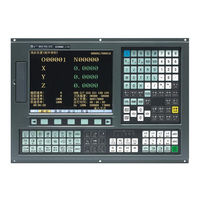
GSK GSK218MC-V User Manual (336 pages)
Brand:
GSK
| Category:
Control Systems
| Size: 6.47 MB
Table of Contents
Table of Contents
11
Volume I Programming
17
Chapter One Squency Programming Compilation Schedule
18
GSK218MC Series PLC Specification
18
Concept of the Sequence Programming
18
Distribution Interface (Step One)
19
Ladder Diagram Compilation (Step Two)
19
Sequence Programming Debugging (Step 3)
19
Chapter Two Sequence Programming
21
Performance Process of Sequence Programming
21
Cycle Performance
22
Priority Sequence of the Execution
22
St Level, the 2 Nd Level)
22
Input/Output Signal Treatment
25
Input Signal Treatment
25
Treatment of the Output Signal
26
Distinguish of Signal State between
26
St Level and 2 Nd Program
26
Interlocking
27
Chapter Three Plc Address
29
Machine → PLC Address (X)
29
Address on I/O Input
30
Address on MDI Panel
30
PLC → Address of Machine Tool Side (Y)
32
Y Address on I/O Output Port
32
PLC →CNC Address (G)
34
CNC →PLC Address (F)
35
Internal Replay Address (R)
35
Nonvolatile Relay Address (K)
36
Information Display Request Address (A)
36
Counter Address (C)
37
Counter Preset Value Address (DC)
37
Timer Address (T)
37
Presetting Value Address of Timer (DT)
37
Data Table Address (D)
37
Address Mark (L)
37
Subprogram Number (P)
38
Chapter Four Plc Basis Code
39
RD, RD.NOT, WRT, and WRT.NOT Codes
39
AND, AND.NOT Codes
40
OR, OR.NOT Codes
41
OR. STK Code
41
AND. STK Code
42
Chapter Five Plc Function Code
43
END1 (the 1 Level Sequence Program End)
44
END2 (the 2 Sequence Program End)
44
CALL (Call Subprogram)
44
CALLU (Unconditionally Call Subprogram)
45
SP (Subprogram)
46
SPE (End of Subprogram)
46
SET (Replacement/Setting)
47
RST (Resetting)
47
JMPB (Mark Number Skip)
48
LBL (Mark Number)
49
TMR (Timer)
49
TMRB (Fixed Timer)
50
Tmrc (Timer)
51
CTR (Binary Counter)
52
DEC (Binary Decoding)
54
COD (Binary System Code Conversion)
55
COM (Concentric Line Control)
56
COME (Concentric Line Control End)
57
ROT (Binary Rotation Control)
57
SFT (Register Displacement/Shifting)
60
DIFU (Rising Edge Detection)
61
DIFD (Descending Edge Detection)
62
COMP (Comparison of Binary Number)
63
COIN (Consistency Comparison)
64
MOVN (Data Transmission)
64
MOVB (Transmission of 1 Byte)
65
MOVW (Transmission of Two Bytes)
66
XMOV (Binary Indexed Data Transmission)
67
DSCH (Binary Data Index)
68
ADD (Binary Addition)
69
SUB (Binary Subtraction)
70
ANDF (Bit-By-Bit AND)
71
ORF (Bit-By-Bit OR)
72
NOT (Bit-By-Bit NOT)
73
EOR (Exclusive OR)
74
Chapter Six Compilation Limit of Ladder Diagram
76
Volume II Operation Explanation
78
Chapter One Plc Interface Display
80
GSK218MC Series Automatic Operation in PLC on
80
Program-Controlled Interface Display
80
INFO Interface
80
PLCGRA Interface
82
PLCPAR Interface
82
PLCDGN Interface
83
PLCTRAE Interface
84
Chapter Two Plc Programming Operation
88
Brief
88
Basis Code
89
Operation Explanation of Ladder Diagram
90
Function Code
93
Command Table
94
Compilation Command
95
PLC Operation Steps
96
Chapter Three Plc Address and Parameter Setting
98
Nonvolatile/Hold Relay
98
Timer
100
Data List
101
Counter
102
M Function Corresponding to F Address
103
Chapter Four User Explanation of Ladder Diagram Software
106
Edit
106
Brief
106
Software Introduction
106
Software Start
106
Function Introduction
107
Software Operation
108
Toolbar
108
Selection of Figure
110
Editing of Figure
111
Ladder Diagram Note
112
Leading-Out
114
Volume III Function Explanation
116
Chapter One Controllable Axis
118
Output of Axis Movement
118
Servo Signal Ready
119
Chapter Two Operation Preparation
120
Esp
120
CNC Overtravel Signal
120
Alarm Signal
121
Selection of Operation Method
122
State Signal Output
122
Chapter Three Manual Operation
124
JOG Feed/Incremental Feed
124
Chapter Four Reference Position Return
128
Manual Reference Position Return
128
Return to Reference Position Detection Signal
129
Area Detection Signal
130
Chapter Five Automatical Operation
132
Cycle Start/ Feed Dwell
132
Resetting
134
Program Testing
135
Machine Tool Lock
135
Dry Run
135
Single Block
136
Skip Optional Block
137
Program Restart
138
Chapter Six Feedrate Control
140
Rapid Traverse Rate
140
Feedrate Override
140
Override Cancellation
141
Chapter Seven Miscellaneous Function
142
M Code Miscellaneous Function
142
S Code Miscellaneous Function
143
T Code Miscellaneous Function
144
Miscellaneous Function Lock
148
Chapter Eight Spindle Velocity Function
150
Spindle Velocity Control Method
150
Gear Spindle
150
Analog Spindle
150
Rigid Tapping
152
Chapter Nine Programming Code
154
User Macro Program
154
Canned Cycle
156
Chapter Ten Display/Setting
158
Clock Function
158
Operation Record Display
158
Help Function
158
Chapter Eleven Measuring
160
Skip Function
160
Chapter Twelve Panel Lock Setting
162
Volume IV
173
Installation & Connection
173
Chapter One System Configuration & Installation
175
System Composition
175
System Installation and Connection
175
CNC System Appearance Installation Dimension Figure
177
Additional Panel Figure
183
Chapter Two Connection between Equipments
185
Connection Diagram of External System
185
Layout of Interface Position
185
Pulse Servo Connection Schematic
187
Bus Servo Connection Schematic
188
Five-Linkage Servo Connection Schematic Using Bus Technology
189
Connection between System and Drive Unit
190
System Interface Figure
190
Interface Signal List
190
Signal Explanation
191
Cable Connection Figure
193
GSK-LINK Cable Connection Figure
195
External Wiring Figure of GL100 Bus Extension Module
197
RS232 Standard Series Interfaces
198
Connection of Mpg/Hand Unit
199
Interface Signal Figure
199
Explanation of Interface Signal
199
Connection of Spindle Unit
202
Interface Signal Table
202
Explanation of Interface Signal
202
Cable Connection Figure
203
System Power Interface
205
External Power Control Interface
205
Connection of Communication Cable
205
Chapter Three I/O Interface of Machine Control
207
Interface Signal Table
207
Interface Input
207
Interface Circuit Input
207
Interface Circuit of Hand Unit
208
Interface Definition of Signal Input
209
Interface Output
212
Interface Circuit Output
212
Interface Definition of Signal Output
213
Chapter Four Machine Debugging
215
Debugging Preparation
215
System Power-ON
216
ESP and Limit
216
Gear Ratio Adjustment
218
Backlash Compensation
220
Setting Related with Drive Unit
221
Machine Tool Pitch Compensation
222
Mechanical Zero Return (Machine Zero Return)
229
Mechanical Zero Return in Pulse Method
230
Servo Zero Return Function Setting of Bus Type
233
Input/Output Signal Control of Spindle Positive/Negative
239
Spindle Automatic Gear-Shift Control
241
External Cycle Start & Feed Hold
243
External Editing Lock and the External Operation Panel Lock
244
Cooling, Lubrication and Chip-Removal Control
244
Setting Related to Feedrate
245
Setting Related with Tapping Parameter
247
Setting for the
250
Th Axis
250
Setting about the Bus Servo
252
Appendix
259
Appendix I Ladder Diagram Usage Guide of Gsk218Mc Series with Cone Type Tool-Magazine
261
Cautions When Using the Cone Type Tool-Magazine Ladder Diagram
261
Configuration and Definition of PLC I/O Address and Internal Software Components
261
The Usage and Maintenance of the Cone Tool Magazine
286
The Macro Note Matching with the Cone Tool Magazine
294
Appendix II Laddar Diagram Use Guide of Gsk218Mc Series Matching with Disc Tool Magazine
297
The Application Precautions of the Disc Tool Magazine
297
The Configuration and Definition of the PLC I/O Address and Internal Soft Component
297
The Usage and Maintenance with Manipulator Tool Magazine
326
Macro Note with Disk Tool Magazine
333
II. that the “%” Takes One Single Line Means that the M Code Information
335
Appendix III File Format of Ladder Diagram Configuration
335
F Signal and Meaning of the M Code M00
335
That the "%" Takes One Single Line Means that the M Code Information Storage Is End
335
The Code and Meaning of the X Signal X0.0
335
The Code and Meaning of the y Signal Y0.0
336
The Code and Meaning of the K Signal K6.0
336
The Code and Meaning of the a Signal A0.0
336
End//End Mark
336
Advertisement
Advertisement
Related Products
GSK GSK218MC
GSK GSK218MC-U1
GSK GSK218MC-H
GSK GSK218MC-H2
GSK GSK988TB
GSK GSK983Ta-H
GSK GSK983Ta-V
GSK GSK928TE
GSK GSK983M-H
GSK GSK983M-V
GSK Categories
Control Systems
Medical Equipment
Servo Drives
Engine
Controller
More GSK Manuals
Login
Sign In
OR
Sign in with Facebook
Sign in with Google
Upload manual
Upload from disk
Upload from URL