Sign In
Upload
Manuals
Brands
Giga-tronics Manuals
Measuring Instruments
8501A
Giga-tronics 8501A Manuals
Manuals and User Guides for Giga-tronics 8501A. We have
1
Giga-tronics 8501A manual available for free PDF download: Operation & Maintenance Manual
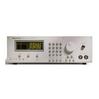
Giga-tronics 8501A Operation & Maintenance Manual (262 pages)
8500A Series Peak Power Meters
Brand:
Giga-tronics
| Category:
Measuring Instruments
| Size: 2.72 MB
Table of Contents
Table of Contents
3
About this Manual
11
Introduction
11
Conventions
13
Record of Manual Changes
15
Special Configurations
17
1 • Introduction _______________________________________________________
19
Description
19
Environmental Requirements
20
Items Furnished
20
Items Required
20
Tools and Test Equipment
20
Cooling
20
Cleaning
20
Receiving Inspection
20
Returning an Instrument
21
System Specifications
22
Default Settings
26
Operation
27
General
27
Installation
27
Figure 2-1 Power Connector
28
Figure 2-2 PCB Voltage Selector and Fuse Holder
29
PCB-Oriented Voltage Selector and Fuse Holder
29
Figure 2-3 VDE Voltage Selector and Fuse Holder
30
VDE Type Voltage and Fuse Holder
30
List of Figures
28
Figure 2-4 Model 8502A Rear Panel
31
Rear Panel Description
31
Figure 2-5 Model 8502A Front Panel
33
Front Panel Description
33
Operation
36
Power on Self-Test (POST)
36
Warm up Time and Temperature
36
Mode Selection
37
CW Mode
37
Peak Mode
37
Graph Mode
39
Self-Calibration and Auto-Zeroing
40
Self-Calibration Procedure
40
Self-Calibration Failures
41
Auto-Zero Function
41
Measurement Procedures
42
Frequency Correction, Cal Factor, and Db Offset
42
PROM Frequency Correction
42
User-Supplied Cal Factor
43
CW Power Measurement
44
Peak Power Measurement
45
Figure 2-6 Typical Single Channel Peak Power Display
47
Figure 2-7 Typical Initial Graph Mode Display
49
Peak Power Measurements Using the Graph Mode
49
Figure 2-8 Typical Cursor Sub-Mode Digital Plot
50
Figure 2-9 Typical Pulse Sub-Mode Digital Plot
52
Pulse Parameters Sub-Mode Functions
52
Figure 2-10 Typical Marker Sub-Mode Digital Plot
54
Marker Sub-Mode Functions
54
Digital Plotting of Graphic Data
56
Plotters Supported
56
Procedure for Making Plots
56
Dual Channel Measurements
58
CW, CW Measurements
58
Peak, Peak Measurements: Method
58
Peak, Peak Measurements: Method
59
Figure 2-11 Typical Signal Timing
59
Peak, CW Measurements
60
Power Ratio Measurements
61
Figure 2-12 Typical Peak Power Ratio Display
61
Figure 2-13 Typical Good & Bad Cursor Delay Settings
62
High Power Measurement Procedures
63
Figure 2-14 Detector to a High-Power Coupler Setup
64
Figure 2-15 Detector to High Power Attenuator Setup
64
High Power Relative Measurements (8502A Only)
65
High Power Measurements
63
Power Warning - Max/Min Power Limits
63
Special Capabilities of the PPM
66
Reference Delay
66
Single Pulse Measurements
66
Single Pulse Measurement Using Internal Trigger
66
Figure 2-16 Typical Pulse with -10 Dbm Trigger Level
66
Single Pulse Measurement with an External Trigger
67
Figure 2-17 Typical Pulsed Swept Measurement System
68
Swept Peak Power Measurements
68
List of Tables _________________________________________________________
70
Self-Testing the 8500A
70
Table 2-1 Self-Test Error Flags
70
Frequency Display Disable/Enable
71
Non-Volatile Memory
71
Memory Features
71
B Peak Power Meter Emulation
73
Introduction
75
3 • Remote Operation __________________________________________________
76
Remote Operating Modes
76
Front Panel Menus
77
Remote and Local Lockout Functions
78
Command String Format
86
GPIB Command Descriptions
88
Common Mode Functions
89
Measurement Data Correction
91
Mode Selection and Control
95
Commands for Retrieving Data from the PPM
97
Graph Mode GPIB Operation
98
Marker Timing Measurements
100
Manual Marker Placement/Timing Measurement Commands
103
Window and Cursor Control Commands
105
Commands to Output Graphic Data to a Controller
107
Plotting Commands
108
Programming Notes
109
Service Requests and Serial Poll
110
Error Conditions
111
B Emulation
112
Status Code Decimal Values
115
Table 3-1 Status Code Values and Conditions
115
Summary of Bus Functions
117
Normal PPM Operation
117
PPM Stand Alone Plot Operation
117
Table 3-2 Summary of Bus Functions
117
GPIB Command Summary
118
Table 3-3 GPIB Commands Format
118
1018B Emulation Commands
126
Data Formats
126
Table 3-4 1018B Emulation Commands Format
126
Theory of Operation
127
Introduction
127
System Description
127
Figure 4-1 Series 8500A System Block Diagram
128
Power Supply PC Assembly (A2)
129
Table 4-1 A2 Test Points
129
Figure 4-2 Gpib/Cal Control (A3) Block Diagram
130
GPIB/CAL Control PC Board (A3)
130
Figure 4-3 Voltage to Current Converter
132
Table 4-2 A3 Test Points
133
CPU PC Assembly (A4)
134
Figure 4-4 CPU (A4) Block Diagram
134
Table 4-3 A4 Test Points
137
Digital Delay PC Assembly (A5)
138
Figure 4-5 Digital Delay (A5) Block Diagram
138
Figure 4-6 Timing Diagram - Delay Board Functions
140
Table 4-4 A5 Test Points
145
Analog PC Assembly (A6/A7)
146
Figure 4-7 Analog PC (A6/A7) Block Diagram
146
Table 4-5 A6/A7 Analog Test Points
149
Figure 4-8 Front Panel Interface (A8) Block Diagram
150
Front Panel Interface PC Assembly (A8)
150
Table 4-6 A8 Interface Assembly Test Points
152
Calibrator PC Assembly (A12)
153
Figure 4-9 Detector Calibrator (A12) Block Diagram
153
Testing and Calibration
157
General
157
Performance Testing
158
Equipment Required
158
Table 5-1 Required Test Equipment
158
Calibrator Return Loss Test
159
Calibrator Output Level Test
159
Instrument Plus Power Detector Linearity Test
159
Power Linearity Test Setup
160
Figure 5-1 Power Linearity Test Setup
160
Delay Accuracy Test
162
Figure 5-2 Delay Accuracy Test Setup
162
Analog Output Accuracy Test
163
Voltage Proportional to Frequency Test
163
Detector Return Loss Test
163
Plotter Output/Ieee-488 Interface
163
Calibration Procedures
164
Figure 5-3 Model 8501A/8502A Calibration Components
165
Calibration Equipment Required
166
Preset Conditions
166
Table 5-2 Required Calibration Test Equipment
166
A2 Regulator Board
167
A8 Front Panel Interface Board
168
Initialization
168
A6/A7 Analog Board
169
A3 GPIB/CAL Control Board
171
A4 CPU Board
171
A5 Digital Delay Board
172
Figure 5-4 Typical PPM Digital Delay Display
172
Figure 5-5 Typical PPM Display with A5R30 at Max Cw
173
Figure 5-6 Typical PPM Display W/Smooth Rise Time
173
Table 5-3 Multiples of 25.6 Ns
174
External Interface
175
Figure 5-7 Typical PPM Sync Output Scope Display
175
Volume Adjust
176
Maintenance
181
Introduction
181
Periodic Maintenance
181
Required Test Equipment
182
Table 6-1 Required Test Equipment
182
Troubleshooting
183
Equipment Required
183
Power-On Failure
183
Parts Lists
187
Introduction
187
Parts Lists for Series 8500A Peak Power Meters
187
8501A Peak Power Meter
187
8502A Dual Input Peak Power Meter
188
20512-A00 8501A Chassis Assy
189
20513-A00 8502A Chassis Assy
190
21147 Front Sub Panel Assy 8502A
190
21148 Rear Panel Assy 8502A
190
20879 El Display Module Assembly
193
20879-A00 el Display Module Sub Assy
193
16869 Delay Line Assembly
193
Interconnect Pcb Assy
194
Pcb Assy, Power Supply
196
21014 Pcb Assy Gpib/Cal Control 8500
199
21014-A00 Pcb Assy Pre-Wave,Gpib
199
16878 Pcb Assy., Cpu
202
16878-A00 Pcb Assy Pre-Wave, Cpu
203
16685 P.C. Assy, Digital Delay
205
16685-A00 Pcb Assy Pre-Wave, Dig. Delay
205
Analog Pcb Assy
210
A00 Pcb Assy Pre-Wave, Analog
211
Pcb Assy, Fr Pnl Interface
216
20526-001 Pc Board Assy, Front Panel
219
Assy, 1Ghz Calibrator Type N
220
List of Manufacturers
222
Diagrams
229
Introduction
229
Applicability
229
Table 8-1 Series 8500A Diagrams
229
A• Summary of Commands ____________________________________________
231
A.1 Introduction
231
A.3 CW Mode Commands
232
A.5 Graph Mode Commands
233
A.5.3 Pulse Sub-Mode Commands
234
A.6 Dual Channel Operation
235
B • Menu and Memory Keys ____________________________________________
237
B.1 Introduction
237
B.2.2 1018B Emulation Mode Functions
239
B.3 Memory Key Displays
240
100 C • Display Formats ___________________________________________________
241
C.1 General
241
Model 8501A/8502A Peak Power Meter, DWG# 20522
242
500 D • RF Detectors ______________________________________________________
243
D.1 Introduction
243
D.2 Detector Specifications
244
Figure D-1 Op-Amp Equivalent of Pre-Amp Circuit
246
D.3 Electrical Description
246
Figure D-2 Pre-Amplifier/Line Driver Schematic
247
Figure D-3 PROM PC Assembly Schematic
248
D.3.2 PROM PC Assembly
248
D.4 Detector Maintenance
249
D.5.1 Disassembly of Detectors
250
D.5.3 Reassembly of Detectors
251
Figure D-4 Detector Disassembly and Assembly Details
252
E.1 Introduction
253
E.3 Option 03: Rear Panel Connections
254
Index
255
Advertisement
Advertisement
Related Products
Giga-tronics 8003
Giga-tronics 8502A
Giga-tronics 8650A Series
Giga-tronics 8650B Series
Giga-tronics 80350A
Giga-tronics 80353A
Giga-tronics 80354A
Giga-tronics 80355A
Giga-tronics 80351A
Giga-tronics 80352A
Giga-tronics Categories
Multiplexer
Amplifier
Switch
Measuring Instruments
Synthesizer
More Giga-tronics Manuals
Login
Sign In
OR
Sign in with Facebook
Sign in with Google
Upload manual
Upload from disk
Upload from URL