Table of Contents
Advertisement
Quick Links
Manual Part Number:
20790
Revision Level:
C
Configuration Code:
27
Print Date:
November 1998
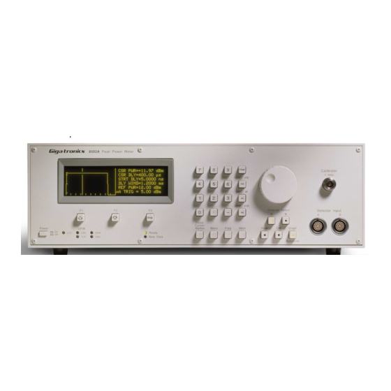
Operation & Maintenance Manual
Series 8500A
Peak Power Meters
. . . . . . . . . . . . . . . . . . . . . . . . . . . . . . . . . . . . . . . . . . . . . . . Certified Product
ISO 9001
. . . . . . . . . . . . . . . . . . . . . . . . . . . . . . . . . . Certified Process
Registra: BSI, Certification No. FM 34226, Registered 04 June 1996
Giga-tronics Incorporated
4650 Norris Canyon Road
San Ramon, California 94583
Telephone (925) 328-4650 or (800) 726-4442
Telefax (925) 328-4700
Customer Service: Telephone (800) 444-2878
Telefax (925) 328-4702
Web Site: www.gigatronics.com
Advertisement
Table of Contents

Related Manuals for Giga-tronics 8502A


Summary of Contents for Giga-tronics 8502A
- Page 1 ........Certified Process Registra: BSI, Certification No. FM 34226, Registered 04 June 1996 Giga-tronics Incorporated 4650 Norris Canyon Road...
- Page 2 The Series 8500A includes two models: The single-channel Model 8501A and the dual-channel Model 8502A. Apart from the number of sensors they support, the two models are identical. Both models are referred to in this manual by the general term 8500A, except where it is necessary to...
-
Page 3: Table Of Contents
Table of Contents About This Manual ............Conventions . - Page 4 2.12 High Power Measurement Procedures ......... 2-37 2.12.1 High Power Relative Measurements (8502A only) ......2-39 2.13 Special Capabilities of the PPM .
- Page 5 Preface 3.6 Status Code Decimal Values ..........3-41 3.7 Summary of Bus Functions.
- Page 6 8502A DUAL INPUT PEAK POWER METER........
- Page 7 Preface CPU Circuit Schematic (A4), DWG# 16879 ........8-16 Digital Delay PC Assy (A5), DWG# 16685 .
- Page 8 Series 8500A Peak Power Meters E • Options ___________________________________________________________ E.1 Introduction ............. . . E.2 Option 01: Rack Mount Kit .
- Page 9 Model 8502A Rear Panel ........
- Page 10 Series 8500A Peak Power Meters List of Tables _________________________________________________________ Table 2-1 Self-Test Error Flags ..........2-44 Table 3-1 Status Code Values and Conditions .
-
Page 11: About This Manual
About This Manual This manual contains the following chapters and appendices to describe the operation and maintenance of Series 8500A Peak Power Meters: Preface: In addition to a comprehensive Table of Contents and general information about the manual, the Preface also contains a record of changes made to the manual since its publication, and a description of Special Configurations. - Page 12 Series 8500A Peak Power Meters Manual No. 20790, Rev C, November 1998...
-
Page 13: Conventions
Conventions The following conventions are used in this product manual. Additional conventions not included here will be defined at the time of usage. Warning WARNING The WARNING statement is enclosed in double lines and centered in the page. This calls attention to a situation, or an operating or maintenance procedure, or practice, which if not strictly corrected or observed, could result in injury or death of personnel. - Page 14 Series 8500A Peak Power Meters Symbols Block diagram symbols frequently used in the manual are illustrated below. Course Fine STEP ATTEN Pulse YIG-Tuned Mixer Step PIN-Diode Switch Modulator Oscillator Attenuator Leveler PASS RF Level Voltage- Digital to Fixed Filter Detector Coupler Controlled Analog...
-
Page 15: Record Of Manual Changes
Record of Manual Changes This table is provided for your convenience to maintain a permanent record of manual change data. Corrected replacement pages will be issued as Technical Publication Change Instructions, and will be inserted at the front of the binder. Remove the corresponding old pages, insert the new pages, and record the changes here. - Page 16 Series 8500A Peak Power Meters Manual No. 20790, Rev C, November 1998...
-
Page 17: Special Configurations
Special Configurations When the accompanying product has been configured for user-specific application(s), supplemental pages will be inserted at the front of the manual binder. Remove this page and replace it with the furnished Special Configuration supplemental page(s). Manual No. 20790, Rev C, November 1998... - Page 18 Series 8500A Peak Power Meters Manual No. 20790, Rev C, November 1998...
-
Page 19: Description
The Model 8501A has a single detector input; Model 8502A has dual detector inputs for making ratio measurements. All technical and operation descriptions in this manual apply equally to both models unless otherwise stated. -
Page 20: Environmental Requirements
Check the shipping carton for evidence of physical damage and immediately report any damage to the shipping carrier. Each Giga-tronics instrument must pass rigorous inspections and tests prior to shipment. Upon receipt, its performance should be verified to ensure that operation has not been impaired during shipment. The performance verification procedure is described in Chapter 5 of this manual. -
Page 21: Returning An Instrument
1.1.8 Returning an Instrument If you are returning an instrument to Giga-tronics for any reason, including service, first contact Giga-tronics Customer Service at (800) 444-2878 or Fax at (925) 328-4702 so that a return authorization number can be assigned. You can also contact Customer Service over their e-mail address repairs@gigatronics.com. -
Page 22: System Specifications
Series 8500A Peak Power Meters System Specifications Frequency Range 30 MHz to 40 GHz depending on detectors (See the Detector Specifications in Appendix D) Power Range (Direct input to detector): Pulse Mode: -20 to +20 dBm CW Mode: -40 to +20 dBm Absolute Maximum Limit: +23 dBm (200 mW) Accuracy... - Page 23 Introduction Trigger Delay Range: 0 to 200 ms, using either the Data Entry keyboard or the spin knob Resolution: 0.1 ns Accuracy: 0 to 10 ms, ±0.2% ±1 ns; 10 ms to 5 ms, ±0.1%; 5 ms to 200 ms, ±0.01% Triggering Modes Internal: -20 dBm to +16 dBm limited to >2 dB and <20 dB below the peak...
- Page 24 Series 8500A Peak Power Meters Auxiliary Inputs/Outputs Monitor: Provides a voltage proportional to the detected RF envelope. Rise time is typically 20 ns, output impedance is nominally 50 ohms. Analog Output Coefficient: 100 mV/dB ±0.5 mV (0 V = 0 dBm) Offset: ±10 mV Trigger Input:...
- Page 25 Conforms to EIA RS-310 Standard for a 19-inch rack. Weight: Model 8501A: 12 kg (26 lbs) Model 8502A: 13 kg (28 lbs) Depending upon requirements, the following software versions and enhancements apply (See Table 1-1). Table 1-1: 8500A Functions Related to Software Versions...
-
Page 26: Default Settings
Series 8500A Peak Power Meters Default Settings Factory-programmed settings of various user definable functions have the following defaults whenever there have been no changes made in the settings by the operator during any testing routines. Function Default Setting Averaging CW: 4 samples; Peak: 4 samples Internal Trigger Level (A &... -
Page 27: Operation
NOTE: In the remainder of this chapter except where specified as the Model 8501A or 8502A, the instrument may be referred to as the PPM (Peak Power Meter). 2.2 Installation The unit is set at the factory for operation at the normal supply voltage for the country in which it is sold. -
Page 28: Figure 2-1 Power Connector
Series 8500A Peak Power Meters NOTE: The 8500A may be furnished with the PC-oriented voltage selector and fuse holder described next, or the VDE-approved fuse holder described in the following pages. Refer to the appropriate type of voltage selector and fuse holder for your power meter. CAUTION The instrument may be damaged if you turn it on while the voltage selector and fuses are incorrect for the applied line voltage. -
Page 29: Pcb-Oriented Voltage Selector And Fuse Holder
Operation 2.2.1 PCB-Oriented Voltage Selector and Fuse Holder The number on the selector card, visible through the window, indicates the nominal line voltage to which the power meter must be connected. The line voltages and fuse ratings are: Line Voltage Fuse Rating 100/120 Vac, ±10%, 50, 60 or 400 Hz ±5% 1.0 AMP Slo-Blo... -
Page 30: Vde Type Voltage And Fuse Holder
Series 8500A Peak Power Meters 2.2.2 VDE Type Voltage and Fuse Holder The VDE-approved voltage selector and fuse holder are contained in a covered housing directly above the ac power connecter. The line voltages and fuse ratings are: Line Voltage Fuse Rating 100/120 Vac, ±10%, 50, 60 or 400 Hz ±5% 1.0 AMP Slo-Blo... -
Page 31: Rear Panel Description
The Series 8500A power meter rear panel controls and interface connections are described in this section. The boxed numbers in the diagram correspond to the boxed numbers in the description. The Model 8501A will have single-channel inputs while Model 8502A will have Channel A and Channel B inputs as shown in Figure 2-4. - Page 32 Series 8500A Peak Power Meters Detector Input These channel A and B inputs (single input in the 8501A) will be hole cover plates unless Option 03 (Rear Panel Connection) has been ordered. With Option 03, the Detector Input and Calibrator will be relocated from the front to the rear panel. The Calibrator connection will be above the Serial/Code number label on the right side of the rear panel.
-
Page 33: Front Panel Description
Figure 2-5 correspond to the boxed numbers in the description. The Peak, CW, and Graph keys in both power meter models, and the Detector Select A and B keys of the Model 8502A contain lights in the center of the buttons to indicate when the functions are active. - Page 34 Series 8500A Peak Power Meters Clear The CLEAR key exits from a menu, but it clears erroneous entries while entering data. Units: ns/dBm mW This key enters pulse timing parameters in nanoseconds. The dBm mW function enters a power parameter in either dBm or milliwatts. µs/dB W This key enters pulse timing parameters in microseconds.
- Page 35 Ratio Mode (see the Power Ratio Measurement Procedures in Section 2.10.5). When the 8502A Ratio Mode is in use, the A and B keys call up a menu so that the type of signal (CW or Peak) can be specified for the selected channel. This is useful for determining the ratio between a CW and a Peak signal.
-
Page 36: Operation
DETECTOR INPUT detector cable (P/N 16956-XXX, where XXX defines the specified length of the cable) supplied with the system. If a Model 8502A is to be used, detectors should be connected to channel A and B inputs for dual channel operation. -
Page 37: Mode Selection
If a menu is being displayed and you want to exit it and go to the CW Mode press [CLEAR] [CW]. If the 8502A is in the Ratio mode, selecting CW will cancel RATIO and the 8502A will display the CW power of channel A. - Page 38 Ready light will not be on. If a Model 8502A is being used, the routine will ask whether internal triggering is to be driven by inputs from channel A or channel B. Press the appropriate Detector Select [A] or [B] key. To select the Internal...
-
Page 39: Graph Mode
[PEAK] or [GRAPH] whenever desired. The only exception to this is when an 8502A is being used in the dual channel mode of operation since the Graph Mode does not allow dual channel operation. If a dual channel function is being used and it is desired to switch to the Graph Mode, single channel operation must first be selected. -
Page 40: Self-Calibration And Auto-Zeroing
If a Model 8501A is in use, press [CLEAR] to return the routine to the data display (the last mode of operation). If the Model 8502A is being used, press [CLEAR] to bypass the channel A calibration and go to the channel B calibration. -
Page 41: Self-Calibration Failures
[MENU] [F3] to get to the Self-Cal/Auto-Zero menu. Then press [F2] to Auto-Zero and follow the displayed prompts. If the Model 8502A is in use, channel A must be auto-zeroed before channel B. If desired, channel A can be bypassed by pressing [CLEAR] and going directly to channel B. -
Page 42: Measurement Procedures
Series 8500A Peak Power Meters 2.8 Measurement Procedures 2.8.1 Frequency Correction, Cal Factor, and dB Offset The Frequency Correction and Offset functions enhance measurement accuracy, and compensate for detector amplitude and frequency response variations as well as devices residual to the test setup. Frequency correction is selected in Menu-3. -
Page 43: User-Supplied Cal Factor
PROM might be out of date. To activate the Cal Factor feature of the system, press [MENU] (3) [F3] [F3]. If the dual channel 8502A is being used, you will be asked to select a channel. Select A or B as appropriate. -
Page 44: Cw Power Measurement
Auto-Zero the detector by pressing [MENU] (1) [F3] [F2] [UNITS], or, if only channel B of a Model 8502A is to be zeroed, press [MENU] (1) [F3] [F2] [CLEAR] [UNITS]. A beep indicates that a successful auto-zero has been accomplished. A double beep indicates either there was RF power present at the detector input or there could be a failure. -
Page 45: Peak Power Measurement
The readout will be displayed in large alphanumeric characters. For the following procedure, assume that either a single channel Model 8501A is being used or just channel A or channel B of the dual channel 8502A. Autoscaling Procedure - Internal Trigger Connect the detector(s) to the PPM and allow it to warm up for 30 minutes. - Page 46 Series 8500A Peak Power Meters Waiting for trigger on A (or B) Detector Signal F1 for Trig Mode or Level Change F3 for CW Data Display If you still desire to Autoscale at this point, the easiest thing to do is to increase the RF power until the power at the detector input is greater than the trigger level.
-
Page 47: Figure 2-6 Typical Single Channel Peak Power Display
For the purposes of this procedure, assume that either the single channel 8501A or only channel A of the dual channel 8502A is being used. The procedures for channel B of the 8502A are almost the same as those for channel A. However, if it is desired to use the Internal Trigger function with channel B, this must be selected by using the MENU key as described under Internal Triggering in Section 2.6.2. - Page 48 Series 8500A Peak Power Meters time. The easiest way to ensure that all of the Peak Mode settings are at their default values is to select Peak operation after initializing the current setup. Press [MEM] (3) [F1] [PEAK]. The display should be similar to Figure 2-6. A display of hyphens in place of a number in the power read-out portion of the display indicates that the power being sampled is below the measurement range of the system.
-
Page 49: Figure 2-7 Typical Initial Graph Mode Display
Operation 2.8.6 Peak Power Measurements Using the Graph Mode It is recommended that you read the basic information pertaining to the Graph Mode in Section 2.6.3 for a better understanding of this function. The initial Graph Mode (Cursor sub-mode) display looks something like that shown in Figure 2-7. -
Page 50: Figure 2-8 Typical Cursor Sub-Mode Digital Plot
Series 8500A Peak Power Meters 2.8.8 Cursor Sub-Mode Functions The Cursor sub-mode is convenient for changing the timebase parameters of the display (the CurSoR DeLaY, the STaRT DeLaY, and the DeLaY WINDow), the scaling of the display (the REFerence PoWeR), and the trigger level if the PPM is in internal trigger mode. - Page 51 This display indicates the present triggering mode of the PPM. TRIG LEV = -10 dBm (A TRIG = -10 dBm in the 8502A) is the default setting. It means that the PPM will trigger when the leading edge of the RF pulse rises above -10 dBm at the (channel A) detector input. B TRIG = (8502A only) indicates that the PPM is triggering off the channel B detector.
-
Page 52: Figure 2-9 Typical Pulse Sub-Mode Digital Plot
Series 8500A Peak Power Meters 2.8.9 Pulse Parameters Sub-Mode Functions Commonly used timing measurements required when analyzing pulsed RF/microwave signals are: • Pulse Width • Rise time • Fall time • Peak Power • Repetition Rate The pulse parameter readout allows the first four of these parameters to be measured directly by the PPM and displayed on the readout window. - Page 53 Operation The last line of the display will show the prompt: Enter Start %. Enter the desired Start % setting through the numeric keypad. Press [UNITS]. The Enter Start % indication will change to: Enter End %. Enter the desired End % value and press [UNITS]. (Repeated pressing of any Units key will toggle the display between the Start and End values.) To change the start and stop percentages for rise and fall times, move the cursor to the appropriate line and repeat Steps 3 through 7.
-
Page 54: Marker Sub-Mode Functions
Series 8500A Peak Power Meters 2.8.10 Marker Sub-Mode Functions The Marker sub-mode is another completely independent way to read the time difference between user defined points on the pulse waveform. It may, at first, seem redundant with the Pulse parameter mode. The Marker sub-mode, however, treats the 100% power point differently, and reads the differences between four user-defined points on the waveform. - Page 55 Operation Move the cursor (using the up or down arrow keys) to the MKR 2-1= line on the display. The current marker percentage setting for marker 1 will be displayed. Enter the desired Marker 1 percentage through the numeric keypad, using any Units key to terminate the entry.
-
Page 56: Digital Plotting Of Graphic Data
Series 8500A Peak Power Meters 2.9 Digital Plotting of Graphic Data 2.9.1 Plotters Supported The PPM is configured to provide direct output of Graph Mode information for hardcopy recording on a digital plotter. This is done without the necessity of using a computer or GPIB controller. The following plotters (and any other 100% compatible plotters) are supported: Hewlett-Packard Model 7440A Hewlett-Packard Model 7470A... - Page 57 Operation Enter the Part number as follows: [MENU] (5) [F2] [n] [UNITS] (n is a number up to 12 digits). The date and time are always plotted. The date and time are obtained from the internal, real-time clock of the PPM which is kept alive by a battery when the instrument is turned off. If it is desired to check and/or change the date and time before plotting, press [MENU] (5) [F3] [F3] (if clock is correct) or, to change the clock, [MENU] (5) [F3] [F1] [mmddyy] [UNITS] [hhmmss] [UNITS] [F3]...
-
Page 58: Dual Channel Measurements
Series 8500A Peak Power Meters 2.10 Dual Channel Measurements Dual channel measurements are available only when using the Model 8502A power meter. The dual channel capability of the Model 8502A provides two very useful functions. These are: • Display of power measured by two channels simultaneously. -
Page 59: Peak, Peak Measurements: Method
Operation To change the Cursor Delay for channel B, press the up or down arrow key. The spin knob can then be used to alter the channel B Cursor Delay. To lock out the spin knob and keyboard, press any UNITS key. To reactivate the spin knob and keyboard, press the up or down arrow key. If there are any difficulties due to timing factors, it is recommended that External Triggering be used. -
Page 60: Peak, Cw Measurements
Series 8500A Peak Power Meters Connect the channel A detector to the RF source (port) that is believed to be generating a pulse before the second source (port) to be measured (i.e. Measurement Port 1). If the pulses of the two sources are coincident, use either port. -
Page 61: Power Ratio Measurements
Operation 2.10.5 Power Ratio Measurements To make ratio measurements, the power measured by both channels must be within the specified power measurement range of the PPM system. When operating in CW, this power range is -40 to +20 dBm. In the Peak Mode, this power range is -20 to +20 dBm. -
Page 62: Figure 2-13 Typical Good & Bad Cursor Delay Settings
Series 8500A Peak Power Meters Verify that the Cursor Delay setting is adequate for both channels by switching to the other channel. Use the same Start, Window, and Cursor Delays as in the first channel. If the pulses occurred at the same time, the Cursor would be close to the center of the pulse sampled by the other channel (see Figure 2-13). -
Page 63: High Power Measurements
Operation 2.11 High Power Measurements One of the most important things to remember when using the PPM is that it employs balanced, zero bias, Schottky diode detectors as power detectors. Due to this highly sensitive, highly accurate configuration, the maximum power that the detectors can handle before burning out is +23 dBm (200 mW). -
Page 64: Figure 2-14 Detector To A High-Power Coupler Setup
Figure 2-15. Detector to High Power Attenuator Setup Auto-Zero the PPM by pressing [MENU] (1) [F3] [F2] [UNITS]. If a dual channel 8502A is being used, follow the prompts given on the display. Select any Units key or CLEAR as necessary to Zero the desired channel(s). -
Page 65: High Power Relative Measurements (8502A Only)
To enter the Offset, press [MENU] (3) [F1] [nn.nn] [dBm]. Where nn.nn is the Offset desired. For channel B offset on the 8502A, use F2 instead of F1. When the Offset feature is in use, this will be shown on the display by an asterisk (*) next to the FREQ or CF indication. -
Page 66: Special Capabilities Of The Ppm
Series 8500A Peak Power Meters 2.13 Special Capabilities of the PPM 2.13.1 Reference Delay To facilitate making timing measurements relative to some event other than the trigger (such as the falling edge of a pulse), it is possible to shift the PPM time coordinates by using Reference Delay. The PPM subtracts the Reference Delay from the Cursor Delay and Start Delay, in effect shifting the zero time reference from the trigger time to a time after the trigger by the amount of the Reference Delay. -
Page 67: Single Pulse Measurement With An External Trigger
Operation Single pulse measurements cannot be made with the same accuracy as repeating pulse trains. This is primarily due to the fact that there is no way to eliminate noise that might be present in the test setup. For repetitive pulse trains, averaging can be used to eliminate errors due to noise. The procedure for making a single pulse measurement is as follows: Allow the PPM to warm up for 30 minutes, then conduct a Self-Cal. -
Page 68: Swept Peak Power Measurements
The PPM is capable of reading better than 100 pps, and the output level will be at 100 mV/dB. Swept measurements can also be made simultaneously from channels A and B of the 8502A, but the PPM’s reading rate will be somewhat slower. - Page 69 Operation knows to alter its frequency correction accordingly. The PPM then uses the proper frequency correction accordingly. The PPM then uses the proper frequency correction for the detector(s) at each discrete frequency point without necessitating any operator input or any calculations (see Section 2.8.2 more information on the interfacing of external frequency signals.) To make swept frequency measurements under pulsed conditions, equipment should be set up similar to Figure 2-17.
-
Page 70: Self-Testing The 8500A
Series 8500A Peak Power Meters 2.15 Self-Testing the 8500A Prior to performing a self-test during a testing routine (at some point after the instrument has been turned on), the detector must either be connected to the Calibrator Output on the front panel, to a 50-ohm termination, or to a signal source which has the RF power turned OFF. -
Page 71: Frequency Display Disable/Enable
Operation 2.16 Frequency Display Disable/Enable If there is some reason (such as classified testing) why it might be desired not to have the frequency of operation displayed while measurements are being taken, this can be done by using the F3 key of MENU (7) as a toggle for this function. - Page 72 Series 8500A Peak Power Meters NOTE: This selection will erase the Current selection. It is advisable to store the setup in a numbered memory before executing the command. Display Setups When one of the Display Setup features of the PPM is activated, the panel settings of the selected setup are shown on the display.
-
Page 73: B Peak Power Meter Emulation
The Giga-tronics Model 1018, 1018A, and 1018B series of peak power meters were the predecessors to the Model 8501A/8502A meters. This 1018 series was first produced in 1969, and has had several design up-grades. In 1978 Pacific Measurements, Inc. (now known as the Giga-tronics Power Measurements Division) added limited IEEE Bus capability to the 1018, but no provision was available for controlling front panel states. - Page 74 Series 8500A Peak Power Meters 2-48 Manual No. 20790, Rev C, November 1998...
-
Page 75: Introduction
Purpose Interface Bus (GPIB), and provides all of the basic information required to begin programming as easily as possible. After you are familiar with the Model 8501A/8502A Peak Power Meter (PPM) commands and functions, controlling the instrument through the GPIB should be fairly simple. A first-time user of the PPM should read the General Information in Section 3.2 before attempting to... -
Page 76: Remote Operating Modes
Series 8500A Peak Power Meters 3.2 Remote Operating Modes This section describes the various methods and modes that are used for remotely controlling the PPM through the GPIB. Typical sample programs illustrating the use of commands are provided. 3.2.1 PPM IEEE Bus Functions Remote operation of the PPM is accomplished through the GPIB under the control of a remote controller/calculator. -
Page 77: Front Panel Menus
Remote Operation 3.2.2 Front Panel Menus See Appendix B for a listing of menus that can be accessed with the front panel MENU and MEM keys. Appendix C contains illustrations of top level menu formats. Before attempting to control the PPM over the GPIB, it should be kept in mind that there are various front panel menu selections that will affect bus activity. -
Page 78: Remote And Local Lockout Functions
Series 8500A Peak Power Meters 3.2.4 Remote and Local Lockout Functions The PPM accepts commands or output data only through the bus when it is in the Remote state. It is placed in the Remote state by listen-addressing the instrument with REN asserted, per the IEEE-488 1978 standard. - Page 79 Remote Operation The instrument must always be in an output mode. It sends output information when it receives a command to initiate another output mode, or when a current output mode is completed and terminates itself. The self terminating modes are Plot, Output Temperature Difference Since Calibration, Output Status Byte, and Stand Alone Plot.
- Page 80 Series 8500A Peak Power Meters The procedure to trigger reset the PPM with the GET command consists of the following steps: Listen-address the PPM. Send the GET universal command. Talk-address the PPM. Release ATN to set the PPM in TACS. If in the Peak Mode, send the pulse to trigger the PPM.
- Page 81 Remote Operation Update Data Continuously Output Mode A string of four characters (UPDC) must be sent to the PPM to access this mode of operation: If you are using BASIC with an HP Series 200 computer, the command might look like: OUTPUT 704;...
- Page 82 Series 8500A Peak Power Meters Plot Output Mode In this mode the PPM sends HPGL plotter commands to plot a pulse on a compatible plotter. The PPM command PLOT initiates the capturing of a pulse and relevant information that will be plotted when the PPM enters TACS.
- Page 83 Remote Operation 180 ! COMMANDS WILL INITIATE THE 190 ! PPM’S PLOT ROUTINE. THE 200 ! ADDRESS OF THE PLOTTER AND 210 ! PPM MUST BE SET CORRECTLY - 220 ! IN THIS CASE THE PPM IS AT 704, 230 ! AND THE PLOTTER IS AT 706. 240 OUTPUT 704;PLCN&C$ 250 ! SEND CODE NUMBER TO PPM 260 OUTPUT 704;PLPN&P$...
- Page 84 (x and y = temperature reading digits; s = polarity): DTPAsxx.x,DTPBsyy.y(CR)(LF-EOI) This will be true with both the Model 8501A and 8502A instruments. If a detector is not present, the digit portion of the string will read +00.0. The zeros can either mean no change in temperature difference or no detector present.
- Page 85 Remote Operation When the PPM has drawn a complete pulse profile on its display, it is ready to act as a GPIB controller. When the plot routine is activated, the PPM checks to make sure that there is no other active controller on the bus.
-
Page 86: Command String Format
Series 8500A Peak Power Meters 3.2.6 Command String Format Control of the PPM is accomplished by using four-character mnemonic commands. Some of these require one or more numerical entries (arguments). The command structure is intended to be taken literally; there are no optional formats. - Page 87 Remote Operation Update Trigger Reset Mode: DBMA-012.73(CR)(LF-EOI) DBMB+002.47(CR)(LF-EOI) Update Data Continuously Mode: DBMA+016.74 DBMA+018.23 DBMA+017.34 (and so on) The actual measurement string (less terminating and delimiting characters for each data point) will always be 11 characters long. Linear Power Data Format When the PPM is in the linear power mode (as indicated in the display), the first three characters of the data string will be PWR.
-
Page 88: Gpib Command Descriptions
Frequency information can be hidden when the PPM is used for classified testing. NOTE: The Model 8501A instrument will respond to the same command sets as the Model 8502A. The only exception is that the 8501A responds only to commands relating to channel A. -
Page 89: Common Mode Functions
Remote Operation Instrument functions that take a specific amount of time to complete will be noted with an asterisk (*) in the following discussion. During the time the PPM is processing a function such as calibration, zeroing, or self test, the instrument will continue to be active on the bus. - Page 90 Series 8500A Peak Power Meters Output Status Byte Information Command STAT Output status byte. This command will only be effective when SRQ is disabled. If it is received while SRQ is enabled, a service request will be generated. Typical Program Lines: OUTPUT 704;STAT ENTER 704;A$ PRINT A$...
-
Page 91: Measurement Data Correction
Each Giga-tronics detector used in the PPM has a built-in PROM which contains frequency correction data. Depending on the mode of operation, the PPM can be instructed to automatically subtract out the frequency non-linearity error from the power measurement being made. - Page 92 Series 8500A Peak Power Meters Detector PROM Correction: External Frequency (V/GHz/Freq Ref) FPRVvv.vv,ss.ss,mm.mm (Where v, s and m are the arguments to scale the voltage input at the PPM FREQUENCY INPUT connection.) Correction to be applied for the frequency response of the detector will be determined from three user-supplied values to properly reference data in the PROM in the detector.
- Page 93 Remote Operation External Frequency (V/GHZ) and Output Frequency to Controller Command FPVOvv.vv,ss.ss,mm.mm (Where v, s, and m are the arguments required to scale the voltage input at the PPM’s rear panel FREQUENCY INPUT connection.) These are the same as described previously for FPRV. This command causes the same action as the FPRV command but in addition, asks the PPM to output to the controller the converted frequency information from the PPM’s rear panel external frequency input.
- Page 94 Series 8500A Peak Power Meters User-Defined Detector Calibration Factor Commands Detector calibration factor for channel A in dB (cc.cc): DCFAcc.cc Min Value: -9.99 dB Max Value: +9.99 dB Detector calibration factor for channel B in dB (cc.cc): DCFBcc.cc Min Value: -9.99 dB Max Value: +9.99 dB Sample Program: 10 ! THIS PROGRAM SHOWS HOW TO USE...
-
Page 95: Mode Selection And Control
Remote Operation 3.3.3 Mode Selection and Control This section describes the various modes of operation available with the PPM, with the exception of the sub-mode functions of the Graph Mode. These are described in Section 3.3.5. Commands or functions that affect a specific mode of operation are either given or referred to in the following command listings. - Page 96 Series 8500A Peak Power Meters Related Peak Power Commands AVPK Select number of averages, n, for Peak power measurements. Higher numbers will reduce noise effects and provide more stability at low power levels. (n = number from 1 to 999 - higher than 4 is recommended). TRGAsnn.nn Internal trigger level, channel A TRGBsnn.nn...
-
Page 97: Commands For Retrieving Data From The Ppm
Remote Operation 3.3.4 Commands for Retrieving Data From the PPM UPDC Select Update Data Continuously Mode. The PPM will output a continuous stream of power measurement data points separated by commas. Every time the PPM receives a trigger a new data point is added to the stream. The formats discussed in A and B below can then occur: A. -
Page 98: Graph Mode Gpib Operation
Series 8500A Peak Power Meters 3.3.5 Graph Mode GPIB Operation Using the Graph Mode instead of the Peak Mode allows autoscaling of a pulse, and provides you with a display of the pulse. The Pulse and Marker sub-modes allow automatic timing measurements to be made. You must first place the PPM in the appropriate sub-mode before using the timing measurement command. - Page 99 Remote Operation Reading and Defining Pulse Parameters The following commands read the current values set for the pulse parameters: * PUFT Get Pulse Fall Time. The unit will respond with: FALAddddddE-e (If channel A selected) FALBddddddE-e (If channel B selected) (d = seconds;...
-
Page 100: Marker Timing Measurements
Series 8500A Peak Power Meters Automatic Window Delay Selection Related Commands (Autoscaling) * AUTO Autoscale Current Pulse Profile. If SRQ is enabled, it will be sent at the completion of Autoscaling. Successful Autoscaling can be determined by checking the value of the Status byte. - Page 101 Remote Operation Reference Power Related Commands PRFAsnn.nn Set Channel A Reference Power for graphic display. Sets 100% power reference point as a reference for automatic timing measurements. It also serves to center the pulse on the power axis so that displays and plots of pulses with low amplitudes are expanded to show more resolution.
- Page 102 Series 8500A Peak Power Meters Automatic Timing Measurement Commands When making timing measurements, the delay window should be set so that the time to be measured corresponds to at least one third of the total delay. For example, do not use a delay window of 10 µs to measure rise times faster than 3 µs;...
-
Page 103: Manual Marker Placement/Timing Measurement Commands
Due to the upgrading of the software functions in the 8500A instruments, some of the commands shown in this section will not be required when new code is written for the 8501A/8502A meters. The commands are retained in this manual for users with programs written for older 8500 instruments, and who want to cross-reference for the new 8500A instruments. - Page 104 Series 8500A Peak Power Meters MRKAm,snn.nnnEsnn For channel B, the output is: MRKBm,snn.nnnEsnn (m = marker number; s = polarity; nn.nnn = delay in seconds; Esnn = exponent) Because markers are always placed in the 8500A, the MKDF and MKPA commands described next will take only the latest computation and send it over the bus if they are included in the command string for the 8500A.
-
Page 105: Window And Cursor Control Commands
Remote Operation MKDAm,snnnnnn.nn Set Marker Number m to Desired Delay, n, in microseconds on Channel A. (200,000 microseconds maximum) MKDBm,snnnnnn.nn Set Marker Number m to Desired Delay, n, in microseconds on Channel B. (200,000 microseconds maximum) Since marker information is constantly being updated in the 8500A, the MKCA and MKCB commands described below are No Op with the 8500A instruments. - Page 106 Series 8500A Peak Power Meters (n = microseconds; s = polarity) Min. Value: 0 - Reference Delay, Max. Value: 213999.97 µs - Reference Delay CDLBsnnnnnn.nn Set Cursor Delay for Channel B. Sets the timing position of the Cursor on the graphic display, or for Peak measurements.
-
Page 107: Commands To Output Graphic Data To A Controller
Remote Operation 3.3.9 Commands to Output Graphic Data to a Controller The PPM can be programmed to output data in several ways as described in Section 3.2.5. When working with graphic displays it may be useful to enter the entire pulse profile into the controller. Once data has arrived at the controller, various programmed operations can be conducted. -
Page 108: Plotting Commands
Series 8500A Peak Power Meters 3.3.10 Plotting Commands As previously mentioned, there is very little reason to plot or conduct graphic operations in the Graph Mode. All of the operations conducted through the GPIB can be accomplished in the Marker Mode. (This is not completely true in the manual mode of operation.) Therefore, it is assumed that the PPM is in the Marker Mode of operation when executing any of the commands listed in this section for making hardcopy plots. -
Page 109: Programming Notes
Remote Operation When plots are output from the PPM, the pulse profile will always be in a linear format including when the reference power is labeled in dBm. 3.3.11 Programming Notes The programming commands for the PPM can be strung together as long as the maximum length limitations specified in the General Information discussion are not exceeded. -
Page 110: Service Requests And Serial Poll
Series 8500A Peak Power Meters 3.4 Service Requests and Serial Poll The ability of the PPM to request service over the GPIB can be enabled or disabled by a GPIB command. The PPM’s power-on default status enables the SRQ function of the instrument. Usually a service request is generated to report a significant condition to the controller, and the status byte will not be cleared until it is read;... -
Page 111: Error Conditions
Remote Operation 3.4.1 Error Conditions When it is first activated, the PPM will check to see if there has been a change in its internal software. An SRQ will be sent over the bus if any change is detected. The PPM will attempt to capture the PROM data from the detector(s), and will also check the detector’s serial number(s) to see if there has been a detector change. -
Page 112: B Emulation
3.5 1018B Emulation Emulation of the 1018B instrument is accessed through the front panel. The differences in the 1018B emulation mode to standard 8501A/8502A PPM operation are as follows: Commands The command set is limited to the three following 1018B commands:... - Page 113 Two Detectors The Model 8502A has two detectors instead of only one as does the 1018B. When in the 1018B Emulation Mode, either detector can be used with the choice made through the front panel. It is up to the operator to know which detector is active when the command is given over the GPIB to change cursor delay or to take a measurement.
- Page 114 Following is a list of the differences in GPIB operation when the Model 1018B Peak Power Meter is replaced on the bus with a Model 8501A or Model 8502A Peak Power Meter (PPM): The PPM has no ability to be directly triggered with a GET command. It can only reset its trigger to capture the next pulse that will trigger the instrument.
-
Page 115: Status Code Decimal Values
Remote Operation 3.6 Status Code Decimal Values The decimal values of the various status codes minus the 7th bit are as listed below. To determine the value with the 7th bit high, add 64 to the values listed in Table 3-1. Table 3-1. - Page 116 Series 8500A Peak Power Meters Decimal Condition Value Calibration aborted for lack of a detector Calibration passed, but with PROM read error Calibration failed with PROM read error Calibration failed Autozero aborted for lack of detector Autozero fail Autoscaling aborted for lack of detector Autoscaling interrupted by GPIB bus command, no trigger received Unable to Autoscale Unable to place markers specified or required to make a pulse parameter measurement...
-
Page 117: Summary Of Bus Functions
Remote Operation 3.7 Summary of Bus Functions 3.7.1 Normal PPM Operation The bus functions for normal PPM operation (under GPIB control) are defined in Table 3-2: Table 3-2. Summary of Bus Functions Code Function Complete source handshake capability Complete acceptor handshake capability Basic talker and serial poll capability, unaddressed as a talker if listen addressed, no talk only mode No talk-address extension capability... -
Page 118: Gpib Command Summary
Series 8500A Peak Power Meters 3.8 GPIB Command Summary A summary of the GPIB commands referenced in this chapter are listed alphabetically in Table 3-3. When arguments are not required, the argument column is blank. If the command is not intended to make the PPM output a data string, the output string will indicate ’none’. - Page 119 Remote Operation Command Argument DATF Select Data Fast Operation (No EL Display) / none NOTE: Graph, Marker or Linear Power Modes cannot be used while operating in DATF. Conversely DATF cannot be used while in the Graph, Marker or Linear Power Modes.
- Page 120 Series 8500A Peak Power Meters Command Argument MINPsnn.nn Set Power for Underrange Condition / none (s = polarity; n = power in dBm; -15.00 max -50.00 min) NOTE: Some of the following marker commands are no longer necessary when writing code pertaining to markers for the 8500A instruments. See Section 3.3.7 MKCAn (No Op command with the 8500A) Clear Marker Number Selected on Channel A / none...
- Page 121 Remote Operation Command Argument OFFAsnn.nn Set Channel A Offset / none (s = polarity; n = dB offset; -40.00 min +90.00 max) OFFBsnn.nn Set Channel B Offset / none (See OFFA) PKAB Select Dual Channel Mode: Peak Power Both Channels / none PKPA Select Channel A Only: Peak Power Mode / none PKPB...
- Page 122 Series 8500A Peak Power Meters Command Argument PULB Select Channel B only: Pulse Parameter submode / none PURE Set Pulse Rise Time - End % / none [n = % expressed in 0.1% units; 1 to 999 (0.1% to 99.9%)] PURS Set Pulse Rise Time - Start &...
- Page 123 Remote Operation Command Argument RPOA Read Out Current Channel A Reference Power / The PPM will output channel A reference power in the following format: If operating in the Linear Power Mode: RFALxx.xxEsnn (x = power in Watts; Esnn = exponent) If operating in the dBm power format: RFADsnnn.nn (s = polarity;...
- Page 124 Series 8500A Peak Power Meters Command Argument STORnn Store Current PPM Settings in Non-Volatile Set-Up Memory Number n / none (n = number between 1 and 10) TRGAsnn.nn Select Channel A Internal Trigger and Set Level in dBm / none (s = polarity;...
- Page 125 Identification Query - Output Model; Software Version. The PPM will output: Giga-tronics,8501A,0,VERnn.nn 8501A = model number; 0 = N/A; VER = software version; n = number of the software version. If using a Model 8502A, 8501A would be replaced by 8502A 3-51 Manual No. 20790, Rev C, November 1998...
-
Page 126: 1018B Emulation Commands
Series 8500A Peak Power Meters 3.9 1018B Emulation Commands 1018B Emulation commands will be in the following format: Table 3-4. 1018B Emulation Commands Format Command Argument <NNN Set Delay 0 to 9.99 microseconds (1018B Emulation) / none (nnn = delay in hundredths of microseconds) NOTE: A decimal point cannot be sent in the argument string. -
Page 127: Theory Of Operation
The detected RF signal enters the PPM as an analog voltage and is received by the circuits of the Analog PC board (A6/A7). The single channel Model 8501A uses only A6 whereas the dual channel 8502A uses both A6 and A7. Both boards are identical. -
Page 128: Figure 4-1 Series 8500A System Block Diagram
Series 8500A Peak Power Meters high voltage switching power supply for the Electro-Luminescent (EL) display. The Ready and New Data lights on the front panel are turned on and off by control signals sent through A9 from the delay board. The A3 GPIB/Cal Control board provides the interface to the GPIB, and contains the circuitry required for controlling the operation of the automatic detector Calibrator (A12). -
Page 129: Power Supply Pc Assembly (A2)
Theory of Operation 4.2.1 Power Supply PC Assembly (A2) (See schematic diagram #16996 in Chapter 8. The Power Supply PC board generates the +5 Vdc and +15 Vdc power sources required by the instrument. Since both voltages are produced in a similar manner, this discussion will cover only the +5 V circuitry. -
Page 130: Gpib/Cal Control Pc Board (A3)
Series 8500A Peak Power Meters 4.2.2 GPIB/CAL Control PC board (A3) See Figure 4-2 and schematic diagram #21015 in Chapter 8. Figure 4-2. GPIB/Cal Control (A3) Block Diagram The GPIB/Cal Control PC board circuitry performs a number of functions. The board is the interface to the detector PROMs. - Page 131 Theory of Operation and read/write lines. Control signals to activate the sound generator come through U8, which also interfaces with the PROMs in each detector. A special 4-bit-wide data bus is connected to each detector, and a clock signal common to both detectors sequentially counts the address from 0 to 2048. Q1 and Q2 switch on and off the +5 V supply to the channel A detector PROM, and Q3 and Q4 do the same for the channel B detector PROM.
-
Page 132: Figure 4-3 Voltage To Current Converter
Series 8500A Peak Power Meters inverse of what comes in through pin 16. The other half of U17B switches the signal into the oscillator control circuit which causes the oscillator to turn off. This is done when the switch is closed by causing the signal to unbalance the oscillator control circuit in such a way that no current can flow to the oscillator. -
Page 133: Table 4-2 A3 Test Points
Theory of Operation written into the U10 DAC will force the voltage at the thermistor bridge to the desired level to produce the required power level from the oscillator. U18A is the buffer for the incoming +10V reference voltage. Q10 and Q11 are controlled by the B6 connection of U9 to provide a signal which can supply current to turn on a relay external to the PPM for special applications. -
Page 134: Cpu Pc Assembly (A4)
Series 8500A Peak Power Meters 4.2.3 CPU PC Assembly (A4) See Figure 4-4 and schematic diagram #16879 in Chapter 8. Figure 4-4. CPU (A4) Block Diagram Manual No. 20790, Rev C, November 1998... - Page 135 Theory of Operation The CPU (Central Processing Unit) PC board controls all of the functions of the instrument. The CPU is logically divided between those circuits shown on Sheet 1 of DWG# 16879 and those shown on Sheet 2 of DWG# 16879. Sheet 1 of DWG# 16879 shows the following CPU functions: •...
- Page 136 Series 8500A Peak Power Meters Address) outputs are used in this protocol. There is an external input to the VPA, and the VPA is also used in the interrupt process. NAND gate U20A and inverter U40A provide an active low signal when a device outside the buffers is addressed.
-
Page 137: Table 4-3 A4 Test Points
Theory of Operation Backup Battery Circuit The CPU board is supplied with backup power from the on-board battery, BT1, whenever the line voltage is off or too low to supply the instrument with the required input voltage. Transistor Q1 is turned on by the +15 V supply to supply +5 V to the circuits connected to the battery with a minimum drop in voltage. -
Page 138: Digital Delay Pc Assembly (A5)
Series 8500A Peak Power Meters 4.2.4 Digital Delay PC Assembly (A5) See Figure 4-5, Figure 4-6, and schematic diagram #16686 in Chapter 8. The Digital Delay PC board circuitry establishes time delays that may be desired when examining sample pulses. Delays can be set in increments of 0.1 ns up to about 430 ms. As can be seen in Figure 4-5, there is a complex interaction between each of the sub-functions of the delay board circuitry. - Page 139 Theory of Operation The positive edge of the Delay Reset signal at U17A pin 11 will clock the Delay Reset Latch whose output will enable the Ramp Control Logic, the Ramp Generator, and the Sample Comparator. The reset input of the ramp control flip-flops (pin 13 of U29A and U29B) is released so that another trigger input can be accepted.
-
Page 140: Figure 4-6 Timing Diagram - Delay Board Functions
Series 8500A Peak Power Meters Figure 4-6. Timing Diagram - Delay Board Functions The circuitry on the delay board uses both TTL and ECL circuits. Where very high speed of operation and/or low propagation delay is required, ECL circuits are used. The logic voltage levels for the ECL circuits are -0.81 V to -0.98 V for a logic 1, and -1.64 V to -1.85 V for a logic 0. - Page 141 Theory of Operation minus the set value. The trigger level is determined by the Trig Level Bus. It requires 10 bits of data which are sent from U6 port C and U7 ports C0 and C1. The trigger is selected by Trig Select 0 and Trig Select 1 from U7 ports C2 and C3.
- Page 142 Series 8500A Peak Power Meters Trig Pulse Stretcher The Trig Pulse Stretcher makes sure that the delay board is triggered only by the first leading edge of each trigger pulse. It stretches the pulse to 200 ns after the last trailing edge of the pulse. In this way, all glitches shorter than 200 ns will be removed from the pulse.
- Page 143 Theory of Operation the other counters, the load signal will be executed by having the multiplexer U16 delay the negative edge of the signal and inverting the signal using U15A, B & C. Delay Board Reset Latch The Delay board reset latch resets the board to accept the first trigger pulse after the reset is accomplished.
- Page 144 Series 8500A Peak Power Meters Ramp Control Logic The Ramp Control Logic controls the sequence of events that are required to generate the selected time delay. The Reset input enables the circuit to accept the first positive edge from the trigger pulse. The ON 1 input accepts the trigger pulse to turn on the Ramp Generator, enable the Counter, and to initiate the Voltage Hold.
-
Page 145: Table 4-4 A5 Test Points
Theory of Operation A5 Test Points The test points in Table 4-4 can be checked for the correct signals on the A5 Delay Line board: Table 4-4. A5 Test Points Test Point Description Output of U29A. Trigger signal that tells when the board has been triggered and reset. -
Page 146: Analog Pc Assembly (A6/A7)
Series 8500A Peak Power Meters 4.2.5 Analog PC Assembly (A6/A7) The Analog PC circuitry accepts, converts to digital, and conditions the analog voltage coming from the channel A and B RF detectors. A6 is the reference designation for the channel A board, and A7 is the designation for the channel B board. - Page 147 Theory of Operation The signal from the delay line is applied to a fast sample and hold circuit (CR16 to 19 and U29) with a sample pulse width of 15 ns. Next is a second sample and hold circuit (U28) with a pulse width of approximately 4 µs.
- Page 148 Series 8500A Peak Power Meters feedbacks. If the routine is in a mode where several samples are being averaged, the first sample will be in the autorange mode and be amplified by the selected gain. When autoranging is inactive (latch output is high impedance), the latch interfaces with outputs from the CPU to allow the CPU to control the gain.
-
Page 149: Table 4-5 A6/A7 Analog Test Points
Theory of Operation A6/A7 Test Points The test points in Table 4-5 can be checked for the correct signals on the A4 CPU board: Table 4-5. A6/A7 Analog Test Points Test Point Description Reference Common +10 V Reference Output of the analog DAC Analog output as seen on the rear panel connection Output of the 2nd sample and hold +5 V... -
Page 150: Front Panel Interface Pc Assembly (A8)
Series 8500A Peak Power Meters 4.2.6 Front Panel Interface PC Assembly (A8) The Front Panel Interface PC board powers and controls the instrument display (through U1, U2, U3, and U7); provides the interface to the keyboard and front panel indicator lamps (through U2, U4, and U7); and interfaces with the spin knob on the front panel. - Page 151 Theory of Operation U11 interfaces with the CPU, the data bus, chip select lines, read/write lines, the A1 address line, and the clock input line. The output of U11 goes directly to the display. U1 is a 69K RAM to store what is being shown on the display.
-
Page 152: Table 4-6 A8 Interface Assembly Test Points
Series 8500A Peak Power Meters A8 Test Points The test points in Table 4-6 can be checked for the correct signals on the A8 Interface Assembly: Table 4-6. A8 Interface Assembly Test Points Test Point Description 5 V Common Clock - 2 MHz +5 V Shift Signal I Sense... -
Page 153: Calibrator Pc Assembly (A12)
Since the automatic calibration system is a new concept developed by Giga-tronics for calibrating diode detectors, the first portion of this discussion will be a general description of the overall theory involved in the system operation. - Page 154 Series 8500A Peak Power Meters The system consists of an amplitude-controllable oscillator operating at a fixed frequency of 1 GHz. A portion of the RF output is coupled into a thermistor leveling circuit which is physically mounted inside the metal housing of the calibrator assembly. Referring to Figure 4-9, the thermistor is maintained at a fixed resistance by applying a dc bias current through it.
- Page 155 Theory of Operation discussion. The output from this feedback system controls the Q1 oscillator so that the total power in RT1 is maintained at a constant level. Following the thermistor leveling circuit is a series of pin diode attenuators comprising three stages of attenuation (10 dB, 10 dB, and 20 dB) for a total capability of 40 dB.
- Page 156 Series 8500A Peak Power Meters 4-30 Manual No. 20790, Rev C, November 1998...
-
Page 157: Testing And Calibration
5.1 General This chapter is a procedural guideline for performance evaluation and calibration of the 8501A and 8502A Peak Power Meters (PPM) and power detectors. These tests can also be used for performance testing when the instrument is first received. -
Page 158: Performance Testing
Series 8500A Peak Power Meters 5.2 Performance Testing The tests in this section are to determine that the performance of the Model 8501A or 8502A Peak Power Meters (PPM) is within the parameters of the specifications given for the instrument. Assemble all of the required test equipment and the PPM to be tested. -
Page 159: Calibrator Return Loss Test
Testing and Calibration 5.2.2 Calibrator Return Loss Test Set up the scalar analyzer, signal generator, and the Return Loss Bridge to measure 0.95 to 1.05 GHz. Connect the bridge to the Calibrator output on the front panel of the PPM. The return loss must be >25 dB over the frequency range. -
Page 160: Power Linearity Test Setup
Check that the display indication is in milliwatts. If not, press [MENU] (4) [F3]. Be sure that the RF source is set to 1.0 GHz. Perform an automatic calibration on the detector (use channel A for an 8502A). Use this detector for the rest of the test. - Page 161 Testing and Calibration Record this value in the Linearity Error column (above the Accumulated Error figure given for each attenuation value) in the Test Data recording sheet. This value should be less than the value specified for Accumulated Error for each attenuation level. Add an additional 10 dB of attenuation between the coupler and the Peak Power Detector, and repeat Steps 6 through 12.
-
Page 162: Delay Accuracy Test
Series 8500A Peak Power Meters 5.2.6 Delay Accuracy Test Be sure that a Pulse Generator with at least 10 ppm frequency accuracy is used for this test. S ignal G enerator P ulse G enerator S eries 8500A M odulation R F O ut Trigger Input... -
Page 163: Analog Output Accuracy Test
Step 1 from the current reading. The magnitude of the difference should be 1.000V ±5 mV. If a Model 8502A is being tested, repeat Steps 1 and 2 after moving the DVM to the channel B analog output. -
Page 164: Calibration Procedures
If you need to calibrate any of the RF detectors used with the PPM (such as after replacing the diode element), you can do it in the field with the Giga-tronics PROM Programming Accessory Kit, P/N 16976. This kit contains all of the necessary components and instructions required for proper detector calibration. -
Page 165: Figure 5-3 Model 8501A/8502A Calibration Components
Testing and Calibration Figure 5-3. Model 8501A/8502A Calibration Components Manual No. 20790, Rev C, November 1998... -
Page 166: Calibration Equipment Required
Series 8500A Peak Power Meters 5.3.1 Calibration Equipment Required Test equipment required to calibrate the Models 8501A and 8502A power meters is listed in Table 5-2. Equivalent or similar test equipment can be substituted. Table 5-2. Required Calibration Test Equipment... -
Page 167: A2 Regulator Board
Testing and Calibration 5.3.3 A2 Regulator Board A. +5 V Adjust Connect the DVM LO test lead to A2TP11. Connect the DVM HI test lead to A2TP9. Adjust A2R42 (+5V ADJ) for a DVM reading of +5.000V ±100 mV. Vary the Variac voltage from 100 Vac to 130 Vac. The DVM reading must not change more than ±5 mV. -
Page 168: Initialization
PPM. Press [CLEAR]. Connect the detector to the Calibrator output (use channel A detector if the unit is an 8502A). Press [UNITS] and wait for the calibration cycle to complete. -
Page 169: A6/A7 Analog Board
Analog PC Board Nos. A6 and A7 are identical. The Model 8501A uses just the A6 board; the Model 8502A uses both A6 and A7. When testing a Model 8502A, all A6 reference designations listed in this section will become A7 when the A7 board is tested. - Page 170 Press [F1]. The DVM should read -5.000 V ±35 mV. If the unit being tested is an 8502A, press [F2] and repeat Steps 3 through 8 after moving the rear cable to the ANALOG B output. E. Thermistor Sense Circuit.
-
Page 171: A3 Gpib/Cal Control Board
Disconnect the detector from the PPM. Press [CLEAR]. C. Power Meter Calibrate. Connect the Detector to the Calibrator output (use channel A if the unit is an 8502A). Press [UNITS]. Wait for the PPM to calibrate itself (about 1 minute). -
Page 172: A5 Digital Delay Board
NOTE: This adjustment requires the use of the high speed (15 ns) detector. Do not attempt it with a low speed (750 ns) detector. Connect the detector to the signal generator (use channel A if the unit is a 8502A). Place the PPM in the Graph mode by pressing [GRAPH]. -
Page 173: Figure 5-5 Typical Ppm Display With A5R30 At Max Cw
Testing and Calibration Set the Start Delay to the value in the column to the right of the 26.5 ns that was selected in Step 6 above by moving the cursor to STRT DLY, entering the number (e.g. 0.0196 which is 0.0256 minus 0.006), and then pressing [µs]. -
Page 174: Table 5-3 Multiples Of 25.6 Ns
Series 8500A Peak Power Meters Table 5-3. Multiples of 25.6 ns Cursor Delay Start Delay Cursor Delay Start Delay Cursor Delay Start Delay Cursor Delay Start Delay (ns) (ns) (ns) (ns) (ns) (ns) (ns) (ns) 25.60 19.60 1.0240 1.0180 2.0224 2.0164 3.0208 3.0148... -
Page 175: External Interface
8502A. The Scope display should be the same as Step 2. Disconnect the terminated coaxial cable from both the 8502A and the Scope. B. Sync Output. Connect a coaxial cable (no termination) from the SYNC output on the back of the PPM to the Scope. -
Page 176: Volume Adjust
Series 8500A Peak Power Meters Place the system into the Peak Mode by pressing [PEAK]. The FREQ = XXXX portion of the PPM display must read 5.000 GHz ±0.020 GHz. D. RF Blanking Output. Connect a coaxial cable from the Scope to the RF BLANKING output on the PPM. Disconnect the Detector from the Signal Generator. - Page 177 Calibration procedures, if any specification cannot be met by performing the given adjustments, go immediately to Troubleshooting in Chapter 6 and follow the procedures to identify the problem. Date: Model 8501A or 8502A S/N: Operator: Test Number: (if required: CW Linearity Data...
- Page 178 Peak Power Linearity Data Linearity Error (%) Power 8540C Accumulated Step Meter (DUT) Reference Linearity Linearity Attenuator Power Reading Reading Power Reading Specification Error Value Set Point Ratio Ratio 0 dB 10.00 mW P1 = R1 = P1/P2 = R1/R2 = ±0.25 mW ±4% 1.00 mW...
- Page 179 -14.985 V to -15.015 V 5.3.3 Within 15 mV of C.3 reading 5.3.3 +14.995 V to +15.045 V 5.3.3 Within 15 mV of D.1 reading A7 (8502A Only) Analog Board 5.3.6 +9.997 V to +10.003 V 5.3.6 -2 mV to +2 mV 5.3.6 -1 mV to +1 mV 5.3.6...
- Page 180 Series 8500A Peak Power Meters 5-24 Manual No. 20790, Rev C, November 1998...
-
Page 181: Maintenance
This chapter defines maintenance practices and troubleshooting procedures required for fault isolation down to PC board level. Problems can occur that might be produced by equipment or components peripheral to the 8501A/8502A units. Preliminary checks should be made to be sure that a malfunction of external equipment or components is not causing what appears to be a problem within the instrument. -
Page 182: Required Test Equipment
Tektronix Model DC509 Oscilloscope (Scope) Tektronix Model 465 5 mV/DIV & 50 MHz bandwidth Power Meter Giga-tronics Series 8540 0.95 to 1.05 GHz at 0 dBm, 1.3% Precision Voltage Source Digitec Model 3110 5.000 V with 0.02% accuracy Pulsed RF Signal Generator Giga-tronics Model 907 Trig. -
Page 183: Troubleshooting
Additionally, the Giga-tronics Extender board (P/N 17075) or equivalent is needed for troubleshooting the A2 Power Supply PC board, and the Giga-tronics Extender board (P/N 17076) or equivalent is required for troubleshooting the A3 GPIB/Cal, A4 CPU, A5 Digital Delay, and A6/A7 Analog PC boards to component level. - Page 184 Series 8500A Peak Power Meters Press [RESET] on the rear panel. If this clears the problem, check the output of the Reset Timer (A4U17) for a pulse width of approximately 750 ms when the RESET button is pressed. Check the 6 MHz CPU clock at A4TP1. d.
- Page 185 Self-Test #8 (Error Number 08): B Channel Analog Output DAC Use the same description and Troubleshooting procedures as given in Self-Test #7, preceding. All reference designations are changed to A7. Applies only to the Model 8502A. Self-Test #9 (Error Number 09): Delay 8255s This test writes a hex AA to the first port of A5U6 and reads back the data.
- Page 186 Series 8500A Peak Power Meters Self-Test #11 (Error Number 11): Calibrator Bridge Voltage Error This test uses the same software as the Calibration cycle to check the bridge voltage. Check A3TP9. Must be between +3 and +10 Vdc. Check PPI chip A3U9. Check A3U14, A3U15, A3U10, A3U13, and A3U18A.
-
Page 187: Parts Lists
A list of Manufacturers is included in Section 7.2. 7.2 Parts Lists for Series 8500A Peak Power Meters If not otherwise specified, the following parts lists apply to both the Model 8501A and 8502A power meters. 8501A PEAK POWER METER, Rev: C... -
Page 188: 8502A Dual Input Peak Power Meter
Series 8500A Peak Power Meters 8502A DUAL INPUT PEAK POWER METER, Rev: C Item Part Number Cage Mfr’s Part Number Description 20513-A00 58900 20513-A00 8502A CHASSIS ASSY 20510-001 58900 20510-001 FRONT PANEL, 8502A HFFB-63201 21604 PP40013 REAR FOOT WMP0-03007 16428 17250 7.5’... -
Page 189: 20512-A00 8501A Chassis Assy
INSULATOR, RF SHIELD 17311 58900 17311 SUPPORT BRACKET, PCB 20196 58900 20196 SCHEMATIC, FRONT PNL INTERFACE 20522 58900 20522 SCHEMATIC 8501A & 8502A INSTR 20527 58900 20527 SCHEMATIC, FRONT PANEL XARC-00002 58900 XARC-00002 SILVER-FILLED RTV 21118 58900 21118 LABEL, TESTED BY... -
Page 190: 20513-A00 8502A Chassis Assy
Series 8500A Peak Power Meters 20513-A00 8502A CHASSIS ASSY, Rev: N Item Part Number Cage Mfr’s Part Number Description 10129 58900 10129 LABEL, CODE AND SERIAL NUMBER 12701-004 58900 12701-004 GUIDE, 4.90" 12701-012 58900 12701-012 GUIDE, 1.00" SPA0-00012 31918 FSC-BLACK... - Page 191 DETECTOR INPUT CABLE ASSY 20570 58900 20570 CABLE ASSY, FR PANEL-INTCON 20721 ——- 20721 CABLE ASSY, EL DSPL-FP INTFC 21147 FRONT SUB PANEL ASSY 8502A, Rev: A Item Part Number Cage Mfr’s Part Number Description ETIM-02062 2R182 2 LUG TERMINAL STRIP...
- Page 192 FAN ASSY 17131 58900 17131 REAR PANEL CABLE ASSY 8502 17259-001 58900 17259-001 BNC TO SMC RG178B/U CABLE ASSY 21148 REAR PANEL ASSY 8502A, Rev: A Item Part Number Cage Mfr’s Part Number Description HPM0-00687 57771 D3047 11/16 HOLE PLUG...
-
Page 193: 20879 El Display Module Assembly
Parts Lists 20879 EL DISPLAY MODULE ASSEMBLY, Rev: D Item Part Number Cage Mfr’s Part Number Description 20879-A00 58900 20879-A00 EL DISPLAY MODULE SUB ASSY 30086 58900 30086 PRELIM TP FOR EL DISPLAY 20879-A00 EL DISPLAY MODULE SUB ASSY, Rev: D Item Part Number Cage... -
Page 194: Interconnect Pcb Assy
Series 8500A Peak Power Meters 16932-001 INTERCONNECT PCB ASSY, Rev: H Item Part Number Cage Mfr’s Part Number Description HNSS-63205 58900 HNSS-63205 6-32 HEX NUT HBPP-A3206 58900 HBPP-A3206 10-32 X 3/8 PAN HWSS-40300 58900 HWSS-40300 #4 X 3/16 SPLIT LOCK HWSS-60400 58900 HWSS-60400... - Page 195 Parts Lists 16932-A01 PCB ASSY PRE-WAVE,INTERCONNECT, Rev: F Item Part Number Cage Mfr’s Part Number Description JIA0-01371 75263 1287 QUICK DISCONNECT TAB JIA0-01371 75263 1287 QUICK DISCONNECT TAB JRBM-00101 09769 903-373J-51A SMB M RTANG PC MOUNT JRBM-00101 09769 903-373J-51A SMB M RTANG PC MOUNT JRBM-00100 58900 JRBM-00100...
-
Page 196: Pcb Assy, Power Supply
Series 8500A Peak Power Meters 16995 PCB ASSY, POWER SUPPLY, Rev: G Item Part Number Cage Mfr’s Part Number Description HWSS-40300 58900 HWSS-40300 #4 X 3/16 SPLIT LOCK HSCR-40304 2R182 8703 #4 X 3/16 CLEAR SPACER HQH0-10050 30161 323005B00000 TO5 HEATSINK HHE0-00002 32559 CP-36... - Page 197 Parts Lists 16995-A00 PCB ASSY PRE-WAVE, PWR SUPPLY, Rev: F Item Part Number Cage Mfr’s Part Number Description DSA0-04148 58900 DSA0-04148 1N4148 G.P. DIODE DSA0-04148 58900 DSA0-04148 1N4148 G.P. DIODE DRAE-00823 04713 1N823 1N823 6.3V REF DIODE DSA0-04148 58900 DSA0-04148 1N4148 G.P.
- Page 198 Series 8500A Peak Power Meters 16995-A00 PCB ASSY PRE-WAVE, PWR SUPPLY, Rev: F Item Part Number Cage Mfr’s Part Number Description RW05-00001 91637 RW67VR10 0.1 OHM 5 W WIREWOUND RN55-11000 91637 RN55C1001F 1 K OHMS 1% MET FILM RN55-21000 91637 RN55C1002F 10 K OHMS 1% MET FILM RG03-00150...
-
Page 199: 21014 Pcb Assy Gpib/Cal Control 8500
Parts Lists 21014 PCB ASSY GPIB/CAL CONTROL 8500, Rev: C Item Part Number Cage Mfr’s Part Number Description HNKS-44004 58900 HNKS-44004 4-40 KEP NUT 17240-001 27264 15-38-1024 JUMPER,INSULATED,2 POS 17320 32559 CP-56-PA EJECTOR, PC CARD 1.50" LONG HBPP-44005 26233 NS137CR440R5 4-40 X 5/16 PAN 21014-A00 58900... - Page 200 Series 8500A Peak Power Meters 21014-A00 PCB ASSY PRE-WAVE, GPIB, Rev: C Item Part Number Cage Mfr’s Part Number Description CC51-04100 04222 SR205C-104KAA .1 UF CERAMIC X7R CC51-04100 04222 SR205C-104KAA .1 UF CERAMIC X7R CC51-04100 04222 SR205C-104KAA .1 UF CERAMIC X7R CC51-04100 04222 SR205C-104KAA...
- Page 201 Parts Lists 21014-A00 PCB ASSY PRE-WAVE, GPIB, Rev: C Item Part Number Cage Mfr’s Part Number Description RN55-00475 91637 RN55C47R5F 47.5 OHMS 1% MET FILM RN55-00475 91637 RN55C47R5F 47.5 OHMS 1% MET FILM RN55-00475 91637 RN55C47R5F 47.5 OHMS 1% MET FILM RN55-00475 91637 RN55C47R5F...
-
Page 202: 16878 Pcb Assy., Cpu
Series 8500A Peak Power Meters 16878 PCB ASSY., CPU, Rev: E Item Part Number Cage Mfr’s Part Number Description WSB0-22000 16428 8021-C1000-22AWG 22 GAUGE BUS WIRE HWSS-40300 58900 HWSS-40300 #4 X 3/16 SPLIT LOCK 17320 32559 CP-56-PA EJECTOR, PC CARD 1.50" LONG GL00-00001 58900 GL00-00001... -
Page 203: 16878-A00 Pcb Assy Pre-Wave, Cpu
Parts Lists 16878-A00 PCB ASSY PRE-WAVE, CPU, Rev: E Item Part Number Cage Mfr’s Part Number Description 16877 58900 16877 PC BOARD, CPU 8500 16879 58900 16879 SCHEMATIC, CPU JSP0-10064 09769 643575-3 64 PIN DIP SOCKET JSP0-10008 09769 2-640463-1 8 PIN DIP SOCKET JSP0-10014 09769 2-641609-1... - Page 204 Series 8500A Peak Power Meters 16878-A00 PCB ASSY PRE-WAVE, CPU, Rev: E Item Part Number Cage Mfr’s Part Number Description QBNS-03565 27014 PN3565 PN3565 25V 300HFE NPN RN55-01000 91637 RN55C1000F 100 OHMS 1% MET FILM RC07-52200 01121 RC07GF226J 22 MEG 5% 1/4 CARBON RN55-33320 91637 RN55C3323F...
-
Page 205: 16685 P.c. Assy, Digital Delay
Parts Lists 16685 P.C. BRD. ASSY., DIGITAL DELAY, Rev: U Item Part Number Cage Mfr’s Part Number Description 17320 32559 CP-56-PA EJECTOR, PC CARD 1.50" LONG 17240-001 27264 15-38-1024 JUMPER,INSULATED,2 POS 16685-A00 58900 16685-A00 PCB ASSY PRE-WAVE,DIG. DELAY CF00-03100 90201 SXM110 .01UF 160V POLYSTYRENE CF00-01220... - Page 206 Series 8500A Peak Power Meters 16685-A00 PCB ASSY PRE-WAVE,DIG. DELAY, Rev: U Item Part Number Cage Mfr’s Part Number Description 16684 58900 16684 DIGITAL DELAY PC BOARD 16686 58900 16686 SCHEMATIC, DIGITAL DELAY JSP0-10008 09769 2-640463-1 8 PIN DIP SOCKET JSP0-10014 09769 2-641609-1...
- Page 207 Parts Lists 16685-A00 PCB ASSY PRE-WAVE,DIG. DELAY, Rev: U Item Part Number Cage Mfr’s Part Number Description CC51-04100 04222 SR205C-104KAA .1 UF CERAMIC X7R CC50-02100 04222 SR155C122MAT .001 UF CERAMIC Y5P CC50-03100 54583 RD30HX7R103K .01 UF CERAMIC X7R CC50-04470 04222 SR301E474MAA .47 UF CERAMIC Y5V CV00-R9035...
- Page 208 Series 8500A Peak Power Meters 16685-A00 PCB ASSY PRE-WAVE,DIG. DELAY, Rev: U Item Part Number Cage Mfr’s Part Number Description RN55-01000 91637 RN55C1000F 100 OHMS 1% MET FILM RN55-01000 91637 RN55C1000F 100 OHMS 1% MET FILM RN55-04750 91637 RN55C4750F 475 OHMS 1% MET FILM RN55-14990 91637 RN55C4991F...
- Page 209 Parts Lists 16685-A00 PCB ASSY PRE-WAVE,DIG. DELAY, Rev: U Item Part Number Cage Mfr’s Part Number Description RM9S-06800 58900 RM9S-06800 680 OHM X 9 SIP NETWORK RM7S-03900 71450 750-81-R390 390 OHM X 7 SIP NETWRK RP10 RM9S-03900 71450 750-101-R390 390 X 9 SIP NETWORK RP11 RM7S-03900 71450...
-
Page 210: Analog Pcb Assy
Series 8500A Peak Power Meters 20741 ANALOG PCB ASSY, Rev: M Item Part Number Cage Mfr’s Part Number Description 17320 32559 CP-56-PA EJECTOR, PC CARD 1.50" LONG 20741-A00 58900 20741-A00 PCB ASSY PRE-WAVE, ANALOG CF00-03100 90201 SXM110 .01UF 160V POLYSTYRENE CF00-02240 90201 SXM224... -
Page 211: A00 Pcb Assy Pre-Wave, Analog
Parts Lists 20741-A00 PCB ASSY PRE-WAVE, ANALOG, Rev: M Item Part Number Cage Mfr’s Part Number Description 20740 58900 20740 PC BOARD, ANALOG 20742 58900 20742 SCHEMATIC, ANALOG JSP2-10024 09769 2-641932-1 24 PIN DIP SOCKET JSP0-10008 09769 2-640463-1 8 PIN DIP SOCKET JSP0-10014 09769 2-641609-1... - Page 212 Series 8500A Peak Power Meters 20741-A00 PCB ASSY PRE-WAVE, ANALOG, Rev: M Item Part Number Cage Mfr’s Part Number Description CD99-01470 ——- CM06FD471F03 470 PF DIP MICA CC51-04100 04222 SR205C-104KAA .1 UF CERAMIC X7R CC51-04100 04222 SR205C-104KAA .1 UF CERAMIC X7R CC51-04100 04222 SR205C-104KAA...
- Page 213 Parts Lists 20741-A00 PCB ASSY PRE-WAVE, ANALOG, Rev: M Item Part Number Cage Mfr’s Part Number Description RN55-02210 91637 RN55C2210F 221 OHMS 1% MET FILM RN55-21000 91637 RN55C1002F 10 K OHMS 1% MET FILM RN55-03320 91637 RN55C3320F 332 OHMS 1% MET FILM RN57-21000 58900 RN57-21000...
- Page 214 Series 8500A Peak Power Meters 20741-A00 PCB ASSY PRE-WAVE, ANALOG, Rev: M Item Part Number Cage Mfr’s Part Number Description RN57-21000 58900 RN57-21000 10K OHM .1% MET FILM RN57-21000 58900 RN57-21000 10K OHM .1% MET FILM RN55-22000 91637 RN55C2002F 20 K OHMS 1% MET FILM RN57-22000 58900 RN57-22000...
- Page 215 Parts Lists 20741-A00 PCB ASSY PRE-WAVE, ANALOG, Rev: M Item Part Number Cage Mfr’s Part Number Description R155 RN55-00100 91637 RN55C10R0F 10 OHMS 1% MET FILM R156 RN55-13320 91637 RN55C3321F 3.32 K OHMS 1% MET FILM R158 RN55-03740 91637 RN55C3740F 374 OHMS 1% MET FILM R160 RN55-00475...
-
Page 216: Pcb Assy, Fr Pnl Interface
Series 8500A Peak Power Meters 20195 PCB ASSY, FR PNL INTERFACE, Rev: D Item Part Number Cage Mfr’s Part Number Description HNKS-44004 58900 HNKS-44004 4-40 KEP NUT HIBR-00440 53387 SP5303-GRAY MOLDED BUMPER 18597 8W262 60-11-8302-1674 INSULATOR(T0-220) HQH0-62200 30161 5771B TO220 HEATSINK HBPP-44006 26233 NS137CR440R6... - Page 217 Parts Lists 20195-A00 PCB ASSY PRE-WAVE,FRT PNL INT, Rev: C Item Part Number Cage Mfr’s Part Number Description CC51-01470 51642 150-50-X7R-471K 470 PF CERAMIC X7R CC51-01470 51642 150-50-X7R-471K 470 PF CERAMIC X7R CC50-B4470 04222 SR305C474KAA .47 UF CERAMIC X7R CC50-B4470 04222 SR305C474KAA .47 UF CERAMIC X7R...
- Page 218 Series 8500A Peak Power Meters 20195-A00 PCB ASSY PRE-WAVE,FRT PNL INT, Rev: C Item Part Number Cage Mfr’s Part Number Description RN55-00221 91637 RN55C22R1F 22.1 OHMS 1% MET FILM RN55-34020 91637 RN55C4023F 402 K OHMS 1% MET FILM RN55-13010 91637 RN55C3011F 3.01 K OHMS 1% MET FILM RN55-00221...
-
Page 219: 20526-001 Pc Board Assy, Front Panel
Parts Lists 20526-001 PC BOARD ASSY, FRONT PANEL, Rev: A Item Part Number Cage Mfr’s Part Number Description 20525 58900 20525 PC BOARD, FRONT PANEL HSCR-41103 32559 908-680 .12 ID NYLON SPACER 16943-001 58900 16943-001 KEYCAP ENGRAVED “1" 16943-002 58900 16943-002 KEYCAP ENGRAVED “2"... -
Page 220: Assy, 1Ghz Calibrator Type N
Series 8500A Peak Power Meters 20055-001 ASSY, 1GHZ CALIBRATOR TYPE N, Rev: C Item Part Number Cage Mfr’s Part Number Description 20055-A01 58900 20055-A01 CALIBRATOR SUB ASSY,TYPE N 30087 58900 30087 8500/8500A CAL TEST PROC 20055-A01 CALIBRATOR SUB ASSY,TYPE N, Rev: B Item Part Number Cage... - Page 221 Parts Lists 20055-A01 CALIBRATOR SUB ASSY,TYPE N, Rev: B Item Part Number Cage Mfr’s Part Number Description RN55-00301 91637 RN55C30R1F 30.1 OHMS 1% MET FILM RN50-11000 91637 RNC50H1001F 1.00 K OHMS 1% MET FILM RN50-11000 91637 RNC50H1001F 1.00 K OHMS 1% MET FILM RN50-04990 58900 RN50-04990...
-
Page 222: List Of Manufacturers
CAGE number (COMMERCIAL AND GOVERNMENT ENTITY), as noted in the parts lists. In a few cases, no CAGE number has been assigned; these manufacturers are referenced by Giga-tronics codes which are shown at the end of the list. Table 7-1. Manfacturer’s List... - Page 223 Parts Lists CAGE NAME ADDRESS 06090 Raychem Corp 300 Constitution Dr Menlo Park CA 94025-1111 06349 Cam-Lok Div Empire Product Inc 10540 Chester Rd Cincinnati OH 45215 06383 Panduit Corp 17301 Ridgeland Tinley Park IL 60477 06540 New Haven Mfg Corp Amatom Div 446 Blake St New Haven CT 06515 06776 Robinson Nugent Inc...
- Page 224 Series 8500A Peak Power Meters CAGE NAME ADDRESS 18310 Concord Electronics Corp 30 Great Jones St New York NY 10012 18324 Signetics Corp 4130 South Market Ct Sacramento CA 95834 18364 Mag-Tool Co 940 American St San Carlos CA 94070 18714 RCA Corp Findlay Plant 1700 Fostoria Rd Findlay OH 45840...
- Page 225 Parts Lists CAGE NAME ADDRESS 32767 Griffith Plastics Corp 1027 California Dr Burlingame CA 94010 32997 Bourns Inc Trimpot Division 1200 Columbia Ave Riverside CA 92507 33592 Miteq Inc 100 Davids Dr Huappauge NY 11787 34031 Analog Devices 7810 Success Rd Greensboro NC 27409 34078 Midwest Microwave Inc 3800 Packard Rd Ann Arbor MI 48104...
- Page 226 1142 W Beardsley Ave Elkhart IN 46514 58758 Zambre Co Inc 2134M Old Middlefield Way Mountain View CA 94043-2404 58900 Giga-tronics Inc 4650 Norris Canyon Road San Ramon CA 94583 59124 KOA Speer Electronics Inc Bolivar Dr PO Box 547 Bradford PA 16701...
- Page 227 Parts Lists CAGE NAME ADDRESS 65964 EVOX-RIFA Inc 100 Tri-State Intl. Suite 290 Lincolnshire IL 60069 66039 Kaycor International 1732 Central St Evanston IL 60201 66148 Fairlane Fluid/Air Products 23435 Industrial Park Dr Farmington MI 48024 66449 Microsource Inc 1269 Corporate Center Pky Santa Rosa CA 95407 66466 Standard Instrumentation Inc 3322 Pennsylvania Ave Charleston WV 25302...
- Page 228 Series 8500A Peak Power Meters CAGE NAME ADDRESS 88245 Winchester Electronics 13536 Saticoy St Van Nuys CA 91409 89110 Amp Inc 1595 South Mt Joy St Elizabethtown PA 17022 9B003 Dynamics Corp of America Electronics Encino CA Systems Div 9W826 EZ Form Cable Corp 315 Peck St Bldg 24 New Haven CT 06513 9Z397...
-
Page 229: Diagrams
Model 8502A. The 8501A has only one channel, therefore all references to Channel B in the assembly and circuit diagrams pertain only to the 8502A. Parts lists for all assemblies are contained in Chapter 7. Parts lists for options, when applicable, will be in Appendix E. - Page 230 Series 8500A Peak Power Meters Manual No. 20790, Rev C, November 1998...
-
Page 231: A.1 Introduction
[MENU] (1) [F3] [F1] Self-Test the PPM [MENU] (11) [F2] Detector Offset (Channel A) [MENU] (3) [F1] [sn.nn] [dB] Detector Offset (Channel B, 8502A only) [MENU] (3) [F2] [sn.nn] [dB] Frequency Correction [FREQ] (follow prompts) Change Frequency Correction to User Freq/PROM [MENU] (3) [F3] [F1] [nnn.nnn] [GHz]... -
Page 232: A.3 Cw Mode Commands
Enter Reference Delay [MENU] (4) [F1] (for ch A) or [F2] (for ch B) [nn.nn] [UNITS] Clear Reference Delay [MENU] (4) [F1] (for ch a and/or [F2] for ch b of the 8502A) [0] [UNITS] Manual No. 20790, Rev C, November 1998... -
Page 233: A.5 Graph Mode Commands
[GRAPH] Autoscale [AUTOSCALE] Select 8501A Internal Trigger and Level [MENU] (1) [F1] [nn.nn] [dBm] [mW] Select 8502A Internal Trigger and Level [MENU] (1) [F1] [A] or [B] [nn.nn] [dBm] [mW] Select External Trigger [MENU] (1) [F2] Peak Averaging [MENU] (2) [F2] nnn [UNITS] Enter Reference Delay [MENU] (4) [F1] (for ch A) or [F2] (for ch B) [nn.nn] [UNITS]... -
Page 234: A.5.3 Pulse Sub-Mode Commands
Series 8500A Peak Power Meters Change Cursor Delay Move cursor to CSR DLY line on display, enter change using [nn.nn] [UNITS] or spin knob Change Internal Trigger Level Move cursor to TRG LEV line on display, enter change using [nn.nn] [UNITS] (or spin knob), or use [MENU] (1) [F1] [nn.nn] [UNITS] Change Reference Power (100% Point) Move cursor to... -
Page 235: A.6 Dual Channel Operation
Summary of Commands A.6 Dual Channel Operation A.6.1 CW Mode Commands From Initial Power-On select [cw] [B] If the Dual Channel state is being entered from some other state, use the channel A and B keys. When both A and B keys are lit, the Dual Channel state has been activated. - Page 236 Series 8500A Peak Power Meters Manual No. 20790, Rev C, November 1998...
-
Page 237: B.1 Introduction
Menu and Memory Keys B.1 Introduction This appendix is a quick reference to the menus that can be accessed through the MENU and MEMory keys. The number in parenthesis after the key is the number of times the key must be pressed to reach the designated menu. - Page 238 RESET button on the rear of the instrument to escape back to the last measurement mode. MENU (10) Press CLEAR to return to data display F1 for Fast Analog Output F2: Review A Detector PROM F3: Review B Detector PROM (8502A only) Manual No. 20790, Rev C, November 1998...
-
Page 239: B.2.2 1018B Emulation Mode Functions
Menu and Memory Keys MENU (11) Minus = PREV MENU Be Sure No RF is Applied to Detector Press CLEAR to Skip All Tests F1 for Service Fncts F2 for Self Test B.2.2 1018B Emulation Mode Functions MENU (8) 1018B Emulate Mode, Bus Trigger Reset, SRQ Enabled Press CLEAR to return to data display F1 to Disable SRQ (Service Request) F2 for Automatic Trigger Reset... -
Page 240: B.3 Memory Key Displays
Series 8500A Peak Power Meters B.3 MEMory Key Displays The following menus are activated by repeatedly pressing the MEM key. MEM (1) indicates to press the key once. MEM (3) indicates to press the MEM key three times. MEM (1) Press [MEM] for additional selections F1 to Recall Setups F2 to Store Setups... -
Page 241: C.1 General
CHANNEL A PEAK MODE CHANNEL A GRAPH MODE Model 8502A channel B displays are same as above, except with the B key turned on and B: shown on the display. DUAL CHANNEL CW MODE Manual No. 20790, Rev C, November 1998... -
Page 242: Model 8501A/8502A Peak Power Meter, Dwg# 20522
Series 8500A Peak Power Meters MODE DATA DISPLAY MODEL 8501A MODEL 8502A DUAL CHANNEL PEAK MODE DUAL CHANNEL RATIO MODE (A = PK Signal) (B = PK Signal) For ratio’ing various types of signals to each other, the indication in the lower right corner would be: A = Peak;... -
Page 243: D.1 Introduction
RF Detectors D.1 Introduction The detectors used with the Series 8500A Peak Power Meters (PPM) are dual diode. They contain a preamplifier/line driver, a correction PROM with an address counter, and a thermistor to measure the temperature of the detector mounting. Since diode detection is used, there is an inherent non-linearity that must be compensated before the detector can be used for power measurements. -
Page 244: D.2 Detector Specifications
Series 8500A Peak Power Meters D.2 Detector Specifications Det. Frequency Power Max. Power Maximum Model Range Range (Peak or Avg) VSWR Conn HIGH SPEED — 15 ns 16936 750 MHz to -20 dBm to +20 dBm (Pulse) +23 dBm (200 mW) 1.12: 750 MHz to 2 GHz Type N 18.5 GHz... - Page 245 RF Detectors Absolute Maximum (Peak or Avg): +23 dBm (200 mW) (Damage Limit) Return Loss (SWR): Type N, APC-7 Type K Below 2 GHz 25 dB (1.12) 25 dB (1.12) 2 to 12.4 GHz 20 dB (1.22) 20 dB (1.22) 12.4 to 18 GHz 16 dB (1.37) 16 dB (1.37)
-
Page 246: Figure D-1 Op-Amp Equivalent Of Pre-Amp Circuit
Series 8500A Peak Power Meters D.3 Electrical Description D.3.1 Preamplifier PC Assembly Refer to Figure D-2 The circuitry on this PC board is used to amplify the voltage produced when the detected RF power has been converted to dc. The circuit is similar to a two stage operational amplifier with the non-inverting input at the base of Q2 and the inverting input at the base of Q1 (see Figure D-2). -
Page 247: Figure D-2 Pre-Amplifier/Line Driver Schematic
RF Detectors Figure D-2. Pre-Amplifier/Line Driver Schematic Manual No. 20790, Rev C, November 1998... -
Page 248: Figure D-3 Prom Pc Assembly Schematic
PROM cannot be erased. If the response data changes, the PROM must be removed and replaced with a new one. It must be programmed externally since the PPM by itself has no programming ability. However, Giga-tronics offers an optional PROM Programmer Accessory Kit, #16976, which works in conjunction with the PPM to reprogram the PROM. -
Page 249: D.4 Detector Maintenance
RF Detectors D.4 Detector Maintenance There is no regular maintenance required for the detectors. It might become necessary to open the detector mount to correct a fault either in the diode element or in the amplifier/PROM circuit, or to replace the PROM. D.5 Detector Troubleshooting The most common cause of failure is the application of too much power, which may destroy the diode element. -
Page 250: D.5.1 Disassembly Of Detectors
These are instructions to replace the detector element (see Figure D-4). A detector element should be replaced in the field only if a Giga-tronics Programming Accessory Kit (P/N 16976) is on hand to program a new PROM with the characteristics of the new element, and if the required equipment for measuring Cal Factor is available. -
Page 251: D.5.3 Reassembly Of Detectors
RF Detectors detector element, make sure that the center conductor is centered in the housing and then reinsert the element. CAUTION Do not twist the element as you insert it. Doing so could damage the detector element pin or the center conductor of the detector housing assembly. Remove and discard the old PROM. -
Page 252: Figure D-4 Detector Disassembly And Assembly Details
Series 8500A Peak Power Meters Figure D-4. Detector Disassembly and Assembly Details D-10 Manual No. 20790, Rev C, November 1998... -
Page 253: E.1 Introduction
Options E.1 Introduction The following options are available for Series 8500A, and are discussed under respective headings: Option 01: Rack Mount Kit, 16657 Option 03: Rear Panel Connections Parts lists are included with the applicable option in this appendix. Diagrams for options, when applicable, are in Chapter 8. -
Page 254: E.3 Option 03: Rear Panel Connections
06383 ABMM-A-D CABLE TIE ANCHOR 20508-002 58900 20508-002 FRONT PANEL, 8501A-OPT 03 16884 58900 16884 LABEL,MISC. 20795 MODEL 8502A OPTION 03, Rev: B Item Part Number Cage Mfr’s Part Number Description 20510-002 58900 20510-002 FRONT PANEL, 8502A OPT03 17051-001 58900 17051-001 DET. -
Page 255: Index
Index 1018B commands 3-38, 3-52 CAGE 1018B Emulation 3-38 List of Manufacturers 7-36 1018B Emulation Commands 3-38, 3-52 Calibration 1018B features not emulated by the PPM 3-40 Self-Calibration Procedure 2-14 Analog output 3-39 Calibration and Testing 5-1 direct mode 3-39 A8 Front panel interface board 5-12 Front panel menus 3-39 Analog output accuracy test 5-7... - Page 256 Series 8500A Peak Power Meters SRQ related commands 3-16 Detector PROM correction: User supplied frequency Store or recall setup commands 3-15 3-17 Temperature difference since last Detector return loss test 5-7 calibration commands 3-15 Detector Specifications D-2 Cooling 1-2 Detectors D-1 Counter 4-16 Disassembly D-8 CPU interface 4-14...
- Page 257 Index Automatic window delay selection related commands 2-24, 3-26 Environmental requirements 1-2 Graph sub-mode selection commands 3-24 Equipment Required 5-2 Reading and defining pulse parameters 3-25 Error conditions 3-37 Graph sub-mode selection commands 3-24 External frequency 2-16 External frequency and output frequency to controller command 3-19 External memory 4-10 Hide and Unhide frequency information commands...
- Page 258 Series 8500A Peak Power Meters Troubleshooting 6-3 Peak power commands 3-21 Manual marker placement/timing measurement Related peak power commands 3-22 commands 3-29 Select Log or Linear power measurement format Marker sub-mode commands A-5 commands 3-21 Marker sub-mode functions 2-28 Select measurement mode commands 3-21 Marker timing measurements 3-26 Automatic timing measurement commands 3-28 Manual marker placement/timing...
- Page 259 Index Output data modes 3-38 PPM stand alone plot operation 3-43 Output format 3-38 Procedure for making plots 2-30 Output modes 3-4 Programming notes 3-35 Plot output mode 3-8 PROM frequency correction 2-16 Stand alone plot output mode 3-10 External frequency 2-16 Status byte 3-10 User-supplied frequency 2-16 Temperature difference output mode 3-10...
- Page 260 Series 8500A Peak Power Meters Summary of Bus Functions 3-41 Troubleshooting 6-3 Remote Operation •% 3-41 Service Requests 3-36 Remote state 3-39 Error conditions 3-37 Required test equipment 6-2 Single pulse measurement using external trigger 2-41 Reset timer 4-10 Single pulse measurement using internal trigger 2-40 Returning an Instrument 1-3 Single pulse measurements 2-40 Special Capabilities of the PPM 2-40...
- Page 261 Index A5 Test points 4-19 A6/A7 Test points 4-23 Unbuffered memory 4-10 A8 Test points 4-26 Update data continuously output mode 3-7 The microprocessor 4-9 Update trigger reset output mode 3-5 Theory of Operation 4-1 User-defined detector calibration factor Analog PC assembly (A6/A7) 4-20 commands 3-20 Calibrator PC assembly (A12) 4-27 User-supplied cal factor 2-17...
- Page 262 Series 8500A Peak Power Meters Index-8 Manual No. 20790, Rev C, November 1998...
Need help?
Do you have a question about the 8502A and is the answer not in the manual?
Questions and answers