Sign In
Upload
Manuals
Brands
General Dynamics Manuals
Transceiver
URC-200 (V2)
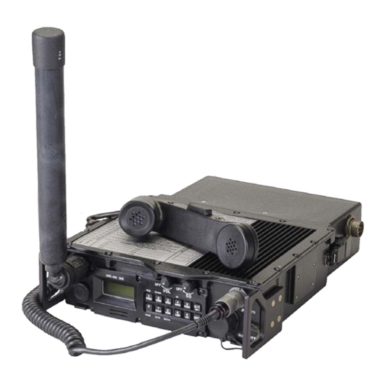
General Dynamics URC-200 (V2) Manuals
Manuals and User Guides for General Dynamics URC-200 (V2). We have
1
General Dynamics URC-200 (V2) manual available for free PDF download: Operation And Maintenance Manual
General Dynamics URC-200 (V2) Operation And Maintenance Manual (153 pages)
LOS TRANSCEIVER
Brand:
General Dynamics
| Category:
Transceiver
| Size: 4.13 MB
Table of Contents
Table of Contents
5
Safety
9
Introduction
11
Purpose and Functions
11
Features
12
Performance Characteristics
12
Table 1 - Performance Characteristics
13
Options
15
Description of the URC-200 (V2) Transceiver
16
Figure 1 - URC-200 (V2) Transceiver Radio
16
Table 2 - Battery Types
17
Table 3 - Equipment Weight and Dimensions
19
Figure 2 - Outline Dimensions
20
Power Requirements
21
Environmental Operation and Storage
21
Table 4 - Environmental Characteristics
21
List of Items Furnished
22
List of Items Not Furnished
22
Table 5 - List of Items Furnished
22
Tools and Test Equipment
25
Shipping and Handling Precautions
25
Preparation for Use and Installation
27
Unpacking
27
Installation
27
Figure 3 - Battery Case
27
Figure 4 - Battery Pack Installation
28
Attaching the Handset
29
Attaching the Antenna
29
Removing the Antenna
30
Transceiver Placement and Antenna Sighting
30
Principles of Operation
31
Transceiver Functional Description
31
Table 6 - URC-200 (V2) Operational Frequency-Based Dependencies
32
Figure 5 - Transceiver Simplified Functional Block Diagram
33
Receiver Functional Description
34
Receiver Input Signals
35
Figure 6 - Receiver Functional Block Diagram
35
Receiver Output Signals
36
Figure 7 - Receiver Output Signal Diagram
36
Transmitter Functional Description
37
Figure 8 - Transmitter Functional Block Diagram
37
Mhz Option Functional Description
38
Figure 9 - 30-90 Mhz Transceiver Simplified Functional Block Diagram
39
Mhz Receiver Functional Description
40
Mhz Transmitter Functional Description
41
Figure 10 - 30-90 Receiver Functional Block Diagram
41
Operating Instructions
43
Transceiver Placement and Antenna Sighting
43
Controls, Indicators and Connectors
43
Figure 11 - Front and Rear Panel Controls, Indicators and Connectors
44
Table 7 - Front Panel Controls, Indicators and Connector and Rear Panel Connectors
44
Keypad and Display Functions
45
Figure 12 - Key-Pad and Display Functions
45
Normal Operating Mode Configuration Procedures
46
Turning on the Unit
46
Cancellation of Presets
47
Front Panel Illumination
47
Select Speaker ON/OFF
47
Select Meter Mode
47
Setting Preset Channels
48
Selecting Special Modes
51
Voice (PT) Operation
54
V2) EEPROM Limitations
54
Select Scan Channels
55
Cancellation of Presets
55
Select Preset Channels
55
Storing Presets
55
Alignment Command Limitations
55
Remote Operation
55
Figure 13 - Remote-Control Unit
55
Remote Control Interconnect
56
Data Rates and Logic Levels
56
Table 8 - Remote Control Interconnect
56
Data Exchange Protocol
57
Figure 14 - Hyperterminal Configuration
57
Remote Control Codes
58
Table 9 - Remote Responses
58
Table 10 - URC-200 (V2) Operational Frequency-Based Dependencies
59
Table 11 - Remote Transceiver Operation Commands
60
Table 12 - Transceiver Customizing Codes
67
Table 13 - Transceiver Status Inquiry Commands
69
Options
74
EBN-30, 30 to 90 Mhz Option
74
Table 14 - 30 to 90 Mhz Specifications
75
Table 15 - LVHF Band Required Equipment
76
EBN-400, 400 to 420 MHZ Option
77
Figure 15 - 30 to 90 Mhz Option Front Panel
77
Table 16 - 400 to 420 Mhz Specifications
78
Table 17 - 400 to 420 Mhz Band Required Equipment
78
ECS-8, 8.33 Khz Option
79
Aviation Mode
80
Table 18 - Aviation Mode Frequency Chart
81
Maintenance
83
Cleaning
83
Performance Verification
83
Manual System Test
83
Test Equipment Required
83
Table 19 - Test Equipment Required
84
Table 20 - Alternate Test Equipment
84
Receiver Tests
85
Figure 16 - Receiver Test Equipment Setup
86
Table 21 - FM Frequency Presets
87
Table 22 - am Frequency Presets
92
Transmitter Tests
108
Figure 17 - Transmitter Test Setup
110
Power Supply Voltages
127
Table 23 - Internal Voltages
127
Inspection
129
Troubleshooting
129
Figure 18 - Breakout Box Schematic
129
Shipping
130
Storage
130
Table 24 - Error Messages
130
Electrical Interfaces
131
Table 25 - Power Connector J1 (CA110821-1) Pin Characteristics
131
Table 26 - Power Connector J5 (CA110821-1) Pin Characteristics
132
Table 27 - Handset Connector J4 (GC283F-1-050) Pin Characteristics
132
Table 28 - Remote Connector J2 (MS3114E16-26S) Pin Characteristics
133
Table 29 - URC-200 (V2) Connector Identification
135
Figure 19 - URC-200 (V2) Interfaces
136
Parts List
137
Table 30 - URC-200 (V2) Parts
137
V2) Systems
139
Rack Mounted Base System
139
Rack Mounted Base System Description of Operation
139
Figure 20 - Rack Mount System Components
139
Figure 21 - Rack Mount System Block Diagram with AC Power Supply
140
Rack Mounted Base System Installation
141
Rack Mounted Base System Operation
142
Rack Mounted Base System Troubleshooting
143
Rack Mounted System Remove and Replace Procedures
143
Figure 22 - Rack Mounted Installed System
144
Figure 23 - Rack Mount Tray Hardware
144
Portable Backpack System
146
Backpack System Description of Operation
147
Figure 24 - Backpack System Components
147
Figure 25 - Backpack System Block Diagram
148
Backpack System Installation
149
Backpack System Operation
149
Appendixa - Urc-200 (V2) Crystal Warp Adjustment
151
Advertisement
Advertisement
Related Products
General Dynamics Categories
Antenna
Laptop
Receiver
Measuring Instruments
Tablet
More General Dynamics Manuals
Login
Sign In
OR
Sign in with Facebook
Sign in with Google
Upload manual
Upload from disk
Upload from URL