Table of Contents
Advertisement
Quick Links
Advertisement
Table of Contents
Troubleshooting

Summary of Contents for General Dynamics URC-200 (V2)
- Page 1 URC-200 (V2) LOS TRANSCEIVER OPERATION AND MAINTENANCE MANUAL 8220 East Roosevelt Street, M/D R3163 Scottsdale, AZ 85257 Contract Number: N65236-09-D-3532 Document No: 99-P42304K File Name: URC200V2_99-P42304K _RevD.doc Revision: D Revision Date: March 2011...
- Page 3 Reg. U.S. P.T.O. All other product or service names are the property of their respective owners. General Dynamics reserves the right to make changes in its products and specifications at any time and without notice. General Dynamics C4 Systems, Inc.
-
Page 5: Table Of Contents
Ge n e ra l Dyn a m ic s C4 S ys te m s URC-200 (V2) TABLE OF CONTENTS SAFETY ............................. v INTRODUCTION ........................1 Purpose and Functions ......................1 Features ..........................2 Performance Characteristics ....................2 1.3.1 Options .......................... - Page 6 Ge n e ra l Dyn a m ic s C4 S ys te m s URC-200 (V2) 4.5.3 Select Preset Channels ....................45 4.5.4 Storing Presets ........................ 45 4.5.5 Alignment Command Limitations .................. 45 Remote Operation ......................45 4.6.1 Remote Control Interconnect..................
- Page 7 Ge n e ra l Dyn a m ic s C4 S ys te m s URC-200 (V2) LIST OF FIGURES Figure 1 - URC-200 (V2) Transceiver Radio ..................6 Figure 2 - Outline Dimensions ......................10 Figure 3 - Battery Case ........................17 Figure 4 - Battery Pack Installation ....................
- Page 8 Ge n e ra l Dyn a m ic s C4 S ys te m s URC-200 (V2) Table 17 - 400 to 420 MHz Band Required Equipment ..............68 Table 18 - Aviation Mode Frequency Chart ..................71 Table 19 - Test Equipment Required ....................74 Table 20 - Alternate Test Equipment ....................
-
Page 9: Safety
Ge n e ra l Dyn a m ic s C4 S ys te m s URC-200 (V2) SAFETY CAUTION To comply with RF exposure requirements, a minimum separation distance of 20 cm (7.9 inches) is required between the antenna and all persons while the transceiver is transmitting. - Page 10 Ge n e ra l Dyn a m ic s C4 S ys te m s URC-200 (V2) CAUTION DO NOT install the LOS antenna on the transceiver during testing in the transmit mode with (1) the cover removed or (2) the transceiver powered from an external power supply via test leads that are unshielded.
-
Page 11: Introduction
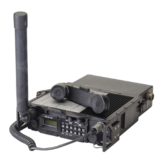
Ge n e ra l Dyn a m ic s C4 S ys te m s URC-200 (V2) 1.0 INTRODUCTION This manual provides operation and maintenance instructions for the URC-200 (V2) Radio Set, part number 01-P36744M003, shown in Figure 1. The radio set is a lightweight VHF/UHF transceiver providing AM/FM transmission and reception of non-secure voice or data in the frequency bands used in maritime, land, mobile and tactical line-of sight communications, as well as military and civilian air traffic control operations. -
Page 12: Features
Ge n e ra l Dyn a m ic s C4 S ys te m s URC-200 (V2) Three options are available. Refer to Paragraph 4.7 for a full description of each option. • A 30-90 MHz FM Low VHF option. •... -
Page 13: Table 1 - Performance Characteristics
Ge n e ra l Dyn a m ic s C4 S ys te m s URC-200 (V2) Table 1 – Performance Characteristics (Continued) ° Standard Test Conditions: 28VDC Input, +25 Characteristics Specifications Estimated Battery Hours, based on 9:1 ratio receive to transmit. Life (2 Batteries) BA-5390/U BA-5590B/U... - Page 14 Ge n e ra l Dyn a m ic s C4 S ys te m s URC-200 (V2) Transmitter Characteristics High Power Tolerance Expressed in Expressed in Expressed Expressed in Output Mode Watts Avg. dBm Avg. in Watts dBm CW Maximum (+2 15.85 Watts 42 dBm...
-
Page 15: Options
Ge n e ra l Dyn a m ic s C4 S ys te m s URC-200 (V2) Transmitter Characteristics (Cont.) Modulation (Cont.) FM (CT) ±5.0 kHz at 1 kHz. ±5.6 kHz at 1 kHz. Spurious >=70 dB below CW carrier (typical) Outputs Harmonic >=53 dB below CW carrier... -
Page 16: Description Of The Urc-200 (V2) Transceiver
Ge n e ra l Dyn a m ic s C4 S ys te m s URC-200 (V2) It also allows the operator to place the radio into Aviation Mode, which restricts the operating frequency range from 117.9750 to 136.9750 MHz, with tuning increments of 25 and 8.33 kHz. A channel spacing of 25 or 8.33 kHz (receive only) is assigned automatically by channel entry. -
Page 17: Table 2 - Battery Types
Ge n e ra l Dyn a m ic s C4 S ys te m s URC-200 (V2) 1.3.2.1 Transceiver - URC-200 (V2) The transceiver is contained in cast-aluminum housing with all operating controls and connectors located on the front panel. The battery connectors, for two batteries, are located on the rear panel. The front panel components are protected by handles on the sides, and an extension on the top cover protects the volume and squelch controls. - Page 18 Ge n e ra l Dyn a m ic s C4 S ys te m s URC-200 (V2) WARNING DO NOT THROW BATTERIES IN THE TRASH Dispose of all used batteries in accordance with all manufacturer, Federal, State and local laws and regulations. Improper handling, reverse-current operation or high environmental temperatures may cause internally generated heat, fire, or toxic materials and gasses to be released from the battery.
-
Page 19: Table 3 - Equipment Weight And Dimensions
Ge n e ra l Dyn a m ic s C4 S ys te m s URC-200 (V2) Table 3 - Equipment Weight and Dimensions Characteristics Specification Transceiver Height 3.13 inches Width 10.8 inches Depth 9.75 inches (including handles) Weight (approximate) 9.2 pounds (10.4 pounds with 30-90 MHz option) Battery Case Height... -
Page 20: Figure 2 - Outline Dimensions
Ge n e ra l Dyn a m ic s C4 S ys te m s URC-200 (V2) Figure 2 - Outline Dimensions... -
Page 21: Power Requirements
Ge n e ra l Dyn a m ic s C4 S ys te m s URC-200 (V2) 1.4 Power Requirements The power required to operate the URC-200 (V2) is +28 VDC nominal applied to the DC Input port J1, with the following characteristics: •... -
Page 22: List Of Items Furnished
URC-200 (V2) transceiver. Unless otherwise noted, they may be selected and purchased as required from General Dynamics C4 Systems. Other accessories are also available. Please contact General Dynamics C4 Systems or refer to our website at http://www.gdc4s.com... - Page 23 Ge n e ra l Dyn a m ic s C4 S ys te m s URC-200 (V2) Battery Chargers • UBS-110 Battery Charger The UBS-110 is a commercial grade battery charger. It charges one or two BB-390/U or BB-590/U batteries. •...
- Page 24 Ge n e ra l Dyn a m ic s C4 S ys te m s URC-200 (V2) Cables In addition to the cables shown below, other cables for data and audio connections, remote control, power, and RF/Antenna connections are available. Contact General Dynamics Customer Service for more information. • LSCA-103A and LSCA-110 Cable Assemblies The LSCA-103A and LSCA-110 are used to connect to the remote PTSH- 104 Amplified Speaker assembly.
-
Page 25: Tools And Test Equipment
Ge n e ra l Dyn a m ic s C4 S ys te m s URC-200 (V2) • UVU-130 VHF/UHF dual band high gain rugged whip antenna for base station applications. Antenna covers 115MHz - 420 MHz. • UVU-200 VHF/UHF Antenna for base station applications. Antenna covers 115-420Mz. -
Page 27: Preparation For Use And Installation
Ge n e ra l Dyn a m ic s C4 S ys te m s URC-200 (V2) 2.0 PREPARATION FOR USE AND INSTALLATION This section provides instructions and procedures for unpacking, inspection, assembly and installation of the URC-200 (V2). 2.1 Unpacking To unpack, open the outer shipping container and remove the packing material. -
Page 28: Figure 4 - Battery Pack Installation
Ge n e ra l Dyn a m ic s C4 S ys te m s URC-200 (V2) Install the UBC-100 to the rear of the Transceiver: Ensure the transceiver is turned off by turning VOL/OFF control to OFF. Set transceiver face down on the front panel handles as shown in Figure 4. Latch Latch Figure 4 - Battery Pack Installation... -
Page 29: Attaching The Handset
Ge n e ra l Dyn a m ic s C4 S ys te m s URC-200 (V2) WARNING DO NOT THROW BATTERIES IN THE TRASH Dispose of all used batteries in accordance with all manufacturer, Federal, State and local laws and regulations. Improper handling, reverse-current operation or high environmental temperatures may cause internally generated heat, fire, or toxic materials and gasses to be released from the battery. -
Page 30: Removing The Antenna
Ge n e ra l Dyn a m ic s C4 S ys te m s URC-200 (V2) With the ball and swivel joint free to swivel, screw the antenna to the ANT connector using only the collar ring. Exercise extreme care to prevent the threads on the collar ring from cross-threading with the threads on the ANT connector. -
Page 31: Principles Of Operation
Ge n e ra l Dyn a m ic s C4 S ys te m s URC-200 (V2) 3.0 PRINCIPLES OF OPERATION 3.1 Transceiver Functional Description The URC-200 Transceiver operates in VHF and UHF frequency bands in either AM or FM modes. Standard VHF band of frequencies in AM mode is 115 to 149.9950 MHz. -
Page 32: Table 6 - Urc-200 (V2) Operational Frequency-Based Dependencies
Ge n e ra l Dyn a m ic s C4 S ys te m s URC-200 (V2) Table 6 - URC-200 (V2) Operational Frequency-Based Dependencies 30-90 MHz 115 - 173.995 MHz 225 - 399.995 MHz 400-420 MHz PT only Tone Squelch (unless custom (150 Hz) -
Page 33: Figure 5 - Transceiver Simplified Functional Block Diagram
Ge n e ra l Dyn a m ic s C4 S ys te m s URC-200 (V2) Figure 5 - Transceiver Simplified Functional Block Diagram In the receive mode, the RF signal arrives at the antenna and passes through the coupler/detector which is used only in the transmit mode. -
Page 34: Receiver Functional Description
Ge n e ra l Dyn a m ic s C4 S ys te m s URC-200 (V2) be controlled within 2 dB of nominal settings. The coupler/detector also senses reverse power to detect a high VSWR condition. When a high VSWR is detected, the coupler/detector provides a control voltage to the ALC that reduces the output power so that the RF amplifier is not damaged. -
Page 35: Receiver Input Signals
Ge n e ra l Dyn a m ic s C4 S ys te m s URC-200 (V2) amplified and routed to the remote connector on the front panel. For PT operation, the audio signal is amplified and routed to the remote connector, the speaker, and the handset. Figure 6 - Receiver Functional Block Diagram Volume and Squelch control signals are provided by the processor to control the volume and squelch settings of the audio circuitry. -
Page 36: Receiver Output Signals
Ge n e ra l Dyn a m ic s C4 S ys te m s URC-200 (V2) band is inverted.) The LO is used to mix with the RF signal to produce a 45.0 MHz IF signal. A second LO at 55.7 MHz is mixed with 45.0 MHz IF to produce a 10.7 MHz IF within the receiver. The processor provides data and clock signals that are used to set the volume controls. -
Page 37: Transmitter Functional Description
Ge n e ra l Dyn a m ic s C4 S ys te m s URC-200 (V2) 3.3 Transmitter Functional Description Figure 8 shows the functional block diagram for the transmitter. In the transmit mode, the synthesizer generates the transmit signal at the operating frequency in response to frequency data supplied by the processor. -
Page 38: Mhz Option Functional Description
Ge n e ra l Dyn a m ic s C4 S ys te m s URC-200 (V2) The transmitter may be modulated with either AM or FM modulation using either Plain Text (audio) or Cipher Text (data) signals. Both the Plain Text and Cipher Text signals are processed through the same filtering and amplification circuitry used to process the baseband signals in the receive mode. -
Page 39: Figure 9 - 30-90 Mhz Transceiver Simplified Functional Block Diagram
Ge n e ra l Dyn a m ic s C4 S ys te m s URC-200 (V2) Figure 9 - 30-90 MHz Transceiver Simplified Functional Block Diagram In receive mode, the RF signal arrives at the 30-90 antenna port and is passed through a coupler/detector which is used only in transmit mode. -
Page 40: Mhz Receiver Functional Description
Ge n e ra l Dyn a m ic s C4 S ys te m s URC-200 (V2) All 30-90 functions are controlled by the APPS processor circuitry that accepts inputs either from the front panel keyboard or from a remote control unit connected to the remote connector. The processor uses a control bus to set the 30-90 circuitry for appropriate operating modes, as determined by the selection of power settings and receive or transmit operation. -
Page 41: Mhz Transmitter Functional Description
Ge n e ra l Dyn a m ic s C4 S ys te m s URC-200 (V2) Figure 10 - 30-90 Receiver Functional Block Diagram 3.4.2 30-90 MHz Tra n s m itte r Fu n c tio n a l De s c rip tio n Refer to Figure 8 for the functional block diagram for the transmitter. - Page 42 Ge n e ra l Dyn a m ic s C4 S ys te m s URC-200 (V2) senses both forward and reflected power used by the ALC to determine the amount of attenuation required by the VCA. The transmitter is modulated with FM modulation only, using either Plain Text (audio) or Cipher Text (data) signals.
-
Page 43: Operating Instructions
Ge n e ra l Dyn a m ic s C4 S ys te m s URC-200 (V2) 4.0 OPERATING INSTRUCTIONS This section provides information for operating the URC-200 (V2) Transceiver. It includes a functional description of all operating controls, indicators, and connectors and procedures for set-up and operation. -
Page 44: Figure 11 - Front And Rear Panel Controls, Indicators And Connectors
Ge n e ra l Dyn a m ic s C4 S ys te m s URC-200 (V2) Figure 11 - Front and Rear Panel Controls, Indicators and Connectors Table 7 - Front Panel Controls, Indicators and Connector and Rear Panel Connectors Controls, Item Indicators,... -
Page 45: Keypad And Display Functions
Ge n e ra l Dyn a m ic s C4 S ys te m s URC-200 (V2) Table 7 - Front Panel Controls, Indicators and Connector and Rear Panel Connectors (Continued) Controls, Item Indicators, Type Function Connectors Battery 6-pin battery Connects transceiver to a power source such as the UBC-100 connector connector... -
Page 46: Normal Operating Mode Configuration Procedures
Ge n e ra l Dyn a m ic s C4 S ys te m s URC-200 (V2) 4.4 Normal Operating Mode Configuration Procedures The transceiver can be used for operation once it has been installed. The transceiver is fully micro- processor-controlled from push button instructions selected at the front panel. -
Page 47: Cancellation Of Presets
Ge n e ra l Dyn a m ic s C4 S ys te m s URC-200 (V2) 4.4.2 Cancellation of Presets To cancel presets, press the [Mode] key while powering on the radio. If the transceiver is powered-up while the [MODE] key is pressed, The transceiver will preset all the channel data for each channel to the default values (225 MHz, PT, AM, low power, 25 kHz channel spacing). -
Page 48: Setting Preset Channels
Ge n e ra l Dyn a m ic s C4 S ys te m s URC-200 (V2) 4.4.6 Setting Preset Channels This section describes how the preset channels are set. The transceiver is initially assumed to be set up with the following conditions: low power, AM, plain text (PT), and a frequency of 225 MHz (for both receive and transmit), these are default values that are achieved when the transceiver is powered-up with the [MODE] key pressed, as described in Paragraph 4.4.2, above. - Page 49 The transceiver will not accept invalid frequencies. If a flashing frequency is displayed on the transceiver’s screen, it may be an indication that a malfunction has occurred. Contact General Dynamics Customer Support for further information if this occurs. 4.4.6.3 Select Modulation Mode Pressing the [AM/FM] key causes the transceiver to toggle between the AM and FM modulation modes for the currently displayed channel.
- Page 50 Ge n e ra l Dyn a m ic s C4 S ys te m s URC-200 (V2) 4.4.6.4 Select Cipher Text/Plain Text Press the [PT/CT] key to toggle between the plain text and cipher text (data) modes for the currently displayed channel. The new value will take effect immediately, as indicated by the annunciator, but will not be saved until the [STO] key is pressed.
-
Page 51: Selecting Special Modes
Ge n e ra l Dyn a m ic s C4 S ys te m s URC-200 (V2) 4.4.6.7 Select Scan Channels Pressing the [SCAN] key switches the selected preset channel on or off the scan list. The scan list must contain from two to ten of the preset channels before the scan mode can operate. - Page 52 Ge n e ra l Dyn a m ic s C4 S ys te m s URC-200 (V2) 4.4.7.1 Select Scan Mode Pressing the [MODE] key and then the [SCAN] key activates or de- activates the SCAN MODE. The scan mode causes the transceiver to cycle through the preset channels which are flagged as "scan channels", (see Paragraph 4.4.6.7), searching for an active channel (i.e., one where incoming signal strength is sufficiently large to break squelch).
- Page 53 Ge n e ra l Dyn a m ic s C4 S ys te m s URC-200 (V2) 4.4.7.2 Select Beacon Mode Pressing the [MODE] key and then the [BCN] key activates or de- activates the BEACON MODE. When the BEACON MODE is selected, the transceiver transmits a sweeping emergency audio signal on the selected channel frequency and in the selected modulation mode (AM or FM).
-
Page 54: Voice (Pt) Operation
Ge n e ra l Dyn a m ic s C4 S ys te m s URC-200 (V2) 4.4.7.4 Release from Remote Control Pressing the [MODE] key and then the [R/T] key returns the transceiver to local control from remote control. This sequence is called Release Remote Key Sequence (RRKS). -
Page 55: Select Scan Channels
This value should rarely require adjustment (typically once a year or less often). For information concerning the warp alignment command, please contact General Dynamics Customer Service. 4.6 Remote Operation The URC-200 (V2) can be operated remotely using one of the available Remote Control Units (UEC-120 or UEC-220) or by using a personal computer. -
Page 56: Remote Control Interconnect
Ge n e ra l Dyn a m ic s C4 S ys te m s URC-200 (V2) When first powered up, the RCU sends an ID interrogation code to query what type of radio it is connected to (what options have been attached). Given this information, the RCU restricts the type of commands that it can transmit to the transceiver. -
Page 57: Data Exchange Protocol
Ge n e ra l Dyn a m ic s C4 S ys te m s URC-200 (V2) Figure 14 - HyperTerminal Configuration The data rate is 1200 bps ±5%. The data code is serial 8-bit ASCII including no parity, one start bit and one stop bit, no flow control. -
Page 58: Remote Control Codes
Ge n e ra l Dyn a m ic s C4 S ys te m s URC-200 (V2) Table 9 - Remote Responses CODE NAME DESCRIPTION Acknowledge Response from the transceiver to a valid RCU command. If the command requires data from the transceiver, the data is sent first, followed by ACK. -
Page 59: Table 10 - Urc-200 (V2) Operational Frequency-Based Dependencies
Ge n e ra l Dyn a m ic s C4 S ys te m s URC-200 (V2) • 8.33 kHz tuning increment / channel spacing option, ECS-8 Many of the commands are only valid for certain transceiver configurations and frequency ranges, Table 10 provides mapping of these dependencies. -
Page 60: Table 11 - Remote Transceiver Operation Commands
Ge n e ra l Dyn a m ic s C4 S ys te m s URC-200 (V2) Table 11 - Remote Transceiver Operation Commands EQUIVALENT TRANSCEIVER CODE NAME DESCRIPTION KEYPAD COMMAND Command sent to the transceiver to None disregard the current remote command (or partial command) and re-sync. - Page 61 Ge n e ra l Dyn a m ic s C4 S ys te m s URC-200 (V2) CAUTION When performing a self calibration, the radio antenna port(s) must be attached directly to a good 50 ohm load(s). BNC type loads are acceptable. Use of a Type N to BNC adapter is recommended on the 30-90MHz antenna port (if present).
- Page 62 Ge n e ra l Dyn a m ic s C4 S ys te m s URC-200 (V2) Table 11 – Remote Transceiver Operation Commands (Continued) EQUIVALENT TRANSCEIVER CODE NAME DESCRIPTION KEYPAD COMMAND Receive The "R" Command sets the receive Note 1 Frequency frequency value for the current preset...
- Page 63 Ge n e ra l Dyn a m ic s C4 S ys te m s URC-200 (V2) Table 11 – Remote Transceiver Operation Commands (Continued) EQUIVALENT TRANSCEIVER CODE NAME DESCRIPTION KEYPAD COMMAND Transmit The “T” Command sets the transmit Note 1 Frequency frequency value for the current preset...
- Page 64 Ge n e ra l Dyn a m ic s C4 S ys te m s URC-200 (V2) Table 11 – Remote Transceiver Operation Commands (Continued) EQUIVALENT TRANSCEIVER CODE NAME DESCRIPTION KEYPAD COMMAND Modulation Mode The “M” Command followed by a 0 or 1 Note 1 TRANSMIT/RECEIVE selects the transmit and receive modulation...
- Page 65 Ge n e ra l Dyn a m ic s C4 S ys te m s URC-200 (V2) Table 11 – Remote Transceiver Operation Commands (Continued) EQUIVALENT TRANSCEIVER CODE NAME DESCRIPTION KEYPAD COMMAND Power Level The “#” Command followed by a 0, 1, or 2 Note 1 Setting selects the transmitter’s output power for...
- Page 66 Ge n e ra l Dyn a m ic s C4 S ys te m s URC-200 (V2) Table 11 – Remote Transceiver Operation Commands (Continued) EQUIVALENT TRANSCEIVER CODE NAME DESCRIPTION KEYPAD COMMAND Transmit The “B” Command sets the transceiver into Command the transmit mode from the receive mode.
-
Page 67: Table 12 - Transceiver Customizing Codes
Ge n e ra l Dyn a m ic s C4 S ys te m s URC-200 (V2) Table 12 - Transceiver Customizing Codes CODE NAME DESCRIPTION The “e” Command followed by the appropriate two decimal digits Transceiver’s sets the state of the transceiver’s internal speaker when transceiver is Internal Speaker turned ON. - Page 68 ONLY VALID for software version 1.6 and later. For previous Wxxxx Warp Command software versions, please call General Dynamics. The “W” command followed by four decimal digits from 0000 to 1023 adjusts the crystal warp value. This is used to fine tune the transceiver frequency accuracy.
-
Page 69: Table 13 - Transceiver Status Inquiry Commands
Ge n e ra l Dyn a m ic s C4 S ys te m s URC-200 (V2) Table 13 - Transceiver Status Inquiry Commands CODE NAME DESCRIPTION Synth The transceiver responds to whether its synthesizer is in a lock or Lock/Unlock unlock condition. - Page 70 Ge n e ra l Dyn a m ic s C4 S ys te m s URC-200 (V2) Table 13 – Transceiver Status Inquire Commands (Continued) CODE NAME DESCRIPTION SW Version The transceiver responds by sending back a value representing the software version followed by the date and time of compilation.
- Page 71 Ge n e ra l Dyn a m ic s C4 S ys te m s URC-200 (V2) Table 13 – Transceiver Status Inquire Commands (Continued) CODE NAME DESCRIPTION General Status Gives the general status of the transceiver in the form : “XxJjLldyFfvzzz”...
- Page 72 Ge n e ra l Dyn a m ic s C4 S ys te m s URC-200 (V2) Table 13 – Transceiver Status Inquire Commands (Continued) CODE NAME DESCRIPTION Power Level Returns value in the form: "&aaabbbcccdddeeefffggghhhiiijjjkkk" Values aaa = AM Low value. bbb = AM High value.
- Page 73 Ge n e ra l Dyn a m ic s C4 S ys te m s URC-200 (V2) Table 13 – Transceiver Status Inquire Commands (Continued) CODE NAME DESCRIPTION Transceiver Value is returned in the form: “q.00a.01b.02c.03d” Control Modes a = 0 if transceiver in old RF card mode. = 1 if transceiver in new RF card mode.
-
Page 74: Options
Ge n e ra l Dyn a m ic s C4 S ys te m s URC-200 (V2) Table 13 – Transceiver Status Inquire Commands (Continued) CODE NAME DESCRIPTION Receiver Filter Returns value in the form: “<xxxx” Bandwidth xxxx = bandwidth value for the current Rx channel (25 KHz or 8.33 Selection KHz) Debug Inquiry... -
Page 75: Table 14 - 30 To 90 Mhz Specifications
Ge n e ra l Dyn a m ic s C4 S ys te m s URC-200 (V2) 4.7.1.5 Select Meter Mode The front panel display signal strength meter and power meter do not operate when the transceiver is in the 30 to 90 MHz band. 4.7.1.6 UEC-120/220 Remote Control Optional Accessory Use only the UEC-120/220 Remote Control Units when operating the URC-200 (V2) with the 30 to 90 MHz Option. -
Page 76: Table 15 - Lvhf Band Required Equipment
Ge n e ra l Dyn a m ic s C4 S ys te m s URC-200 (V2) 4.7.1.8 Required System Equipment Table 15 identifies minimum required equipment for a self-contained LOS communications device operating in the LVHF band. Table 15 - LVHF Band Required Equipment Quantity Required Part Number Nomenclature... -
Page 77: Ebn-400, 400 To 420 Mhz Option
Ge n e ra l Dyn a m ic s C4 S ys te m s URC-200 (V2) If desired, the 150 Hz Tone Squelch may be deactivated, or turned OFF. The lower case “t” will disappear from the 100 MHz position on the display when the Tone Squelch is turned OFF. With the tone turned OFF there is no squelching of the white-noise on the URC-200 (V2). -
Page 78: Table 16 - 400 To 420 Mhz Specifications
Ge n e ra l Dyn a m ic s C4 S ys te m s URC-200 (V2) 4.7.2.4 Specifications Table 16 identifies specifications pertaining only to the 400 to 420 MHz option within a URC-200 (V2) transceiver. Table 16 - 400 to 420 MHz Specifications General 400 to 420 MHz Frequency Range:... -
Page 79: Ecs-8, 8.33 Khz Option
Ge n e ra l Dyn a m ic s C4 S ys te m s URC-200 (V2) 4.7.3 ECS-8, 8.33 kHz Option Part Number 01-P42311K001. The ECS-8 option provides three features: • ECS-8 allows the user to choose a channel spacing of either 25 kHz or 8.33 kHz in the frequency range of 117.9750 to 136.9750 MHz when in AM PT mode. -
Page 80: Aviation Mode
Ge n e ra l Dyn a m ic s C4 S ys te m s URC-200 (V2) Avia tio n m o d e To place the transceiver in the Aviation Mode, start with the transceiver powered off and then press and hold the 4 [AV] keypad while turning on the power. -
Page 81: Table 18 - Aviation Mode Frequency Chart
Ge n e ra l Dyn a m ic s C4 S ys te m s URC-200 (V2) In a similar fashion, line 4 of the chart shows that the next available frequency is 118.0166 MHz. This also is only allowed to have a channel spacing of 8.33 kHz. To operate at this setting, enter 118015 to the transceiver. - Page 82 Ge n e ra l Dyn a m ic s C4 S ys te m s URC-200 (V2) In the URC-200 (V2) with the ECS-8 option installed (8.33kHz tuning), the channel spacing (IF selectivity) is selectable (8.33kHz or 25kHz) within the 117.975 to 137.975 MHz band in AM PT mode, in accordance with ICAO standards per Annex 10 to the Convention on International Civil Aviation, Volume V.
-
Page 83: Maintenance
5.3 Manual System Test The manual system test checks the operating parameters of the URC-200 (V2) under test, using General Dynamics Analyzer (R2600 series) as the primary test equipment. CAUTION To comply with RF exposure requirements, a minimum separation distance of 20 cm (7.9 inches) is required between the antenna and all persons while the... -
Page 84: Table 19 - Test Equipment Required
Part No. Supplier Power Supply, 28 VDC, 5A HP-6291 A Hewlett-Packard Communications System Analyzer R2600 General Dynamics Breakout Box For REMOTE Connector Current Meter HP-428B Hewlett-Packard NOTE • Verify the test equipment has been calibrated. • When verifying the various test measurements against the operating parameters as listed in Table 1, take into consideration the accuracy of the test equipment being used. -
Page 85: Receiver Tests
AM and FM, and in CT and PT modes. Squelch sensitivity will also be checked. If the transceiver fails any of the tests, or if it cannot be adjusted to the specified values, it must be sent to General Dynamics C4 Systems for repair. -
Page 86: Figure 16 - Receiver Test Equipment Setup
Ge n e ra l Dyn a m ic s C4 S ys te m s URC-200 (V2) Figure 16 - Receiver Test Equipment Setup 3. Preset the R2600 by performing the following steps. a. Press the MEM (Memory) key on the R2600 panel for the preset-screen. b. -
Page 87: Table 21 - Fm Frequency Presets
Ge n e ra l Dyn a m ic s C4 S ys te m s URC-200 (V2) i. Move the cursor to the Duplex Offset position and press the "DON'T CARE" soft key. j. Move the cursor to Synth. Format Sel (Synthesizer Format Select) and select the "Tone A"... - Page 88 Ge n e ra l Dyn a m ic s C4 S ys te m s URC-200 (V2) i. Move the cursor to the Display position and depress the "EXT SCOPE" soft key. j. Move the cursor to the Coupling position and depress the "AC" soft key. k.
- Page 89 Ge n e ra l Dyn a m ic s C4 S ys te m s URC-200 (V2) FM PT Distortion is displayed in percent in the Display area of the CRT screen. Verify compliance with Table 1. g. On both the URC-200 (V2) and the R2600 repeat steps A through F for preselect channels 2 through 9 and channel 0 on the URC-200 (V2) with the R2600 set on preset channel 10.
- Page 90 Ge n e ra l Dyn a m ic s C4 S ys te m s URC-200 (V2) a. Press RF key on the R2600 panel. Move the cursor to RF Control and press the "GEN" soft key. b. Move the cursor to the Output Lvl (RF Output Level) position and enter a level of -050.0 dBm from the keypad.
- Page 91 Ge n e ra l Dyn a m ic s C4 S ys te m s URC-200 (V2) p. Adjust both the SQUELCH and VOLUME controls on the front panel to their maximum CCW positions. 5. Setup the URC-200 (V2) as follows: a.
-
Page 92: Table 22 - Am Frequency Presets
Ge n e ra l Dyn a m ic s C4 S ys te m s URC-200 (V2) e. Move the cursor to Modulation Type and press the "AM" soft key. f. Move the cursor to the Generate Frequency position and enter 115.000 from the R2600 keypad. - Page 93 Ge n e ra l Dyn a m ic s C4 S ys te m s URC-200 (V2) NOTE This is AM Modulation. Depress the RIGHT ARROW CURSOR CONTROL key and depress “Cont” (Continuous) soft key. e. Move the cursor to the Fixed 1 kHz position. Depress the LEFT ARROW CURSOR CONTROL key and then depress the "Off"...
- Page 94 Ge n e ra l Dyn a m ic s C4 S ys te m s URC-200 (V2) b. Set the frequency presets as listed in Table 22 on the URC-200 (V2). For each preset channel, adjust the URC-200 (V2) for the following: AM, PT, SCN OFF, BCN OFF To configure presets, refer to Paragraph 4.4.6.
- Page 95 Ge n e ra l Dyn a m ic s C4 S ys te m s URC-200 (V2) d. Use the CURSOR POSITION keys to the Monitor Frequency position and enter 115.000 from the R2600 keypad. e. Move the cursor to Modulation Type and press the "AM" soft key. f.
- Page 96 Ge n e ra l Dyn a m ic s C4 S ys te m s URC-200 (V2) NOTE The “more” soft key may have to be depressed for the “AC VOLTS” soft key to be displayed. h. Move the cursor to the Range position and depress the "AUTO" soft key. i.
- Page 97 Ge n e ra l Dyn a m ic s C4 S ys te m s URC-200 (V2) c. Verify the 8kHz waveform pattern on the screen of the R2600 has an amplitude of 4 VPP to 24 VPP. Verify the square wave pattern is the same as it was with a -50dBm signal except for the slight jumping around of the 8kHz pattern.
- Page 98 Ge n e ra l Dyn a m ic s C4 S ys te m s URC-200 (V2) a. Press RF key on the R2600 panel. Move the cursor to RF Control and press the "GEN" soft key. b. Move the cursor to the Output Lvl (RF Output Level) position and enter a level of -080.0 dBm from the keypad.
- Page 99 Ge n e ra l Dyn a m ic s C4 S ys te m s URC-200 (V2) p. Adjust both the SQUELCH and VOLUME controls on the front panel to their maximum CCW positions. 5. Setup the URC-200 (V2) as follows: a.
- Page 100 Ge n e ra l Dyn a m ic s C4 S ys te m s URC-200 (V2) 3. Preset the R2600 by performing the following steps. a. Press the MEM (Memory) key on the R2600 panel for the preset-screen. b.
- Page 101 Ge n e ra l Dyn a m ic s C4 S ys te m s URC-200 (V2) f. Verify the DTMF position and the External position are both OFF. g. Depress the DISP (Display) key on the R2600 panel. Move the cursor to the Meter position and depress the "AC VOLTS"...
- Page 102 Ge n e ra l Dyn a m ic s C4 S ys te m s URC-200 (V2) NOTE The “more” soft key may have to be depressed for the “500 us” soft key to be displayed. n. Move the cursor to the Vert (Vertical) position and depress the "1 V" soft key. NOTE The “more”...
- Page 103 Ge n e ra l Dyn a m ic s C4 S ys te m s URC-200 (V2) 3. Preset the R2600 by performing the following steps. a. Press the MEM (Memory) key on the R2600 panel for the preset-screen. b.
- Page 104 Ge n e ra l Dyn a m ic s C4 S ys te m s URC-200 (V2) e. Move the cursor to the Fixed 1 kHz position. Depress the LEFT ARROW CURSOR CONTROL key and then depress the "Off" soft key. f.
- Page 105 Ge n e ra l Dyn a m ic s C4 S ys te m s URC-200 (V2) Adjust the SQ (Squelch) control fully counter-clockwise, past its detent, to the OFF position. 6. Scan Function Measurements: a. On the R2600 front panel depress the RF key. Move the cursor to the Output Lvl (RF Output Level) position.
- Page 106 Ge n e ra l Dyn a m ic s C4 S ys te m s URC-200 (V2) e. Move the cursor to Modulation Type and press the "FM" soft key. f. Move the cursor to the Generate Frequency position and enter 173.975 from the R2600 keypad.
- Page 107 Ge n e ra l Dyn a m ic s C4 S ys te m s URC-200 (V2) k. Move the cursor to the Trigger position and depress the "AUTO" soft key. l. Move the cursor to the Trigger Lvl (Trigger Level) position and enter 500 from the keypad.
-
Page 108: Transmitter Tests
Ge n e ra l Dyn a m ic s C4 S ys te m s URC-200 (V2) 5.3.3 Transmitter Tests The following tests evaluate the performance of the XMT circuits. Tests include frequency accuracy, output power, PT/CT modulation, modulation distortion, and beacon. If the transceiver fails any of the tests, or if it cannot be adjusted to specified values, it must be sent to General Dynamics C4 Systems for repair. - Page 109 This procedure only applies to transceivers with software version 1.6 and later. For radios with older software please contact General Dynamics Customer Support. Set up the test equipment as shown in Figure 17. Connect the VERT/SINAD/DIST/DVM/COUNTER IN connector to the DEMOD connector on the R2600.
-
Page 110: Figure 17 - Transmitter Test Setup
Ge n e ra l Dyn a m ic s C4 S ys te m s URC-200 (V2) Figure 17 - Transmitter Test Setup Preset the R2600 by performing the following steps. a. Press the MEM (Memory) key on the R2600 panel for the preset-screen. b. - Page 111 Ge n e ra l Dyn a m ic s C4 S ys te m s URC-200 (V2) i. Move the cursor to the Duplex Offset position and press the "DON'T CARE" soft key. j. Move the cursor to Synth. Format Sel (Synthesizer Format Select) and select the "Tone A"...
- Page 112 Ge n e ra l Dyn a m ic s C4 S ys te m s URC-200 (V2) NOTE The “more” soft key may have to be depressed for the “500 us” soft key to be displayed. n. Move the cursor to the Vert (Vertical) position and depress the "200 mV" soft key. NOTE The “more”...
- Page 113 Ge n e ra l Dyn a m ic s C4 S ys te m s URC-200 (V2) Connect the VERT/SINAD/DIST/DVM/COUNTER IN connector to the DEMOD connector on the R2600. On the R2600 connect the MOD OUT connector to pins H and J of the REMOTE connector on the URC-200 (V2).
- Page 114 Ge n e ra l Dyn a m ic s C4 S ys te m s URC-200 (V2) b. Move the cursor to the Attenuation position and press the "40" soft key. c. Move the cursor to the Mon RF Out position and press the "RF IN/OUT" soft key. d.
- Page 115 Ge n e ra l Dyn a m ic s C4 S ys te m s URC-200 (V2) a. Turn the transceiver on and note the input current. It should be approximately 240mA. If the current exceeds 330mA, a problem exists in the transceiver. Turn off the power and troubleshoot the transceiver.
- Page 116 Ge n e ra l Dyn a m ic s C4 S ys te m s URC-200 (V2) 5.3.3.3 FM CT Deviation and Distortion 1. Set up the test equipment as shown in Figure 17. Connect the VERT/SINAD/DIST/DVM/COUNTER IN connector to the DEMOD connector on the R2600.
- Page 117 Ge n e ra l Dyn a m ic s C4 S ys te m s URC-200 (V2) 4. Perform the following steps to complete the setup on the R2600 analyzer. a. Press RF key on the R2600 panel. Move the cursor to RF Control and press the "MON" soft key.
- Page 118 Ge n e ra l Dyn a m ic s C4 S ys te m s URC-200 (V2) 5. Setup the URC-200 (V2) as follows: a. Turn the transceiver on and note the input current. It should be approximately 240mA. If the current exceeds 330mA, a problem exists in the transceiver.
- Page 119 Ge n e ra l Dyn a m ic s C4 S ys te m s URC-200 (V2) d. Using the CURSOR POSITION keys move to the Monitor Frequency position and enter 115.000 from the R2600 keypad. e. Move the cursor to Modulation Type and press the "AM" soft key. f.
- Page 120 Ge n e ra l Dyn a m ic s C4 S ys te m s URC-200 (V2) h. Move the cursor to the Input Lvl Input Level) position and depress the "dBm" soft key. i. Move the cursor to the Display position and depress the "EXT SCOPE" soft key. j.
- Page 121 Ge n e ra l Dyn a m ic s C4 S ys te m s URC-200 (V2) NOTE When measuring AM transmitter output power on the R2600 or on any power meter that has a peak detector, which includes virtually all of the portable inline or direct power meters, the carrier power that is read on the wattmeter will need to be converted to average power to verify compliance as indicated above.
- Page 122 Ge n e ra l Dyn a m ic s C4 S ys te m s URC-200 (V2) h. On both the URC-200 (V2) and the R2600 repeat steps A through E for preselect channels 2 through 9 and channel 0 on the URC-200 (V2) with the R2600 set on preset channel 10.
- Page 123 Ge n e ra l Dyn a m ic s C4 S ys te m s URC-200 (V2) m. Press the "return" soft key. Repeat steps A through K for presets 02 through 10. Use Table 22 to program the frequency presets in steps D and E above. n.
- Page 124 Ge n e ra l Dyn a m ic s C4 S ys te m s URC-200 (V2) o. Move the cursor to the Pos (Position) position and depress the "move up" or "move down" soft keys as appropriate to center the displayed scope screen trace. The TUNING knob on the R2600 panel may be used in lieu of the "move up"...
- Page 125 Ge n e ra l Dyn a m ic s C4 S ys te m s URC-200 (V2) NOTE The soft keys are the eight keys under the CRT screen on the R2600. d. Using the CURSOR POSITION keys move to the Monitor Frequency position and enter 312.000 from the R2600 keypad.
- Page 126 Ge n e ra l Dyn a m ic s C4 S ys te m s URC-200 (V2) NOTE The “more” soft key may have to be depressed for the “RF DISPLAY” soft key to be displayed. h. Move the cursor to the Input Lvl Input Level) position and depress the "dBm" soft key. i.
-
Page 127: Power Supply Voltages
Six internal voltages can be displayed on the front panel (Table 23). The following table shows the tolerance range for each. If the input voltage is within the specified range and any of the internal voltages are out of tolerance, the transceiver should be returned to General Dynamics for repair. Table 23 - Internal Voltages... - Page 128 Ge n e ra l Dyn a m ic s C4 S ys te m s URC-200 (V2) 5.3.4.3 Voltage Measurements With the transceiver set-up in the meter-mode per Paragraph 4.4.5, pressing the [R/T] key will display the voltages of the internal power supplies and of the batteries.
-
Page 129: Inspection
Ge n e ra l Dyn a m ic s C4 S ys te m s URC-200 (V2) Figure 18 - Breakout Box Schematic When performing the Receiver Tests in accordance with Paragraph 5.3.2 and Figure 16: ● For the PT OUT on pin E of the Breakout Box, Pin D is the ground return. ●... -
Page 130: Shipping
Ge n e ra l Dyn a m ic s C4 S ys te m s URC-200 (V2) Table 24 - Error Messages Display Error Title Description Err – bEAC Beacon Lock Failure This message indicates that there is no synthesizer lock on beacon. -
Page 131: Electrical Interfaces
Ge n e ra l Dyn a m ic s C4 S ys te m s URC-200 (V2) display. The display is rated for storage * Storage temperature does not include the front panel at -40°C to +70°C. 5.8 Electrical Interfaces Figure 11 shows interface connector locations for the URC-200 (V2). -
Page 132: Table 26 - Power Connector J5 (Ca110821-1) Pin Characteristics
Ge n e ra l Dyn a m ic s C4 S ys te m s URC-200 (V2) Table 26 - Power Connector J5 (CA110821-1) Pin Characteristics FUNCTION 12V Battery 1 - Negative / Transceiver Ground for External Power Source 12V Battery 2 - Negative (Tied to Pin 4 internal to the Transceiver) Rechargeable battery sense. -
Page 133: Table 28 - Remote Connector J2 (Ms3114E16-26S) Pin Characteristics
Ge n e ra l Dyn a m ic s C4 S ys te m s URC-200 (V2) Table 28 - Remote Connector J2 (MS3114E16-26S) Pin Characteristics Signal Label Function Impedance Level TX AUDIO – PLAIN TEXT (VOICE) 150 Ω PT IN Plain Text (Voice) 1-200 mV RMS... - Page 134 Ge n e ra l Dyn a m ic s C4 S ys te m s URC-200 (V2) RS-232 REMOTE 470 Ω RS232 TX Remote Control RS232 Data Output RS232 RCV Remote Control RS232 6.8 kΩ Data Input GND-SIGNAL DC Ground ON/OFF REMOTE ON/OFF Remote Power...
-
Page 135: Table 29 - Urc-200 (V2) Connector Identification
Ge n e ra l Dyn a m ic s C4 S ys te m s URC-200 (V2) Signal Label Function Impedance Level GND-CHASSIS Chassis Ground SPARE GROUNDS GND-CHASSIS Chassis Ground Ground, Audio GND-SIGNAL DC Ground The part numbers indicated in Table 29 are 3 party vendor specific and therefore are subject to change without notice. -
Page 136: Figure 19 - Urc-200 (V2) Interfaces
Ge n e ra l Dyn a m ic s C4 S ys te m s URC-200 (V2) Figure 19 - URC-200 (V2) Interfaces... -
Page 137: Parts List
Ge n e ra l Dyn a m ic s C4 S ys te m s URC-200 (V2) 6.0 PARTS LIST Table 30 identifies the URC-200 (V2) parts. Table 30 - URC-200 (V2) Parts Item Number Part Number Description 01-P36744M003 Transceiver URC-200 (V2) 85-P35988M001 Antenna UVU-100... -
Page 139: V2) Systems
Ge n e ra l Dyn a m ic s C4 S ys te m s URC-200 (V2) 7.0 URC-200 (V2) SYSTEMS As a convenience for operators, this section provides information on two commonly installed systems using the URC-200 (V2). Refer to the individual equipment manuals for more detailed information on each of the system components. -
Page 140: Figure 21 - Rack Mount System Block Diagram With Ac Power Supply
Ge n e ra l Dyn a m ic s C4 S ys te m s URC-200 (V2) Figure 21 - Rack Mount System Block Diagram with AC Power Supply 7.1.1.1 Component Interoperation: Power for the system is provided via an external AC power source in the range of 90 to 254 volts or an external DC power source in the range of +26 to +32 VDC (+28 VDC nominal). -
Page 141: Rack Mounted Base System Installation
Ge n e ra l Dyn a m ic s C4 S ys te m s URC-200 (V2) configures and monitors the desired operating mode from either the front panel or via a remote control unit attached to the remote connector. Two remote control units are available: the UEC-120, which controls one transceiver/amplifier pair, and the UEC-220, which can control up to two transceiver/amplifier pairs. -
Page 142: Rack Mounted Base System Operation
Ge n e ra l Dyn a m ic s C4 S ys te m s URC-200 (V2) 7.1.3 Rack Mounted Base System Operation 7.1.3.1 UAC-350 Operation: 1) Ensure the transceiver and power amplifier ON/OFF switches are set in the OFF position. -
Page 143: Rack Mounted Base System Troubleshooting
Ge n e ra l Dyn a m ic s C4 S ys te m s URC-200 (V2) 7.1.3.4 System Functional Test To test the setup, key the transceiver by pressing the PTT switch on the attached audio interface. Before keying, the BYPASS LED on the power amplifier should be lit. When keyed, the URC-200 will display a “TX”... -
Page 144: Figure 22 - Rack Mounted Installed System
Ge n e ra l Dyn a m ic s C4 S ys te m s URC-200 (V2) Figure 22 – Rack Mounted Installed System Figure 23 - Rack Mount Tray Hardware... - Page 145 Ge n e ra l Dyn a m ic s C4 S ys te m s URC-200 (V2) 7.1.5.1 Removing the URC-200 Transceiver and UIB-100 Interface Box: The following steps outline the procedure for removing the URC-200 Transceiver and UIB-100 Interface Box from the Rack Mount System. It is necessary to remove the interface box with the transceiver, because they cannot be detached while installed.
-
Page 146: Portable Backpack System
Ge n e ra l Dyn a m ic s C4 S ys te m s URC-200 (V2) 3. Unscrew the single cap screw from in front of the power amplifier. 4. Slide the power amplifier out from the tray, to release it from the two rear guide pins. -
Page 147: Backpack System Description Of Operation
Ge n e ra l Dyn a m ic s C4 S ys te m s URC-200 (V2) Figure 24 - Backpack System Components 7.2.1 Backpack System Description of Operation Figure 25 depicts the main components and interfaces of the Backpack System. -
Page 148: Figure 25 - Backpack System Block Diagram
Ge n e ra l Dyn a m ic s C4 S ys te m s URC-200 (V2) Figure 25 - Backpack System Block Diagram The URC-200 (V2) VHF/UHF Transceiver is a lightweight, tactical, Line-Of-Sight (LOS) transceiver that provides AM and FM communication of nonsecure voice or data. The UVU-100 Radio Antenna is a ManPack antenna for backpack configuration, weighing approximately one pound, and supporting frequencies of 115 to 174 MHz in VHF band, and 225 to 400 MHz in UHF Band. -
Page 149: Backpack System Installation
Ge n e ra l Dyn a m ic s C4 S ys te m s URC-200 (V2) 7.2.2 Backpack System Installation Installing the Backpack System involves the following steps: 1. Insert two batteries into the UAD-100A Uninterruptable Power Supply. 2. - Page 150 Ge n e ra l Dyn a m ic s C4 S ys te m s URC-200 (V2) 2) Place the transceiver in the supplied canvas carry bag, if desired. 3) Move to desired location and transmit and receive normally using battery power. 7.2.4 Backpack System Troubleshooting When troubleshooting the Backpack System, ensure the following connections are secure:...
-
Page 151: Appendixa - Urc-200 (V2) Crystal Warp Adjustment
RYSTAL DJUSTMENT Software version 1.6 or later only. For software versions prior to 1.6 please contact General Dynamics Customer Support. Introduction The warp adjustment is used to fine tune the transceiver’s frequency accuracy to within ±1ppm. This equates to ± 400 Hz at 400 MHz. To perform the procedure, the radio must be given the Warp command via the REMOTE connector on the front panel of the radio. - Page 152 In this example V0106 indicates the current software version – 1.6. See also Table 13 for additional information about queries. If your radio has an older version of software installed contact General Dynamics support for information concerning the Warp command.
- Page 153 11. When the transmit frequency is within specifications, cycle power to the transceiver to return the radio to the normal operating mode. 12. Key the transceiver and measure the frequency. If it is within specifications, the procedure is complete. If not, contact General Dynamics technical support.
Need help?
Do you have a question about the URC-200 (V2) and is the answer not in the manual?
Questions and answers