Sign In
Upload
Manuals
Brands
Gamry Instruments Manuals
Laboratory Equipment
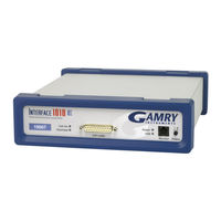
Interface 1010E
Gamry Instruments Interface 1010E Manuals
Manuals and User Guides for Gamry Instruments Interface 1010E. We have
1
Gamry Instruments Interface 1010E manual available for free PDF download: Operator's Manual
Gamry Instruments Interface 1010E Operator's Manual (94 pages)
Potentiostat/Galvanostat/ZRA
Brand:
Gamry Instruments
| Category:
Laboratory Equipment
| Size: 1.54 MB
Table of Contents
If You Have Problems
3
Limited Warranty
3
Copyrights
4
Disclaimers
4
Table of Contents
5
Chapter 1: Safety Considerations
9
Inspection
9
Product Safety
9
AC Mains Connection to the Power Brick
9
Grounding in the Interface 1010
10
Operation with Earth-Grounded Cells and Auxiliary Apparatus
10
Temperature and Ventilation
11
Defects and Abnormal Stresses
11
Environmental Limits
12
Cleaning
12
Service
13
RF Warning
13
Electrical Transient Sensitivity
13
CE Compliance
14
Rohs Compliance
14
Chapter 2: Introduction
15
About this Manual
15
About the Interface 1010
15
Software and Applications
16
Multichannel Systems
16
Front Panel Customization
17
Notational Conventions
17
Chapter 3: Installation
19
Initial Visual Inspection
19
Physical Location
19
Computer Requirements
20
Quick-Start Guide for System Installation
20
Software Installation
20
Reboot Your Computer after Software Installation
20
Power Cord and Power Connection
21
Power up Test
22
USB Cables
22
Multiple Potentiostat Systems
23
Cell Cable Installation
24
Front Panel USB LED
24
Running the Framework
24
Framework Device Status Bar
24
Types of Interface 1010 Instruments
25
Authorization Codes and Label
26
Firmware Update
26
The Interface 1010 Customization Label
26
Introduction to the Interface 1010 Customization Label
26
Label Sheet Provided with each Interface 1010
27
Procedure to Change a Label
27
Chapter 4: Calibration
31
Introduction
31
DC Calibration
31
Cable Calibration
32
Procedure to Calibrate the Cable
33
Chapter 5: Cell Connections
37
Normal Cell Connections
37
ZRA-Mode Cell Connections
38
Membrane Cell Connections
39
Chapter 6: Panel Indicators and Connectors
41
Front Panel
41
Power Switch
41
The Power LED
41
Cell Cable Connector
42
Monitor Connector
42
The USB LED
42
Cell on LED
43
Overload LED
44
Customization Label Area
45
Rear Panel
45
Power in Jack
45
Chassis Ground
46
USB Port
46
User I/O Connector
46
Sync Port
47
Chapter 7: Instrument Circuitry
49
Interface 1010 Schematic/Block Diagrams
49
Chapter 8: Stability in Potentiostat Mode
55
Capacitive Cells and Stability
55
Improving Potentiostat Stability
55
Chapter 9: Measurement of Small Signals
59
Overview
59
Measurement System Model and Physical Limitations
59
Johnson Noise in Z
60
Finite Input Capacitance
61
Leakage Currents and Input Impedance
61
Voltage Noise and DC Measurements
62
Shunt Resistance and Capacitance
62
Hints for System and Cell Design
62
Faraday Shield
62
Avoid External Noise Sources
63
Length and Construction of the Cell Cable
63
Lead Placement
63
Cell Construction
64
Reference Electrode
64
Instrument Settings
64
EIS Speed
64
Ancillary Apparatus
64
Floating Operation
65
Appendix A: Interface 1010 Specifications
67
Control Amplifier
67
Differential Electrometer
68
Voltage Measurement
68
Current to Voltage Converter
69
Current Measurement
69
Potentiostatic Mode
70
Galvanostatic Mode
70
Environmental
70
General
70
Appendix B: Interface 1010 Cell Connector
74
Appendix C: I/O Connectors
76
User I/O Connector
76
Sync Port
77
Monitor Connector
77
I Monitor Signal
78
E Monitor Signal
78
Temperature Monitor Signal
79
External Signal in
79
Appendix D: Power LED Blink Codes
81
Normal Start-Up
81
Failure in an Electronics Module
81
Severe Problem
81
Error Messages and Limitations
81
Error Message this Instrument Is Not Authorized for Freq
81
Error Message this Instrument Is Not Authorized for Ierange
82
Error Message this Instrument Is Not Authorized for Scanrate
82
Error Message this Instrument Is Not Authorized for Sampletime
82
Appendix E: Certifications
83
Declaration of Conformity: No. DOC-2017-CE
83
Declaration of Conformity: No. DOC-2021-UKCA
84
Appendix F: Heat in Interface 1010 Multichannel Systems
85
Introduction to Device Power-Dissipation
85
Potentiostat/Galvanostat Power Model
85
Discharging a Battery
86
Single Interface 1010
87
Vertical Stacks
87
Interface Power Hub Systems
87
Appendix G: Capabilities of Various Models of Interface 1010
89
Appendix H: Index
93
Advertisement
Advertisement
Related Products
Gamry Instruments Interface 1000
Gamry Instruments Interface 1010
Gamry Instruments Interface 1010 19007
Gamry Instruments MultiPort
Gamry Instruments ParaCell
Gamry Instruments PTC1
Gamry Instruments Reference 3000
Gamry Instruments Reference 30k Booster
Gamry Instruments Categories
Laboratory Equipment
Multiplexer
Temperature Controller
Test Equipment
Industrial Equipment
More Gamry Instruments Manuals
Login
Sign In
OR
Sign in with Facebook
Sign in with Google
Upload manual
Upload from disk
Upload from URL